├── .gitignore
├── ContributionPolicy.md
├── Images
├── 96Boards_Sensor_Mezzanine.png
├── Example_Button_LED.png
├── Example_Buzzer_Light.png
├── Example_RGB_LCD.png
├── Example_Temperature_Humidity_LCD.png
├── Example_Touch_Relay.png
├── Example_Tweeting_Doorbell.png
├── Grove_Button_Module.png
├── Grove_Buzzer_Module.jpg
├── Grove_LED_Socket_Module.png
├── Grove_Light_Sensor.png
├── Grove_Mezzanine_Features.png
├── Grove_RGB_Backlight_LCD.jpg
├── Grove_Relay.png
├── Grove_Rotary_Angle_Sensor_Module.png
├── Grove_Servo.jpg
├── Grove_Sound_Sensor.jpg
├── Grove_Temerature_and_Humidity_Sensor.png
├── Grove_Touch_Sensor_Module.png
├── Mounting.jpg
└── README.md
├── LICENSE
├── LegacyGettingStartedGuides
├── 96Boards-Sensorskit-RevC-Getting-Started-A4.pdf
├── 96Boards-Sensorskit-RevC-Getting-Started-A6.pdf
└── 96Boards-Sensorskit-RevC-Getting-Started.odt
├── README.md
├── Sensors.pdf
├── button_led
├── Makefile
└── button_led.ino
├── humid_temp
├── DHT.cpp
├── DHT.h
├── Makefile
├── humid_temp.py
└── read_dht.ino
├── light_buzz
├── Makefile
└── light_buzz.ino
├── rgb_lcd_demo
├── .gitignore
├── Makefile
└── rgb_lcd_demo.cpp
├── touch_switch
├── .gitignore
├── Makefile
└── touch_switch.cpp
└── tweeting_doorbell
├── Makefile
├── tweeting_doorbell.ino
└── tweeting_doorbell.py
/.gitignore:
--------------------------------------------------------------------------------
1 | *.pyc
2 | build-uno/
3 |
--------------------------------------------------------------------------------
/ContributionPolicy.md:
--------------------------------------------------------------------------------
1 | In Progress
2 |
--------------------------------------------------------------------------------
/Images/96Boards_Sensor_Mezzanine.png:
--------------------------------------------------------------------------------
https://raw.githubusercontent.com/96boards/Sensor_Mezzanine_Getting_Started/6456fdf28c66bb3ab10ed3d4c5ae3d2a0c97952f/Images/96Boards_Sensor_Mezzanine.png
--------------------------------------------------------------------------------
/Images/Example_Button_LED.png:
--------------------------------------------------------------------------------
https://raw.githubusercontent.com/96boards/Sensor_Mezzanine_Getting_Started/6456fdf28c66bb3ab10ed3d4c5ae3d2a0c97952f/Images/Example_Button_LED.png
--------------------------------------------------------------------------------
/Images/Example_Buzzer_Light.png:
--------------------------------------------------------------------------------
https://raw.githubusercontent.com/96boards/Sensor_Mezzanine_Getting_Started/6456fdf28c66bb3ab10ed3d4c5ae3d2a0c97952f/Images/Example_Buzzer_Light.png
--------------------------------------------------------------------------------
/Images/Example_RGB_LCD.png:
--------------------------------------------------------------------------------
https://raw.githubusercontent.com/96boards/Sensor_Mezzanine_Getting_Started/6456fdf28c66bb3ab10ed3d4c5ae3d2a0c97952f/Images/Example_RGB_LCD.png
--------------------------------------------------------------------------------
/Images/Example_Temperature_Humidity_LCD.png:
--------------------------------------------------------------------------------
https://raw.githubusercontent.com/96boards/Sensor_Mezzanine_Getting_Started/6456fdf28c66bb3ab10ed3d4c5ae3d2a0c97952f/Images/Example_Temperature_Humidity_LCD.png
--------------------------------------------------------------------------------
/Images/Example_Touch_Relay.png:
--------------------------------------------------------------------------------
https://raw.githubusercontent.com/96boards/Sensor_Mezzanine_Getting_Started/6456fdf28c66bb3ab10ed3d4c5ae3d2a0c97952f/Images/Example_Touch_Relay.png
--------------------------------------------------------------------------------
/Images/Example_Tweeting_Doorbell.png:
--------------------------------------------------------------------------------
https://raw.githubusercontent.com/96boards/Sensor_Mezzanine_Getting_Started/6456fdf28c66bb3ab10ed3d4c5ae3d2a0c97952f/Images/Example_Tweeting_Doorbell.png
--------------------------------------------------------------------------------
/Images/Grove_Button_Module.png:
--------------------------------------------------------------------------------
https://raw.githubusercontent.com/96boards/Sensor_Mezzanine_Getting_Started/6456fdf28c66bb3ab10ed3d4c5ae3d2a0c97952f/Images/Grove_Button_Module.png
--------------------------------------------------------------------------------
/Images/Grove_Buzzer_Module.jpg:
--------------------------------------------------------------------------------
https://raw.githubusercontent.com/96boards/Sensor_Mezzanine_Getting_Started/6456fdf28c66bb3ab10ed3d4c5ae3d2a0c97952f/Images/Grove_Buzzer_Module.jpg
--------------------------------------------------------------------------------
/Images/Grove_LED_Socket_Module.png:
--------------------------------------------------------------------------------
https://raw.githubusercontent.com/96boards/Sensor_Mezzanine_Getting_Started/6456fdf28c66bb3ab10ed3d4c5ae3d2a0c97952f/Images/Grove_LED_Socket_Module.png
--------------------------------------------------------------------------------
/Images/Grove_Light_Sensor.png:
--------------------------------------------------------------------------------
https://raw.githubusercontent.com/96boards/Sensor_Mezzanine_Getting_Started/6456fdf28c66bb3ab10ed3d4c5ae3d2a0c97952f/Images/Grove_Light_Sensor.png
--------------------------------------------------------------------------------
/Images/Grove_Mezzanine_Features.png:
--------------------------------------------------------------------------------
https://raw.githubusercontent.com/96boards/Sensor_Mezzanine_Getting_Started/6456fdf28c66bb3ab10ed3d4c5ae3d2a0c97952f/Images/Grove_Mezzanine_Features.png
--------------------------------------------------------------------------------
/Images/Grove_RGB_Backlight_LCD.jpg:
--------------------------------------------------------------------------------
https://raw.githubusercontent.com/96boards/Sensor_Mezzanine_Getting_Started/6456fdf28c66bb3ab10ed3d4c5ae3d2a0c97952f/Images/Grove_RGB_Backlight_LCD.jpg
--------------------------------------------------------------------------------
/Images/Grove_Relay.png:
--------------------------------------------------------------------------------
https://raw.githubusercontent.com/96boards/Sensor_Mezzanine_Getting_Started/6456fdf28c66bb3ab10ed3d4c5ae3d2a0c97952f/Images/Grove_Relay.png
--------------------------------------------------------------------------------
/Images/Grove_Rotary_Angle_Sensor_Module.png:
--------------------------------------------------------------------------------
https://raw.githubusercontent.com/96boards/Sensor_Mezzanine_Getting_Started/6456fdf28c66bb3ab10ed3d4c5ae3d2a0c97952f/Images/Grove_Rotary_Angle_Sensor_Module.png
--------------------------------------------------------------------------------
/Images/Grove_Servo.jpg:
--------------------------------------------------------------------------------
https://raw.githubusercontent.com/96boards/Sensor_Mezzanine_Getting_Started/6456fdf28c66bb3ab10ed3d4c5ae3d2a0c97952f/Images/Grove_Servo.jpg
--------------------------------------------------------------------------------
/Images/Grove_Sound_Sensor.jpg:
--------------------------------------------------------------------------------
https://raw.githubusercontent.com/96boards/Sensor_Mezzanine_Getting_Started/6456fdf28c66bb3ab10ed3d4c5ae3d2a0c97952f/Images/Grove_Sound_Sensor.jpg
--------------------------------------------------------------------------------
/Images/Grove_Temerature_and_Humidity_Sensor.png:
--------------------------------------------------------------------------------
https://raw.githubusercontent.com/96boards/Sensor_Mezzanine_Getting_Started/6456fdf28c66bb3ab10ed3d4c5ae3d2a0c97952f/Images/Grove_Temerature_and_Humidity_Sensor.png
--------------------------------------------------------------------------------
/Images/Grove_Touch_Sensor_Module.png:
--------------------------------------------------------------------------------
https://raw.githubusercontent.com/96boards/Sensor_Mezzanine_Getting_Started/6456fdf28c66bb3ab10ed3d4c5ae3d2a0c97952f/Images/Grove_Touch_Sensor_Module.png
--------------------------------------------------------------------------------
/Images/Mounting.jpg:
--------------------------------------------------------------------------------
https://raw.githubusercontent.com/96boards/Sensor_Mezzanine_Getting_Started/6456fdf28c66bb3ab10ed3d4c5ae3d2a0c97952f/Images/Mounting.jpg
--------------------------------------------------------------------------------
/Images/README.md:
--------------------------------------------------------------------------------
1 |
2 |
--------------------------------------------------------------------------------
/LICENSE:
--------------------------------------------------------------------------------
1 | Copyright (c) 2015, Linaro, Ltd.
2 | All rights reserved.
3 |
4 | Redistribution and use in source and binary forms, with or without
5 | modification, are permitted provided that the following conditions are
6 | met:
7 |
8 | 1. Redistributions of source code must retain the above copyright
9 | notice, this list of conditions and the following disclaimer.
10 |
11 | 2. Redistributions in binary form must reproduce the above copyright
12 | notice, this list of conditions and the following disclaimer in the
13 | documentation and/or other materials provided with the distribution.
14 |
15 | THIS SOFTWARE IS PROVIDED BY THE COPYRIGHT HOLDERS AND CONTRIBUTORS "AS
16 | IS" AND ANY EXPRESS OR IMPLIED WARRANTIES, INCLUDING, BUT NOT LIMITED
17 | TO, THE IMPLIED WARRANTIES OF MERCHANTABILITY AND FITNESS FOR A
18 | PARTICULAR PURPOSE ARE DISCLAIMED. IN NO EVENT SHALL THE COPYRIGHT
19 | HOLDER OR CONTRIBUTORS BE LIABLE FOR ANY DIRECT, INDIRECT, INCIDENTAL,
20 | SPECIAL, EXEMPLARY, OR CONSEQUENTIAL DAMAGES (INCLUDING, BUT NOT LIMITED
21 | TO, PROCUREMENT OF SUBSTITUTE GOODS OR SERVICES; LOSS OF USE, DATA, OR
22 | PROFITS; OR BUSINESS INTERRUPTION) HOWEVER CAUSED AND ON ANY THEORY OF
23 | LIABILITY, WHETHER IN CONTRACT, STRICT LIABILITY, OR TORT (INCLUDING
24 | NEGLIGENCE OR OTHERWISE) ARISING IN ANY WAY OUT OF THE USE OF THIS
25 | SOFTWARE, EVEN IF ADVISED OF THE POSSIBILITY OF SUCH DAMAGE.
26 |
--------------------------------------------------------------------------------
/LegacyGettingStartedGuides/96Boards-Sensorskit-RevC-Getting-Started-A4.pdf:
--------------------------------------------------------------------------------
https://raw.githubusercontent.com/96boards/Sensor_Mezzanine_Getting_Started/6456fdf28c66bb3ab10ed3d4c5ae3d2a0c97952f/LegacyGettingStartedGuides/96Boards-Sensorskit-RevC-Getting-Started-A4.pdf
--------------------------------------------------------------------------------
/LegacyGettingStartedGuides/96Boards-Sensorskit-RevC-Getting-Started-A6.pdf:
--------------------------------------------------------------------------------
https://raw.githubusercontent.com/96boards/Sensor_Mezzanine_Getting_Started/6456fdf28c66bb3ab10ed3d4c5ae3d2a0c97952f/LegacyGettingStartedGuides/96Boards-Sensorskit-RevC-Getting-Started-A6.pdf
--------------------------------------------------------------------------------
/LegacyGettingStartedGuides/96Boards-Sensorskit-RevC-Getting-Started.odt:
--------------------------------------------------------------------------------
https://raw.githubusercontent.com/96boards/Sensor_Mezzanine_Getting_Started/6456fdf28c66bb3ab10ed3d4c5ae3d2a0c97952f/LegacyGettingStartedGuides/96Boards-Sensorskit-RevC-Getting-Started.odt
--------------------------------------------------------------------------------
/README.md:
--------------------------------------------------------------------------------
1 | # About 96Boards
2 |
3 | 96Boards is the first open specification to define a platform for the delivery of compatible, lowcost,
4 | small footprint, 32-bit and 64-bit Cortex-A boards from a range of ARM SoC vendors.
5 | Standardized expansion buses for peripheral I/O, display and cameras allow the hardware
6 | ecosystem to develop a range of compatible add-on products that will work on any 96Boards
7 | product over the lifetime of the platform.
8 |
9 | http://www.96boards.org
10 |
11 | ***
12 |
13 | # About Grove
14 |
15 | Grove is a system for wiring up sensor and control modules using standardized connectors
16 | and cables. It makes it easy to hook up any of the 100s of available Grove modules to a
17 | microprocessor system without a messy tangle of wires. Each module provides a single
18 | function, such as sensing temperature or driving an LCD.
19 |
20 | http://www.seeed.cc/grove
21 |
22 | ***
23 |
24 | # About the 96Boards Sensors Mezzanine Adapter
25 |
26 | The 96Boards Sensors Mezzanine is an add-on board for any 96Boards compliant baseboard
27 | including the HiKey from either CircuitCo or LeMaker, and the Qualcomm Dragonboard
28 | 410c. The Sensors mezzanine has connections for up to 18 digital, analog and i2c Grove
29 | modules plus an on-board Arduino compatible microcontroller and shield connector.
30 |
31 | https://www.96boards.org/products/mezzanine/sensors-mezzanine/
32 |
33 | ***
34 |
35 | # About Linaro
36 |
37 | Linaro’s mission is to bring together industry and the open source community to work on
38 | key projects, deliver great tools, reduce industry wide fragmentation and redundant effort,
39 | and provide common software foundations for all.
40 |
41 | http://www.linaro.org
42 |
43 | Updates may be made to this guide over time. You can download the most recent version of
44 | this document from the sample code repository on GitHub:
45 | https://github.com/96boards/Starter_Kit_for_96Boards
46 |
47 | Copyright (c) 2016 by Linaro, Ltd. This document is released under a Creative Commons
48 | Attribution-ShareAlike 4.0 International License.
49 |
50 | ***
51 |
52 | # Table of Contents
53 |
54 | - [Included in this Kit](#included-in-this-kit)
55 | - [Introduction to the 96Boards Sensors Mezzanine](#introduction-to-the-96boards-sensors-mezzanine)
56 | - [Setting up the Sensors Mezzanine](#setting-up-the-sensors-mezzanine)
57 | - [Step 1: Install Debian Operating System](#step-1-install-debian-operating-system)
58 | - [Step 2: Attach Sensors Adapter](#step-2-attach-sensors-adapter)
59 | - [Step 3: Get a command prompt](#step-3-get-a-command-prompt)
60 | - [Step 4: Connect to the Internet](#step-4-connect-to-the-internet)
61 | - [Step 5: Update Debian](#step-5-update-debian)
62 | - [Step 6: Install extra tool packages](#step-6-install-extra-tool-packages)
63 | - [Step 7: Configure the software](#step-7-configure-the-software)
64 | - [Step 8: Fetch the sample code for projects in this guide](#step-8-fetch-the-sample-code-for-projects-in-this-guide)
65 | - [Using your Sensors Board](#using-your-sensors-board)
66 | - [Using Baseboard I2C](#using-baseboard-i2c)
67 | - [Using Baseboard GPIO](#using-baseboard-gpio)
68 | - [Using ATMEGA IO](#using-atmega-io)
69 | - [Example Project - Hello World with the RGB LCD](#example-project---hello-world-with-the-rgb-lcd)
70 | - [Example Project - Touch Sensor and Relay](#example-project---touch-sensor-and-relay)
71 | - [Example Project - Drive a Button and LED from the microcontroller](#example-project---drive-a-button-and-led-from-the-microcontroller)
72 | - [Example Project - Buzzer and Light Sensor](#example-project---buzzer-and-light-sensor)
73 | - [Example Project - Temperature and Humidity Display](#example-project---temperature-and-humidity-display)
74 | - [Example Project - Tweeting Doorbell](#example-project---tweeting-doorbell)
75 | - [Additional Resources](#additional-resources)
76 | - [Design files](#design-files)
77 | - [More Example Code](#more-example-core)
78 | - [Examples from Other Kits](#example-from-other-kits)
79 |
80 | ***
81 |
82 | # Included in this Kit
83 |
84 | ## 96Boards Sensors Mezzanine
85 |
86 | This is the adapter for connecting Grove modules to a 96Boards baseboard. It provides 18 Grove connectors, an Arduino compatible shield socket, and an ATMEGA328P microcontroller.
87 |
88 |  89 |
90 | ## Grove Button Module (3.3V/5V)
91 |
92 | This Grove module is a simple momentary on/off button. When pressed, it
93 | pulls the data line up to VCC to output a HIGH signal. When released, the
94 | data line drops down to output LOW.
95 |
96 |
89 |
90 | ## Grove Button Module (3.3V/5V)
91 |
92 | This Grove module is a simple momentary on/off button. When pressed, it
93 | pulls the data line up to VCC to output a HIGH signal. When released, the
94 | data line drops down to output LOW.
95 |
96 |  97 |
98 | ## Grove Touch Sensor Module (3.3V/5V)
99 |
100 | A simple touch sensor that behaves in a similar fashion to the button.
101 | Outputs high when touching the sensor with finger, and low otherwise.
102 |
103 |
97 |
98 | ## Grove Touch Sensor Module (3.3V/5V)
99 |
100 | A simple touch sensor that behaves in a similar fashion to the button.
101 | Outputs high when touching the sensor with finger, and low otherwise.
102 |
103 |  104 |
105 | ## Grove LED Socket Module (3.3V/5V)
106 |
107 | An LED in Grove module form. Plug your favourite colour of LED into the
108 | socket, and it will glow brightly when the signal line is driven HIGH.
109 |
110 |
104 |
105 | ## Grove LED Socket Module (3.3V/5V)
106 |
107 | An LED in Grove module form. Plug your favourite colour of LED into the
108 | socket, and it will glow brightly when the signal line is driven HIGH.
109 |
110 | 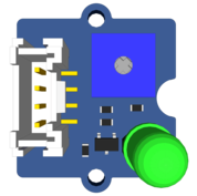 111 |
112 | ## Grove Buzzer Module (5V only)
113 |
114 | This module is a piezo buzzer that will emit a tone when the data line is
115 | driven HIGH, or can be made to play notes and effects by connecting it to a
116 | pulse-width modulation (PWM) output.
117 |
118 |
111 |
112 | ## Grove Buzzer Module (5V only)
113 |
114 | This module is a piezo buzzer that will emit a tone when the data line is
115 | driven HIGH, or can be made to play notes and effects by connecting it to a
116 | pulse-width modulation (PWM) output.
117 |
118 |  119 |
120 | ## Grove Rotary Angle Sensor Module (3.3V/5V)
121 |
122 | This Grove module outputs an analog signal between 0V and VCC based on
123 | the position of the potentiometer. It has an angular range of 300 degrees.
124 |
125 |
119 |
120 | ## Grove Rotary Angle Sensor Module (3.3V/5V)
121 |
122 | This Grove module outputs an analog signal between 0V and VCC based on
123 | the position of the potentiometer. It has an angular range of 300 degrees.
124 |
125 |  126 |
127 | ## Grove Sound Sensor (5V only)
128 |
129 | This is a sound sensing module with a simple microphone. It can be used to
130 | detect the volume of sound in the area. The resistance of the sensor
131 | decreases as the level of sound increases.
132 |
133 |
126 |
127 | ## Grove Sound Sensor (5V only)
128 |
129 | This is a sound sensing module with a simple microphone. It can be used to
130 | detect the volume of sound in the area. The resistance of the sensor
131 | decreases as the level of sound increases.
132 |
133 |  134 |
135 | ## Grove Light Sensor (3.3V/5V)
136 |
137 | This module detects the intensity of light shining on the sensor. The
138 | resistance of the sensor decreases as the amount of illumination increases.
139 |
140 |
134 |
135 | ## Grove Light Sensor (3.3V/5V)
136 |
137 | This module detects the intensity of light shining on the sensor. The
138 | resistance of the sensor decreases as the amount of illumination increases.
139 |
140 |  141 |
142 | ## Grove Servo (5V only)
143 |
144 | The Grove servo is an actuator that is controlled by a PWM signal. The angle
145 | of the servo can be adjusted by changing the pulse width of the input PWM
146 | signal.
147 |
148 |
141 |
142 | ## Grove Servo (5V only)
143 |
144 | The Grove servo is an actuator that is controlled by a PWM signal. The angle
145 | of the servo can be adjusted by changing the pulse width of the input PWM
146 | signal.
147 |
148 |  149 |
150 | ## Grove Relay (3.3V/5V)
151 |
152 | The Grove Relay has a normally-open SPST relay that is controlled
153 | by a single digital pin. It can be used to control power at much
154 | higher voltages that the Sensors mezzanine can handle. When the
155 | signal is LOW the relay is open. When it is driven HIGH the relay
156 | will close.
157 | Use it to control lights and equipment at up to 250V at 10 amps,
158 | but be careful when working with mains voltages.
159 |
160 |
149 |
150 | ## Grove Relay (3.3V/5V)
151 |
152 | The Grove Relay has a normally-open SPST relay that is controlled
153 | by a single digital pin. It can be used to control power at much
154 | higher voltages that the Sensors mezzanine can handle. When the
155 | signal is LOW the relay is open. When it is driven HIGH the relay
156 | will close.
157 | Use it to control lights and equipment at up to 250V at 10 amps,
158 | but be careful when working with mains voltages.
159 |
160 | 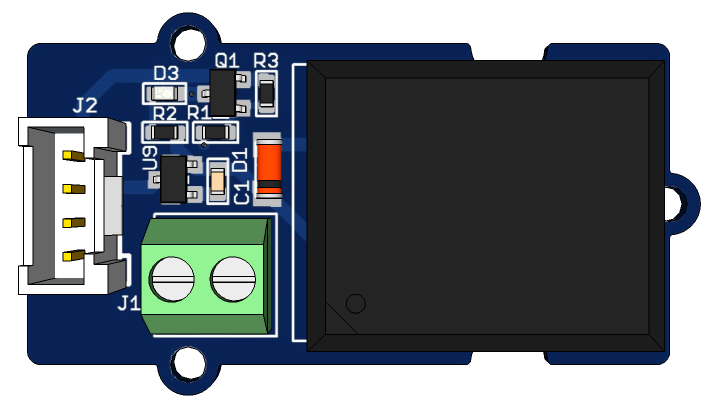 161 |
162 | ## Grove Temperature and Humidity Sensor (3.3V/5V)
163 |
164 | This Grove module is a high accuracy temperature and humidity
165 | sensor.
166 |
167 |
161 |
162 | ## Grove Temperature and Humidity Sensor (3.3V/5V)
163 |
164 | This Grove module is a high accuracy temperature and humidity
165 | sensor.
166 |
167 |  168 |
169 | ## Grove RGB Backlight LCD (5V only)
170 |
171 | This is a great little display module that is easy to control. It is a
172 | 16x2 character display with an RGB backlight controller so you can
173 | set it to whatever colour you like. This module is controlled using
174 | the I2C bus.
175 |
176 |
168 |
169 | ## Grove RGB Backlight LCD (5V only)
170 |
171 | This is a great little display module that is easy to control. It is a
172 | 16x2 character display with an RGB backlight controller so you can
173 | set it to whatever colour you like. This module is controlled using
174 | the I2C bus.
175 |
176 |  177 |
178 | [Back to top](#table-of-contents)
179 |
180 | ***
181 |
182 | # Introduction to the 96Boards Sensors Mezzanine
183 |
184 | The 96Boards Sensors Mezzanine board included in this kit is an IO adapter for connecting
185 | sensors, actuators and other devices to any 96Boards baseboard. The Sensors mezzanine
186 | has exactly the same footprint as a standard size 96Boards Consumer Edition baseboard and
187 | fits perfectly on top. Sensors and other devices are connected to the board via 4 pin Grove
188 | connectors or via the Arduino compatible shield socket.
189 | Additionally, the Sensors mezzanine has a USB to UART adapter for accessing the 96Boards
190 | UART console.
191 |
192 | **Features**
193 |
194 |
177 |
178 | [Back to top](#table-of-contents)
179 |
180 | ***
181 |
182 | # Introduction to the 96Boards Sensors Mezzanine
183 |
184 | The 96Boards Sensors Mezzanine board included in this kit is an IO adapter for connecting
185 | sensors, actuators and other devices to any 96Boards baseboard. The Sensors mezzanine
186 | has exactly the same footprint as a standard size 96Boards Consumer Edition baseboard and
187 | fits perfectly on top. Sensors and other devices are connected to the board via 4 pin Grove
188 | connectors or via the Arduino compatible shield socket.
189 | Additionally, the Sensors mezzanine has a USB to UART adapter for accessing the 96Boards
190 | UART console.
191 |
192 | **Features**
193 |
194 |  195 |
196 | 1. Low Speed Expansion connector
197 | 2. USB UART console connector
198 | 3. Reset and Power buttons
199 | 4. 5V I2C Grove connectors
200 | 5. 5V GPIO Grove connector
201 | 6. 3.3V I2C Grove connectors
202 | 7. 3.3V GPIO Grove connectors
203 | 8. ATMEGA D3-D7 Grove connectors
204 | 9. ATMEGA A0-A2 Grove connectors
205 | 10. ATMEGA I2C Grove connector
206 | 11. ATMEGA Arduino compatible socket
207 | 12. ATMEGA Reset and Power LEDs
208 |
209 | [Back to top](#table-of-contents)
210 |
211 | ***
212 |
213 | # Setting up the Sensors Mezzanine
214 |
215 | ## Step 1: Install Debian Operating System
216 |
217 | If you haven’t already, start with installing the latest Debian image on your 96Boards
218 | baseboard. You can find instructions for installing Debian in your baseboard’s user guide.
219 |
220 | Installing Debian on the CircuitCo or LeMaker HiKey:
221 |
222 | https://www.96boards.org/documentation/ConsumerEdition/HiKey/Installation/
223 |
224 | Qualcomm Dragonboard 410C User Guide:
225 |
226 | https://www.96boards.org/documentation/ConsumerEdition/DragonBoard-410c/Installation/
227 |
228 | ## Step 2: Attach Sensors Adapter
229 |
230 | **STOP:** Before continuing, make sure to intall the 4 mounting standoffs included in the kit onto the sensor mezzanine as shown in the picture below to prevent the electrical damage to the mezzanine and/or the 96Board:
231 |
195 |
196 | 1. Low Speed Expansion connector
197 | 2. USB UART console connector
198 | 3. Reset and Power buttons
199 | 4. 5V I2C Grove connectors
200 | 5. 5V GPIO Grove connector
201 | 6. 3.3V I2C Grove connectors
202 | 7. 3.3V GPIO Grove connectors
203 | 8. ATMEGA D3-D7 Grove connectors
204 | 9. ATMEGA A0-A2 Grove connectors
205 | 10. ATMEGA I2C Grove connector
206 | 11. ATMEGA Arduino compatible socket
207 | 12. ATMEGA Reset and Power LEDs
208 |
209 | [Back to top](#table-of-contents)
210 |
211 | ***
212 |
213 | # Setting up the Sensors Mezzanine
214 |
215 | ## Step 1: Install Debian Operating System
216 |
217 | If you haven’t already, start with installing the latest Debian image on your 96Boards
218 | baseboard. You can find instructions for installing Debian in your baseboard’s user guide.
219 |
220 | Installing Debian on the CircuitCo or LeMaker HiKey:
221 |
222 | https://www.96boards.org/documentation/ConsumerEdition/HiKey/Installation/
223 |
224 | Qualcomm Dragonboard 410C User Guide:
225 |
226 | https://www.96boards.org/documentation/ConsumerEdition/DragonBoard-410c/Installation/
227 |
228 | ## Step 2: Attach Sensors Adapter
229 |
230 | **STOP:** Before continuing, make sure to intall the 4 mounting standoffs included in the kit onto the sensor mezzanine as shown in the picture below to prevent the electrical damage to the mezzanine and/or the 96Board:
231 |  232 |
233 | Remove power and connect the sensors mezzanine to the baseboard. Use the 7mm
234 | standoffs included in this kit to keep the boards the correct distance apart.
235 |
236 | > WARNING: Make sure the expansion connector is correctly lined up before
237 | applying power. Connecting it incorrectly will short the +8-18V power supply
238 | rail directly to low voltage IO pins and will destroy your Sensors adapter. It
239 | may also damage your baseboard.
240 |
241 | ## Step 3 Get a command prompt
242 |
243 | **Option 1: Connect a monitor, keyboard and mouse**
244 | The 96Boards Debian images come with a desktop environment available for download (such as LXQt). It
245 | can be used as a normal Linux desktop computer if you attach a keyboard, mouse and
246 | monitor. Use the “Terminal” application to get a command prompt.
247 |
248 | **Option 2: Serial console**
249 | The sensors board has a USB to Serial interface for connecting to the baseboard's serial
250 | console. Use a MicroUSB cable to connect the Sensors board to your computer and use your
251 | favourite console program at 115200 baud to get a command prompt.
252 | For example, using the ‘screen’ program on a Linux machine:
253 |
254 | `$ screen /dev/ttyUSB0 115200`
255 |
256 | Or on OSX:
257 |
258 | `$ screen /dev/tty.usbserial-08-15 115200`
259 |
260 | **Option 3: Secure Shell**
261 | After connecting to the network (see below), you can get a command prompt with SSH:
262 | ```shell
263 | $ ssh linaro@
264 | password:
265 | ```
266 | ## Step 4: Connect to the network
267 |
268 | The examples in this guide require additional software to be installed. The board needs to
269 | be connected to the Internet to download and install the required packages.
270 |
271 | > IMPORTANT: Change the password with the ‘passwd’ command before
272 | connecting to the Internet Otherwise anyone will be able to ssh into your
273 | board using the default password.
274 |
275 | ```shell
276 | $ passwd linaro
277 | Enter new UNIX password:
278 | Retype new UNIX password:
279 | ```
280 | To connect to a wifi network, use the status bar Network icon in the desktop or use the “nmtui” command from the console.
281 |
282 | `$ nmtui # Will give you a list of available wifi networks`
283 |
284 | ## Step 5: Update Debian
285 |
286 | Make sure all of the Debian packages are up to date before installing the packages required to use the Sensors Mezzanine. From a terminal window execute the following:
287 |
288 | ```shell
289 | $ sudo apt-get update
290 | $ sudo apt-get dist-upgrade -u
291 | Do you want to continue? [Y/n] y
292 | ```
293 | ## Step 6: Install extra tool packages
294 |
295 | To run these demos, we’ll install the Debian packages for the standard Linux development tools, the Python environment, and the Arduino toolchain. Then we'll install the MRAA and
296 | UPM packages from source.
297 |
298 | ```shell
299 | $ sudo apt-get install arduino-mk arduino git build-essential autoconf libtool swig3.0 python-dev cmake pkg-config libpcre3-dev
300 | $ sudo apt-get clean
301 | ```
302 | Now let's install node and npm
303 | ```
304 | sudo apt-get install curl
305 | curl -sL https://deb.nodesource.com/setup_8.x | sudo bash -
306 | sudo apt-get install nodejs
307 | ```
308 | check to make sure installed
309 | ```
310 | $ node -v
311 | v8.9.1
312 | $ npm -v
313 | v5.5.1
314 | ```
315 |
316 | ## Install I/O Libaries
317 | For the purposes of these sample excercises, the user needs to install the following packages to build from source:
318 |
319 | ```shell
320 | $ sudo apt-get install libsoc-dev
321 | # Note: install libsoc prior to libmraa
322 | $ sudo apt-get install libmraa-dev
323 | # Note: install libmraa prior to libmupm
324 | $ sudo apt-get install libupm-dev
325 | ```
326 |
327 | There is a [blog on the 96boards website](https://www.96boards.org/search/?q=libmraa&fields.label=96Boards) entitled "How do you install 96BoardGPIO, libsoc and libmraa on a new image?" that goes into more detail on how to install them, but the below instructions should work. Also note there may be cases where it's required to update these libraries even if they are shown as being already installed.
328 |
329 |
330 | ## Step 7: Configure the software
331 |
332 | The last step is to install some configuration files so that the development tools know
333 | which devices to uses. Fetch the 96boards-tools package and install the provided
334 | configuration files:
335 |
336 | ```shell
337 | $ sudo adduser linaro i2c # Allow the normal user to perform i2c operations
338 | $ git clone https://github.com/96boards/96boards-tools
339 | $ sudo cp 96boards-tools/70-96boards-common.rules /etc/udev/rules.d/
340 | $ cat | sudo tee /etc/profile.d/96boards-sensors.sh << EOF
341 | export JAVA_TOOL_OPTIONS="-Dgnu.io.rxtx.SerialPorts=/dev/tty96B0"
342 | export MONITOR_PORT=/dev/tty96B0
343 | export PYTHONPATH="$PYTHONPATH:/usr/local/lib/python2.7/site-packages"
344 | EOF
345 | $ sudo cp /etc/profile.d/96boards-sensors.sh /etc/X11/Xsession.d/96boardssensors
346 | ```
347 |
348 | Now reboot the system to pick up all the changes
349 |
350 | `$ sudo reboot`
351 |
352 | ## Step 8: Fetch the sample code for projects in this guide
353 |
354 | `$ git clone https://github.com/96boards/Starter_Kit_for_96Boards`
355 |
356 |
357 | ***
358 |
359 | # Using your Sensors Board
360 |
361 | The Sensor mezzanine has connectors for several different types of IO. Some connectors
362 | are directly controlled by Linux on the baseboard, while others are controlled by the
363 | ATMEGA microcontroller. This section describes how to use the each of the IO connectors.
364 |
365 | ## Using Baseboard I2C
366 |
367 | 96Boards defines two I2C busses named I2C0 and I2C1, and there are 2 Grove connectors for
368 | each I2C bus. On the sensors mezzanine, I2C0 is wired for 5V devices, and I2C1 is wired for
369 | 3.3V devices. When connecting an I2C module, you should check what voltage it requires
370 | and use the appropriate connector.
371 | I2C0 and I2C1 can be directly controlled from a Linux program. The MRAA library provides
372 | functions for performing I2C transactions. The Hello World example in this guide
373 | demonstrates how to use an I2C device with Linux.
374 |
375 | ## Using Baseboard GPIO
376 |
377 | 96Boards defines 12 GPIO pins labeled A through L. The Sensors board connects GPIOs A & B
378 | to the “AB” Grove connector via a 5V level shifter. It also connects GPIOs E through L to
379 | Grove connectors EF, GH, IJ and KL via a 3.3V level shifter.
380 |
381 | > WARNING: The GPIO level shifters are designed for high-speed signals but
382 | have very little current drive capacity. Some Grove modules draw more
383 | current than the level shifter can supply and causes oscillation on the line.
384 | For example, the Grove LED module does not work correctly, but the Grove
385 | relay works fine. If you have trouble with a Grove module on a GPIO line, try
386 | controlling it from the microcontroller instead.
387 |
388 | Linux GPIOs can be directly controlled from a Linux program. The MRAA library provides
389 | functions for performing GPIO transactions. GPIOs can also be controlled directly from the
390 | shell by manipulating files in the /sys/class/gpio directory.
391 |
392 | ## Using ATMEGA IO
393 |
394 | The five blue 0.1” Arduino shield connectors (P2-P6), and the 11 Grove connectors (D3-D7, A0-
395 | A2, and AI2C) are connected to the Atmel ATMEGA328P microcontroller. These connectors
396 | are not directly accessible from a Linux program. Instead, you can program the
397 | microcontroller with software to control the connectors and communicate with a Linux
398 | program via the serial port.
399 |
400 | The microcontroller is compatible with the Arduino UNO. It can run Arduino sketches, be
401 | programmed with the Arduino tools, and can be used with Arduino shields. Everything that
402 | works with an Arduino board will work with the Sensors board, but there are a few things to
403 | be aware of.
404 |
405 | **Releasing ATMEGA from reset**
406 | The ATMEGA reset signal is wired to the serial port RTS line. Avrdude (the ATMEGA
407 | programmer) toggles the RTS signal to reset the ATMEGA at various points in the
408 | programming cycle. However, it often leaves the ATMEGA in reset after programming is
409 | complete. Reset will be released when a program (ie. terminal emulator) opens the serial
410 | device, but it can also be manually controlled by using the following stty commands:
411 |
412 | ```shell
413 | $ stty -F /dev/tty96B0 -hupcl # Release ATMEGA from reset
414 | $ stty -F /dev/tty96B0 hupcl # Place ATMEGA into reset
415 | ```
416 |
417 | **Using Command Line Tools**
418 | Often the easiest way to load an Arduino sketch into the ATMEGA is to use the command
419 | line. The following example will load and run the example Blink sketch using only the
420 | command line:
421 |
422 | ```shell
423 | $ mkdir -p sketchbook/Blink
424 | $ cd sketchbook/Blink
425 | $ cp /usr/share/arduino/examples/01.Basics/Blink/Blink.ino .
426 | $ ln -s /usr/share/arduino/Arduino.mk Makefile
427 | $ make upload reset_stty # The reset_stty target releases reset
428 | ```
429 | Once you execute the above command sequence you should see the led on the sensor mezzanine blinking on and off in 1 second intervals. You can now edit `Blink.ino` with your text editor of choice and modify the delay(1000) command, change it to delay(500) for example, rerun the `make upload reset_stty` command, and the led should blink twice as fast. If this is working, you are now ready to go through the excercises!
430 |
431 | You can also use the “make monitor” command to connect the terminal to the serial port
432 | which will also release the ATMEGA from reset. The serial connection can be used as an IO
433 | channel between Linux and sketches running on the ATMEGA.
434 |
435 | [Back to top](#table-of-contents)
436 |
437 | ***
438 |
439 | # Example Project - Hello World with the RGB LCD
440 |
441 | This is an example of how to display text on the Grove RGB LCD module and change the
442 | color of the backlight. The example is written in C++, but could easily be implemented
443 | using Python or Java.
444 |
445 | ## Step 1: Setup the Hardware
446 |
447 | Connect the Groce RGB LCD to either of the I2C0 Grove connectors
448 |
449 |
232 |
233 | Remove power and connect the sensors mezzanine to the baseboard. Use the 7mm
234 | standoffs included in this kit to keep the boards the correct distance apart.
235 |
236 | > WARNING: Make sure the expansion connector is correctly lined up before
237 | applying power. Connecting it incorrectly will short the +8-18V power supply
238 | rail directly to low voltage IO pins and will destroy your Sensors adapter. It
239 | may also damage your baseboard.
240 |
241 | ## Step 3 Get a command prompt
242 |
243 | **Option 1: Connect a monitor, keyboard and mouse**
244 | The 96Boards Debian images come with a desktop environment available for download (such as LXQt). It
245 | can be used as a normal Linux desktop computer if you attach a keyboard, mouse and
246 | monitor. Use the “Terminal” application to get a command prompt.
247 |
248 | **Option 2: Serial console**
249 | The sensors board has a USB to Serial interface for connecting to the baseboard's serial
250 | console. Use a MicroUSB cable to connect the Sensors board to your computer and use your
251 | favourite console program at 115200 baud to get a command prompt.
252 | For example, using the ‘screen’ program on a Linux machine:
253 |
254 | `$ screen /dev/ttyUSB0 115200`
255 |
256 | Or on OSX:
257 |
258 | `$ screen /dev/tty.usbserial-08-15 115200`
259 |
260 | **Option 3: Secure Shell**
261 | After connecting to the network (see below), you can get a command prompt with SSH:
262 | ```shell
263 | $ ssh linaro@
264 | password:
265 | ```
266 | ## Step 4: Connect to the network
267 |
268 | The examples in this guide require additional software to be installed. The board needs to
269 | be connected to the Internet to download and install the required packages.
270 |
271 | > IMPORTANT: Change the password with the ‘passwd’ command before
272 | connecting to the Internet Otherwise anyone will be able to ssh into your
273 | board using the default password.
274 |
275 | ```shell
276 | $ passwd linaro
277 | Enter new UNIX password:
278 | Retype new UNIX password:
279 | ```
280 | To connect to a wifi network, use the status bar Network icon in the desktop or use the “nmtui” command from the console.
281 |
282 | `$ nmtui # Will give you a list of available wifi networks`
283 |
284 | ## Step 5: Update Debian
285 |
286 | Make sure all of the Debian packages are up to date before installing the packages required to use the Sensors Mezzanine. From a terminal window execute the following:
287 |
288 | ```shell
289 | $ sudo apt-get update
290 | $ sudo apt-get dist-upgrade -u
291 | Do you want to continue? [Y/n] y
292 | ```
293 | ## Step 6: Install extra tool packages
294 |
295 | To run these demos, we’ll install the Debian packages for the standard Linux development tools, the Python environment, and the Arduino toolchain. Then we'll install the MRAA and
296 | UPM packages from source.
297 |
298 | ```shell
299 | $ sudo apt-get install arduino-mk arduino git build-essential autoconf libtool swig3.0 python-dev cmake pkg-config libpcre3-dev
300 | $ sudo apt-get clean
301 | ```
302 | Now let's install node and npm
303 | ```
304 | sudo apt-get install curl
305 | curl -sL https://deb.nodesource.com/setup_8.x | sudo bash -
306 | sudo apt-get install nodejs
307 | ```
308 | check to make sure installed
309 | ```
310 | $ node -v
311 | v8.9.1
312 | $ npm -v
313 | v5.5.1
314 | ```
315 |
316 | ## Install I/O Libaries
317 | For the purposes of these sample excercises, the user needs to install the following packages to build from source:
318 |
319 | ```shell
320 | $ sudo apt-get install libsoc-dev
321 | # Note: install libsoc prior to libmraa
322 | $ sudo apt-get install libmraa-dev
323 | # Note: install libmraa prior to libmupm
324 | $ sudo apt-get install libupm-dev
325 | ```
326 |
327 | There is a [blog on the 96boards website](https://www.96boards.org/search/?q=libmraa&fields.label=96Boards) entitled "How do you install 96BoardGPIO, libsoc and libmraa on a new image?" that goes into more detail on how to install them, but the below instructions should work. Also note there may be cases where it's required to update these libraries even if they are shown as being already installed.
328 |
329 |
330 | ## Step 7: Configure the software
331 |
332 | The last step is to install some configuration files so that the development tools know
333 | which devices to uses. Fetch the 96boards-tools package and install the provided
334 | configuration files:
335 |
336 | ```shell
337 | $ sudo adduser linaro i2c # Allow the normal user to perform i2c operations
338 | $ git clone https://github.com/96boards/96boards-tools
339 | $ sudo cp 96boards-tools/70-96boards-common.rules /etc/udev/rules.d/
340 | $ cat | sudo tee /etc/profile.d/96boards-sensors.sh << EOF
341 | export JAVA_TOOL_OPTIONS="-Dgnu.io.rxtx.SerialPorts=/dev/tty96B0"
342 | export MONITOR_PORT=/dev/tty96B0
343 | export PYTHONPATH="$PYTHONPATH:/usr/local/lib/python2.7/site-packages"
344 | EOF
345 | $ sudo cp /etc/profile.d/96boards-sensors.sh /etc/X11/Xsession.d/96boardssensors
346 | ```
347 |
348 | Now reboot the system to pick up all the changes
349 |
350 | `$ sudo reboot`
351 |
352 | ## Step 8: Fetch the sample code for projects in this guide
353 |
354 | `$ git clone https://github.com/96boards/Starter_Kit_for_96Boards`
355 |
356 |
357 | ***
358 |
359 | # Using your Sensors Board
360 |
361 | The Sensor mezzanine has connectors for several different types of IO. Some connectors
362 | are directly controlled by Linux on the baseboard, while others are controlled by the
363 | ATMEGA microcontroller. This section describes how to use the each of the IO connectors.
364 |
365 | ## Using Baseboard I2C
366 |
367 | 96Boards defines two I2C busses named I2C0 and I2C1, and there are 2 Grove connectors for
368 | each I2C bus. On the sensors mezzanine, I2C0 is wired for 5V devices, and I2C1 is wired for
369 | 3.3V devices. When connecting an I2C module, you should check what voltage it requires
370 | and use the appropriate connector.
371 | I2C0 and I2C1 can be directly controlled from a Linux program. The MRAA library provides
372 | functions for performing I2C transactions. The Hello World example in this guide
373 | demonstrates how to use an I2C device with Linux.
374 |
375 | ## Using Baseboard GPIO
376 |
377 | 96Boards defines 12 GPIO pins labeled A through L. The Sensors board connects GPIOs A & B
378 | to the “AB” Grove connector via a 5V level shifter. It also connects GPIOs E through L to
379 | Grove connectors EF, GH, IJ and KL via a 3.3V level shifter.
380 |
381 | > WARNING: The GPIO level shifters are designed for high-speed signals but
382 | have very little current drive capacity. Some Grove modules draw more
383 | current than the level shifter can supply and causes oscillation on the line.
384 | For example, the Grove LED module does not work correctly, but the Grove
385 | relay works fine. If you have trouble with a Grove module on a GPIO line, try
386 | controlling it from the microcontroller instead.
387 |
388 | Linux GPIOs can be directly controlled from a Linux program. The MRAA library provides
389 | functions for performing GPIO transactions. GPIOs can also be controlled directly from the
390 | shell by manipulating files in the /sys/class/gpio directory.
391 |
392 | ## Using ATMEGA IO
393 |
394 | The five blue 0.1” Arduino shield connectors (P2-P6), and the 11 Grove connectors (D3-D7, A0-
395 | A2, and AI2C) are connected to the Atmel ATMEGA328P microcontroller. These connectors
396 | are not directly accessible from a Linux program. Instead, you can program the
397 | microcontroller with software to control the connectors and communicate with a Linux
398 | program via the serial port.
399 |
400 | The microcontroller is compatible with the Arduino UNO. It can run Arduino sketches, be
401 | programmed with the Arduino tools, and can be used with Arduino shields. Everything that
402 | works with an Arduino board will work with the Sensors board, but there are a few things to
403 | be aware of.
404 |
405 | **Releasing ATMEGA from reset**
406 | The ATMEGA reset signal is wired to the serial port RTS line. Avrdude (the ATMEGA
407 | programmer) toggles the RTS signal to reset the ATMEGA at various points in the
408 | programming cycle. However, it often leaves the ATMEGA in reset after programming is
409 | complete. Reset will be released when a program (ie. terminal emulator) opens the serial
410 | device, but it can also be manually controlled by using the following stty commands:
411 |
412 | ```shell
413 | $ stty -F /dev/tty96B0 -hupcl # Release ATMEGA from reset
414 | $ stty -F /dev/tty96B0 hupcl # Place ATMEGA into reset
415 | ```
416 |
417 | **Using Command Line Tools**
418 | Often the easiest way to load an Arduino sketch into the ATMEGA is to use the command
419 | line. The following example will load and run the example Blink sketch using only the
420 | command line:
421 |
422 | ```shell
423 | $ mkdir -p sketchbook/Blink
424 | $ cd sketchbook/Blink
425 | $ cp /usr/share/arduino/examples/01.Basics/Blink/Blink.ino .
426 | $ ln -s /usr/share/arduino/Arduino.mk Makefile
427 | $ make upload reset_stty # The reset_stty target releases reset
428 | ```
429 | Once you execute the above command sequence you should see the led on the sensor mezzanine blinking on and off in 1 second intervals. You can now edit `Blink.ino` with your text editor of choice and modify the delay(1000) command, change it to delay(500) for example, rerun the `make upload reset_stty` command, and the led should blink twice as fast. If this is working, you are now ready to go through the excercises!
430 |
431 | You can also use the “make monitor” command to connect the terminal to the serial port
432 | which will also release the ATMEGA from reset. The serial connection can be used as an IO
433 | channel between Linux and sketches running on the ATMEGA.
434 |
435 | [Back to top](#table-of-contents)
436 |
437 | ***
438 |
439 | # Example Project - Hello World with the RGB LCD
440 |
441 | This is an example of how to display text on the Grove RGB LCD module and change the
442 | color of the backlight. The example is written in C++, but could easily be implemented
443 | using Python or Java.
444 |
445 | ## Step 1: Setup the Hardware
446 |
447 | Connect the Groce RGB LCD to either of the I2C0 Grove connectors
448 |
449 |  450 |
451 | ## Step 2: Write the Software
452 |
453 | Save the following as rgb_lcd_demo.cpp in a working directory on your 96boards
454 | baseboard. This below source is also in the rgb_lcd_demo directory in this repo.
455 |
456 | ```shelldpk
457 | #include
458 | #include "upm/jhd1313m1.hpp"
459 |
460 | #define I2C_BUS 0
461 | #define RGB_WHT 0xff,0xff,0xff
462 | #define RGB_RED 0xff,0x00,0x00
463 | #define RGB_GRN 0x00,0xff,0x00
464 | #define RGB_BLU 0x00,0x00,0xff
465 | #define SLEEP_TIME 2
466 |
467 | using namespace std;
468 | upm::Jhd1313m1* lcd;
469 |
470 | void display(string str1, string str2, int red, int green, int blue)
471 | {
472 | lcd->clear();
473 | lcd->setColor(red, green, blue);
474 | lcd->setCursor(0,0); /* first row */
475 | lcd->write(str1);
476 | lcd->setCursor(1,2); /* second row */
477 | lcd->write(str2);
478 | sleep(SLEEP_TIME);
479 | }
480 |
481 | int main(int argc, char* argv[])
482 | {
483 | string str1 = "96Boards!";
484 | string str2 = "Grove Sensors!";
485 | string str3 = "Linaro!";
486 |
487 | lcd = new upm::Jhd1313m1(I2C_BUS, 0x3e, 0x62);
488 |
489 | if ((argc >= 2) && (argv[1] != NULL))
490 | str1 = argv[1];
491 | if ((argc >= 3) && (argv[2] != NULL))
492 | str2 = argv[2];
493 | if ((argc >= 4) && (argv[3] != NULL))
494 | str3 = argv[3];
495 |
496 | while (true) {
497 | display(str1, "Red", RGB_RED);
498 | display(str2, "Green", RGB_GRN);
499 | display(str3, "Blue", RGB_BLU);
500 | }
501 | delete lcd;
502 | return 0;
503 | }
504 | ```
505 | ## Step 3: Make the Demo
506 |
507 | Enter the following from the same directory the sample code is located.
508 | ```shell
509 | $ g++ rgb_lcd_demo.cpp -o rgb_lcd_demo -g -Wall -lupm-i2clcd
510 | ```
511 | OR
512 | ```shell
513 | $ make
514 | ```
515 |
516 | ## Step 4: Run the demo
517 | ```shell
518 | $ ./rgb_lcd_demo
519 | ```
520 |
521 | The LCD will show some sample messages and the backlight will cycle between red, blue
522 | and green.
523 |
524 | [Back to top](#table-of-contents)
525 |
526 | ***
527 |
528 | # Example Project - Touch Sensor and Relay
529 |
530 | Build a system that toggles a relay on and off when the touch sensor is tapped using Linux
531 | GPIO IO.
532 |
533 | The pins on connectors G1 through G5 are connected to GPIO pins on the baseboard and
534 | can be directly controlled from Linux. In this project, the application reads the state of the
535 | touch sensor from GPIO-G on connector G3, and toggles the relay by driving GPIO-E on
536 | connector G2. Each time the touch sensors is tapped, the relay will toggle between on and
537 | off.
538 |
539 | ## Step 1: Setup the Hardware
540 |
541 | - Attach the relay to G2
542 | - Attach the touch sensor to G3
543 |
544 |
450 |
451 | ## Step 2: Write the Software
452 |
453 | Save the following as rgb_lcd_demo.cpp in a working directory on your 96boards
454 | baseboard. This below source is also in the rgb_lcd_demo directory in this repo.
455 |
456 | ```shelldpk
457 | #include
458 | #include "upm/jhd1313m1.hpp"
459 |
460 | #define I2C_BUS 0
461 | #define RGB_WHT 0xff,0xff,0xff
462 | #define RGB_RED 0xff,0x00,0x00
463 | #define RGB_GRN 0x00,0xff,0x00
464 | #define RGB_BLU 0x00,0x00,0xff
465 | #define SLEEP_TIME 2
466 |
467 | using namespace std;
468 | upm::Jhd1313m1* lcd;
469 |
470 | void display(string str1, string str2, int red, int green, int blue)
471 | {
472 | lcd->clear();
473 | lcd->setColor(red, green, blue);
474 | lcd->setCursor(0,0); /* first row */
475 | lcd->write(str1);
476 | lcd->setCursor(1,2); /* second row */
477 | lcd->write(str2);
478 | sleep(SLEEP_TIME);
479 | }
480 |
481 | int main(int argc, char* argv[])
482 | {
483 | string str1 = "96Boards!";
484 | string str2 = "Grove Sensors!";
485 | string str3 = "Linaro!";
486 |
487 | lcd = new upm::Jhd1313m1(I2C_BUS, 0x3e, 0x62);
488 |
489 | if ((argc >= 2) && (argv[1] != NULL))
490 | str1 = argv[1];
491 | if ((argc >= 3) && (argv[2] != NULL))
492 | str2 = argv[2];
493 | if ((argc >= 4) && (argv[3] != NULL))
494 | str3 = argv[3];
495 |
496 | while (true) {
497 | display(str1, "Red", RGB_RED);
498 | display(str2, "Green", RGB_GRN);
499 | display(str3, "Blue", RGB_BLU);
500 | }
501 | delete lcd;
502 | return 0;
503 | }
504 | ```
505 | ## Step 3: Make the Demo
506 |
507 | Enter the following from the same directory the sample code is located.
508 | ```shell
509 | $ g++ rgb_lcd_demo.cpp -o rgb_lcd_demo -g -Wall -lupm-i2clcd
510 | ```
511 | OR
512 | ```shell
513 | $ make
514 | ```
515 |
516 | ## Step 4: Run the demo
517 | ```shell
518 | $ ./rgb_lcd_demo
519 | ```
520 |
521 | The LCD will show some sample messages and the backlight will cycle between red, blue
522 | and green.
523 |
524 | [Back to top](#table-of-contents)
525 |
526 | ***
527 |
528 | # Example Project - Touch Sensor and Relay
529 |
530 | Build a system that toggles a relay on and off when the touch sensor is tapped using Linux
531 | GPIO IO.
532 |
533 | The pins on connectors G1 through G5 are connected to GPIO pins on the baseboard and
534 | can be directly controlled from Linux. In this project, the application reads the state of the
535 | touch sensor from GPIO-G on connector G3, and toggles the relay by driving GPIO-E on
536 | connector G2. Each time the touch sensors is tapped, the relay will toggle between on and
537 | off.
538 |
539 | ## Step 1: Setup the Hardware
540 |
541 | - Attach the relay to G2
542 | - Attach the touch sensor to G3
543 |
544 |  545 |
546 | ## Step 2: Write the Code
547 |
548 | Save the following code also available in this repo as `./touch_switch/touch_switch.cpp`:
549 |
550 | ```shell
551 | #include
552 | #include
553 | #include "mraa.hpp"
554 |
555 | bool running = true;
556 | bool relay_state = false;
557 | int last_touch;
558 |
559 | void sig_handler(int signo)
560 | {
561 | if (signo == SIGINT)
562 | running = false;
563 | }
564 | int main(int argc, char* argv[])
565 | {
566 | mraa::Gpio* touch_gpio = new mraa::Gpio(29);
567 | mraa::Gpio* relay_gpio = new mraa::Gpio(27);
568 | mraa::Result response;
569 | int touch;
570 |
571 | signal(SIGINT, sig_handler);
572 |
573 | response = touch_gpio->dir(mraa::DIR_IN);
574 | if (response != mraa::SUCCESS)
575 | return 1;
576 | response = relay_gpio->dir(mraa::DIR_OUT);
577 | if (response != mraa::SUCCESS)
578 | return 1;
579 |
580 | relay_gpio->write(relay_state);
581 |
582 | while (running) {
583 | touch = touch_gpio->read();
584 | if (touch == 1 && last_touch == 0) {
585 | relay_state = !relay_state;
586 | response = relay_gpio->write(relay_state);
587 | usleep(100000);
588 | }
589 | last_touch = touch;
590 | }
591 | delete relay_gpio;
592 | delete touch_gpio;
593 | return response;
594 | }
595 | ```
596 | ## Step 3: Build and Run the Demo
597 |
598 | Build the program
599 |
600 | ```shell
601 | $ g++ touch_switch.cpp -o touch_switch -g -Wall -lmraa
602 | ```
603 | OR
604 | ```shell
605 | make
606 | ```
607 | Run the demo
608 | ```shell
609 | $ sudo ./touch_relay # Must be run as root to access GPIOs
610 | ```
611 | When the program is run, the relay will switch between on and off each time you tap the
612 | touch sensor with your finger.
613 |
614 | **Reminder:** Getting an error like this?
615 | ```shell
616 | terminate called after throwing an instance of 'std::invalid_argument'
617 | what(): Invalid GPIO pin specified
618 | Aborted
619 | ```
620 | It's because you must be root to access the I/O! Don't forget the `sudo` when executing the program!
621 |
622 |
623 | [Back to top](#table-of-contents)
624 |
625 | ***
626 |
627 | # Example Project - Drive a Button and LED from the microcontroller
628 |
629 | This example shows how use the microcontroller
630 | read a button and control an LED. We will use the
631 | Arduino toolchain to program the microcontroller.
632 |
633 | ## Step 1: Setup the Hardware
634 |
635 | - Attach the Grove Button to connector A0.
636 | - Attach the Grove LED to connector D3.
637 |
638 |
545 |
546 | ## Step 2: Write the Code
547 |
548 | Save the following code also available in this repo as `./touch_switch/touch_switch.cpp`:
549 |
550 | ```shell
551 | #include
552 | #include
553 | #include "mraa.hpp"
554 |
555 | bool running = true;
556 | bool relay_state = false;
557 | int last_touch;
558 |
559 | void sig_handler(int signo)
560 | {
561 | if (signo == SIGINT)
562 | running = false;
563 | }
564 | int main(int argc, char* argv[])
565 | {
566 | mraa::Gpio* touch_gpio = new mraa::Gpio(29);
567 | mraa::Gpio* relay_gpio = new mraa::Gpio(27);
568 | mraa::Result response;
569 | int touch;
570 |
571 | signal(SIGINT, sig_handler);
572 |
573 | response = touch_gpio->dir(mraa::DIR_IN);
574 | if (response != mraa::SUCCESS)
575 | return 1;
576 | response = relay_gpio->dir(mraa::DIR_OUT);
577 | if (response != mraa::SUCCESS)
578 | return 1;
579 |
580 | relay_gpio->write(relay_state);
581 |
582 | while (running) {
583 | touch = touch_gpio->read();
584 | if (touch == 1 && last_touch == 0) {
585 | relay_state = !relay_state;
586 | response = relay_gpio->write(relay_state);
587 | usleep(100000);
588 | }
589 | last_touch = touch;
590 | }
591 | delete relay_gpio;
592 | delete touch_gpio;
593 | return response;
594 | }
595 | ```
596 | ## Step 3: Build and Run the Demo
597 |
598 | Build the program
599 |
600 | ```shell
601 | $ g++ touch_switch.cpp -o touch_switch -g -Wall -lmraa
602 | ```
603 | OR
604 | ```shell
605 | make
606 | ```
607 | Run the demo
608 | ```shell
609 | $ sudo ./touch_relay # Must be run as root to access GPIOs
610 | ```
611 | When the program is run, the relay will switch between on and off each time you tap the
612 | touch sensor with your finger.
613 |
614 | **Reminder:** Getting an error like this?
615 | ```shell
616 | terminate called after throwing an instance of 'std::invalid_argument'
617 | what(): Invalid GPIO pin specified
618 | Aborted
619 | ```
620 | It's because you must be root to access the I/O! Don't forget the `sudo` when executing the program!
621 |
622 |
623 | [Back to top](#table-of-contents)
624 |
625 | ***
626 |
627 | # Example Project - Drive a Button and LED from the microcontroller
628 |
629 | This example shows how use the microcontroller
630 | read a button and control an LED. We will use the
631 | Arduino toolchain to program the microcontroller.
632 |
633 | ## Step 1: Setup the Hardware
634 |
635 | - Attach the Grove Button to connector A0.
636 | - Attach the Grove LED to connector D3.
637 |
638 |  639 |
640 | ## Step 2: Write the Code
641 |
642 | Create a new directory and save the following program as "test_button_led.ino"
643 |
644 | ```shell
645 | /*
646 | * Example using a button to control an LED
647 | * Copyright (c) 2016 Linaro Ltd.
648 | * SPDX-License-Identifier: BSD-2-Clause
649 | */
650 | int led_pin = 3;
651 | int button_pin = A0;
652 |
653 | void setup()
654 | {
655 | pinMode(led_pin, OUTPUT);
656 | pinMode(button_pin, INPUT);
657 | }
658 |
659 | bool last_button = false;
660 | int led_state = 0;
661 | void loop()
662 | {
663 | bool button = digitalRead(button_pin);
664 | if (last_button != button)
665 | {
666 | if (button) {
667 | led_state = (led_state + 1) % 4;
668 | analogWrite(led_pin, led_state * 0x3f);
669 | }
670 | delay(100);
671 | }
672 | last_button = button;
673 | }
674 | ```
675 | Add the Arduino.mk Makefile to the same directory
676 |
677 | `$ ln -s /usr/share/arduino/Arduino.mk Makefile`
678 |
679 | ## Step 3: Run the Demo
680 |
681 | Build and execute the program
682 |
683 | `$ make upload reset_stty`
684 |
685 | [Back to top](#table-of-contents)
686 |
687 | ***
688 |
689 | # Example Project - Buzzer and Light Sensor
690 |
691 | This example shows how to use the Grove light
692 | sensor and Grove buzzer. While the sensor
693 | detects light, the buzzer will remain silent.
694 | When dark, it will emit noise. In the example,
695 | the buzzer is connected to D4, and the light
696 | sensor to A0; but this can easily be changed by
697 | updating the variables buzzer and sensor to your
698 | prefered pins.
699 |
700 | ## Step 1: Setup Hardware
701 |
702 | - Attach the light sensor to A0
703 | - Attach the buzzer to D4
704 |
705 |
639 |
640 | ## Step 2: Write the Code
641 |
642 | Create a new directory and save the following program as "test_button_led.ino"
643 |
644 | ```shell
645 | /*
646 | * Example using a button to control an LED
647 | * Copyright (c) 2016 Linaro Ltd.
648 | * SPDX-License-Identifier: BSD-2-Clause
649 | */
650 | int led_pin = 3;
651 | int button_pin = A0;
652 |
653 | void setup()
654 | {
655 | pinMode(led_pin, OUTPUT);
656 | pinMode(button_pin, INPUT);
657 | }
658 |
659 | bool last_button = false;
660 | int led_state = 0;
661 | void loop()
662 | {
663 | bool button = digitalRead(button_pin);
664 | if (last_button != button)
665 | {
666 | if (button) {
667 | led_state = (led_state + 1) % 4;
668 | analogWrite(led_pin, led_state * 0x3f);
669 | }
670 | delay(100);
671 | }
672 | last_button = button;
673 | }
674 | ```
675 | Add the Arduino.mk Makefile to the same directory
676 |
677 | `$ ln -s /usr/share/arduino/Arduino.mk Makefile`
678 |
679 | ## Step 3: Run the Demo
680 |
681 | Build and execute the program
682 |
683 | `$ make upload reset_stty`
684 |
685 | [Back to top](#table-of-contents)
686 |
687 | ***
688 |
689 | # Example Project - Buzzer and Light Sensor
690 |
691 | This example shows how to use the Grove light
692 | sensor and Grove buzzer. While the sensor
693 | detects light, the buzzer will remain silent.
694 | When dark, it will emit noise. In the example,
695 | the buzzer is connected to D4, and the light
696 | sensor to A0; but this can easily be changed by
697 | updating the variables buzzer and sensor to your
698 | prefered pins.
699 |
700 | ## Step 1: Setup Hardware
701 |
702 | - Attach the light sensor to A0
703 | - Attach the buzzer to D4
704 |
705 |  706 |
707 | ## Step 2: Write the Code
708 |
709 | Create a new directory and save this file as “Grove_light_buzz.ino”.
710 |
711 | ```shell
712 | //pins used for components
713 | const int buzzer = 4; // Arduino port pin PD4
714 | const int sensor = A0; // Arduino analog ping ADC0
715 |
716 | //this is the threshold value for the light sensor
717 | //to make the light sensor more sensitive, lower this value
718 | int thresholdVal = 400;
719 |
720 | void setup(){
721 | pinMode(sensor, INPUT); // set pin for button input
722 | pinMode(buzzer, OUTPUT); // set pin for buzzer output
723 | }
724 |
725 | void loop(){
726 | int sensorVal = analogRead(sensor);
727 | if (sensorVal < thresholdVal)
728 | digitalWrite(buzzer, HIGH);
729 | else
730 | digitalWrite(buzzer, LOW);
731 | }
732 | ```
733 |
734 | ## Step 3: Run the Demo
735 |
736 | Add the Arduino.mk Makefile to the same directory and build and run the program from the
737 | command line.
738 |
739 | ```shell
740 | $ ln -s /usr/share/arduino/Arduino.mk Makefile
741 | $ make upload reset_stty
742 | ```
743 |
744 | [Back to top](#table-of-contents)
745 |
746 | ***
747 |
748 | # Example Project - Temperature and Humidity Display
749 |
750 | Build a temperature and humidity display.
751 | The microcontroller is used to read the
752 | data stream from the Digital Humidity and
753 | Temperature (DHT) sensor and it passes the
754 | raw data to Linux via the serial port. The
755 | Linux program displays the temperature
756 | and humidity readings on the LCD display.
757 |
758 | ## Step 1: Setup the Hardware
759 |
760 | - Attach the RGB LCD to I2C0
761 | - Attach the temperature and humidity sensor to A0.
762 |
763 |
706 |
707 | ## Step 2: Write the Code
708 |
709 | Create a new directory and save this file as “Grove_light_buzz.ino”.
710 |
711 | ```shell
712 | //pins used for components
713 | const int buzzer = 4; // Arduino port pin PD4
714 | const int sensor = A0; // Arduino analog ping ADC0
715 |
716 | //this is the threshold value for the light sensor
717 | //to make the light sensor more sensitive, lower this value
718 | int thresholdVal = 400;
719 |
720 | void setup(){
721 | pinMode(sensor, INPUT); // set pin for button input
722 | pinMode(buzzer, OUTPUT); // set pin for buzzer output
723 | }
724 |
725 | void loop(){
726 | int sensorVal = analogRead(sensor);
727 | if (sensorVal < thresholdVal)
728 | digitalWrite(buzzer, HIGH);
729 | else
730 | digitalWrite(buzzer, LOW);
731 | }
732 | ```
733 |
734 | ## Step 3: Run the Demo
735 |
736 | Add the Arduino.mk Makefile to the same directory and build and run the program from the
737 | command line.
738 |
739 | ```shell
740 | $ ln -s /usr/share/arduino/Arduino.mk Makefile
741 | $ make upload reset_stty
742 | ```
743 |
744 | [Back to top](#table-of-contents)
745 |
746 | ***
747 |
748 | # Example Project - Temperature and Humidity Display
749 |
750 | Build a temperature and humidity display.
751 | The microcontroller is used to read the
752 | data stream from the Digital Humidity and
753 | Temperature (DHT) sensor and it passes the
754 | raw data to Linux via the serial port. The
755 | Linux program displays the temperature
756 | and humidity readings on the LCD display.
757 |
758 | ## Step 1: Setup the Hardware
759 |
760 | - Attach the RGB LCD to I2C0
761 | - Attach the temperature and humidity sensor to A0.
762 |
763 | 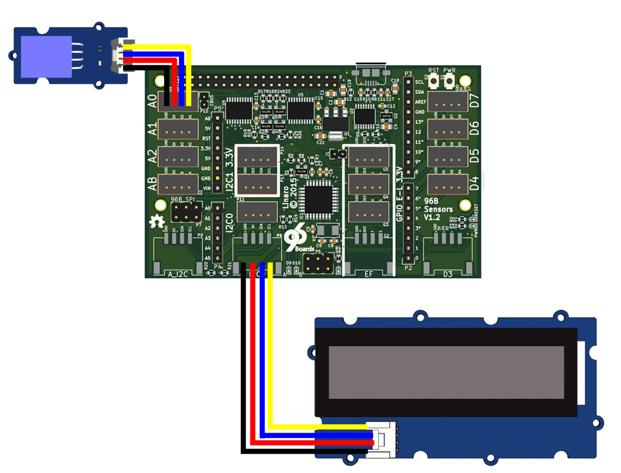 764 |
765 | ## Step 2: Write the Code
766 |
767 | Save the following code as read_dht.ino
768 |
769 | ```shell
770 | #include "DHT.h"
771 |
772 | DHT dht(A0, DHT11);
773 |
774 | void setup()
775 | {
776 | Serial.begin(9600);
777 | dht.begin();
778 | }
779 |
780 | void loop()
781 | {
782 | float h = dht.readHumidity();
783 | float t = dht.readTemperature();
784 |
785 | // check if valid, if NaN (not a number) then something went wrong!
786 | if (isnan(t) || isnan(h)) {
787 | Serial.println("Failed to read from DHT");
788 | return;
789 | }
790 |
791 | Serial.print("Humidity: ");
792 | Serial.print(h);
793 | Serial.print(" %\t");
794 | Serial.print("Temperature: ");
795 | Serial.print(t);
796 | Serial.println(" *C");
797 | delay(2000);
798 | }
799 | ```
800 |
801 | Next save the following code as display as “humid_temp.py”
802 |
803 | ```shell
804 | import serial, pyupm_i2clcd
805 | ard = serial.Serial('/dev/tty96B0', 9600)
806 | lcd = pyupm_i2clcd.Jhd1313m1(0, 0x3e, 0x62)
807 |
808 | def showTemp(humid, temp):
809 | lcd.clear()
810 | lcd.setCursor(0, 0)
811 | lcd.write(humid)
812 | lcd.setCursor(1, 0)
813 | lcd.write("Temp:" + temp + " C")
814 | lcd.setColor(255, 180, 180)
815 |
816 | if __name__ == '__main__':
817 | print("Welcome to the Humidity & Temperature reader!!!")
818 | try:
819 | while True:
820 | ardOut = ard.readline()
821 | if ardOut.find("Humidity:") != -1:
822 | ardHumid = ardOut.split('Temperature')[0]
823 | ardTemp = ardOut.split('Temperature:')[1]
824 | showTemp(ardHumid,ardTemp)
825 | except KeyboardInterrupt:
826 | lcd.setColor(0,0,0)
827 | lcd.clear()
828 | print("CTRL-C!! Exiting...")
829 | ```
830 |
831 | Create a Makefile with the following:
832 |
833 | ```shell
834 | include /usr/share/arduino/Arduino.mk
835 | run: upload
836 | python humid_temp.py
837 | ```
838 |
839 | This example also utilises an additional library to control the DHT component. You’ll need
840 | to clone the following repository, then move the DHT files into your projects directory:
841 |
842 | ```shell
843 | $ git clone https://github.com/Seeed-Studio/Grove_Temperature_And_Humidity_Sensor.git
844 | $ cd Grove_Temperature_And_Humidity_Sensor/
845 | $ mv DHT.* ../
846 | $ cd ..
847 | ```
848 |
849 | ## Step 2: Run the Demo
850 |
851 | To run the program, type in the terminal:
852 |
853 | ```shell
854 | $ PYTHONPATH=$PYTHONPATH:/usr/lib/aarch64-linux-gnu/python2.7/site-packages
855 | $ make run
856 | ```
857 |
858 | And to exit, use Ctrl + C
859 |
860 | ** Potential build errors / work-arounds**
861 | 1) Build Error:
862 | ImportError: No module named pyupm_i2clcd
863 | Makefile:3: recipe for target 'run' failed
864 |
865 | Fix: Need to add path to PYTHONPATH
866 | `PYTHONPATH=$PYTHONPATH:/usr/lib/aarch64-linux-gnu/python2.7/site-packages`
867 |
868 | 2) Build Error
869 | File "/usr/lib/aarch64-linux-gnu/python2.7/site-packages/pyupm_i2clcd.py", line 985
870 | SyntaxError: Non-ASCII character '\xc3' in file /usr/lib/aarch64-linux-gnu/python2.7/site-packages/pyupm_i2clcd.py on line 986, but no encoding declared; see http://python.org/dev/peps/pep-0263/ for details
871 | Makefile:3: recipe for target 'run' failed
872 |
873 | Fix: Add `# coding=utf-8` to first line of /usr/lib/aarch64-linux-gnu/python2.7/site-packages/pyupm_i2clcd.py and save
874 |
875 |
876 | [Back to top](#table-of-contents)
877 |
878 | ***
879 |
880 | # Example Project - Tweeting Doorbell
881 |
882 | In this project, You'll write an application in Python to take input from sensors and
883 | communicate on the Internet. This project creates a “tweeting” doorbell which sends a
884 | message out to twitter every time the button is pressed.
885 |
886 | To send tweets from Python, we need to install an additional library. Use apt-get to install
887 | the “Tweepy” package:
888 |
889 | `$ sudo apt-get install python-tweepy`
890 |
891 | ## Step 1: Setup the Hardware
892 |
893 | - Connect the LED module to D3
894 | - Connect the Button module to D4
895 | - Connect the Buzzer module to D5
896 | - Connect the RGB LCD to I2C0
897 |
898 |
764 |
765 | ## Step 2: Write the Code
766 |
767 | Save the following code as read_dht.ino
768 |
769 | ```shell
770 | #include "DHT.h"
771 |
772 | DHT dht(A0, DHT11);
773 |
774 | void setup()
775 | {
776 | Serial.begin(9600);
777 | dht.begin();
778 | }
779 |
780 | void loop()
781 | {
782 | float h = dht.readHumidity();
783 | float t = dht.readTemperature();
784 |
785 | // check if valid, if NaN (not a number) then something went wrong!
786 | if (isnan(t) || isnan(h)) {
787 | Serial.println("Failed to read from DHT");
788 | return;
789 | }
790 |
791 | Serial.print("Humidity: ");
792 | Serial.print(h);
793 | Serial.print(" %\t");
794 | Serial.print("Temperature: ");
795 | Serial.print(t);
796 | Serial.println(" *C");
797 | delay(2000);
798 | }
799 | ```
800 |
801 | Next save the following code as display as “humid_temp.py”
802 |
803 | ```shell
804 | import serial, pyupm_i2clcd
805 | ard = serial.Serial('/dev/tty96B0', 9600)
806 | lcd = pyupm_i2clcd.Jhd1313m1(0, 0x3e, 0x62)
807 |
808 | def showTemp(humid, temp):
809 | lcd.clear()
810 | lcd.setCursor(0, 0)
811 | lcd.write(humid)
812 | lcd.setCursor(1, 0)
813 | lcd.write("Temp:" + temp + " C")
814 | lcd.setColor(255, 180, 180)
815 |
816 | if __name__ == '__main__':
817 | print("Welcome to the Humidity & Temperature reader!!!")
818 | try:
819 | while True:
820 | ardOut = ard.readline()
821 | if ardOut.find("Humidity:") != -1:
822 | ardHumid = ardOut.split('Temperature')[0]
823 | ardTemp = ardOut.split('Temperature:')[1]
824 | showTemp(ardHumid,ardTemp)
825 | except KeyboardInterrupt:
826 | lcd.setColor(0,0,0)
827 | lcd.clear()
828 | print("CTRL-C!! Exiting...")
829 | ```
830 |
831 | Create a Makefile with the following:
832 |
833 | ```shell
834 | include /usr/share/arduino/Arduino.mk
835 | run: upload
836 | python humid_temp.py
837 | ```
838 |
839 | This example also utilises an additional library to control the DHT component. You’ll need
840 | to clone the following repository, then move the DHT files into your projects directory:
841 |
842 | ```shell
843 | $ git clone https://github.com/Seeed-Studio/Grove_Temperature_And_Humidity_Sensor.git
844 | $ cd Grove_Temperature_And_Humidity_Sensor/
845 | $ mv DHT.* ../
846 | $ cd ..
847 | ```
848 |
849 | ## Step 2: Run the Demo
850 |
851 | To run the program, type in the terminal:
852 |
853 | ```shell
854 | $ PYTHONPATH=$PYTHONPATH:/usr/lib/aarch64-linux-gnu/python2.7/site-packages
855 | $ make run
856 | ```
857 |
858 | And to exit, use Ctrl + C
859 |
860 | ** Potential build errors / work-arounds**
861 | 1) Build Error:
862 | ImportError: No module named pyupm_i2clcd
863 | Makefile:3: recipe for target 'run' failed
864 |
865 | Fix: Need to add path to PYTHONPATH
866 | `PYTHONPATH=$PYTHONPATH:/usr/lib/aarch64-linux-gnu/python2.7/site-packages`
867 |
868 | 2) Build Error
869 | File "/usr/lib/aarch64-linux-gnu/python2.7/site-packages/pyupm_i2clcd.py", line 985
870 | SyntaxError: Non-ASCII character '\xc3' in file /usr/lib/aarch64-linux-gnu/python2.7/site-packages/pyupm_i2clcd.py on line 986, but no encoding declared; see http://python.org/dev/peps/pep-0263/ for details
871 | Makefile:3: recipe for target 'run' failed
872 |
873 | Fix: Add `# coding=utf-8` to first line of /usr/lib/aarch64-linux-gnu/python2.7/site-packages/pyupm_i2clcd.py and save
874 |
875 |
876 | [Back to top](#table-of-contents)
877 |
878 | ***
879 |
880 | # Example Project - Tweeting Doorbell
881 |
882 | In this project, You'll write an application in Python to take input from sensors and
883 | communicate on the Internet. This project creates a “tweeting” doorbell which sends a
884 | message out to twitter every time the button is pressed.
885 |
886 | To send tweets from Python, we need to install an additional library. Use apt-get to install
887 | the “Tweepy” package:
888 |
889 | `$ sudo apt-get install python-tweepy`
890 |
891 | ## Step 1: Setup the Hardware
892 |
893 | - Connect the LED module to D3
894 | - Connect the Button module to D4
895 | - Connect the Buzzer module to D5
896 | - Connect the RGB LCD to I2C0
897 |
898 |  899 |
900 | ## Step 2: Write the Code
901 |
902 | This example requires some extra setup to communicate with Twitter. You will need to have
903 | a twitter account and obtain oauth details from https :// apps . twitter . com by creating an
904 | app. Put the oauth details into a file named keys.py:
905 |
906 | ```shell
907 | consumer_key = “YourConsumerKey”
908 | consumer_secret = “YourConsumerSecret”
909 | access_token = “YourAccessToken”
910 | access_token_secret = “YourAccessSecret”
911 | ```
912 |
913 | Save the following code as tweeting_doorbell.ino:
914 |
915 | ```shell
916 | const int buttonPin = 4;
917 | const int ledPin = 3;
918 | const int buzzerPin = 5;
919 |
920 | void setup() {
921 | pinMode(buttonPin, INPUT);
922 | pinMode(ledPin, OUTPUT);
923 | pinMode(buzzerPin, OUTPUT);
924 | Serial.begin(115200);
925 | Serial.println("waiting");
926 | }
927 |
928 | void loop() {
929 | int pressed = digitalRead(buttonPin);
930 | if (pressed == 1) {
931 | digitalWrite(ledPin, HIGH);
932 | digitalWrite(buzzerPin, HIGH);
933 | Serial.println("tweet");
934 | delay(1000);
935 | digitalWrite(buzzerPin, LOW);
936 | digitalWrite(ledPin, LOW);
937 | }
938 | }
939 | ```
940 |
941 | Save the following code as tweeting_doorbell.py:
942 |
943 | ```shell
944 | import tweepy, serial, datetime, time, keys, pyupm_i2clcd
945 |
946 | auth = tweepy.OAuthHandler(keys.consumer_key,
947 | keys.consumer_secret)
948 | auth.set_access_token(keys.access_token,
949 | keys.access_token_secret)
950 |
951 | api = tweepy.API(auth)
952 | ard = serial.Serial('/dev/tty96B0', 115200)
953 | lcd = pyupm_i2clcd.Jhd1313m1(0, 0x3e, 0x62)
954 |
955 | def tweet():
956 | lcd.clear()
957 | today = datetime.datetime.now()
958 | lcd.setCursor(0, 0)
959 | lcd.write("Ding Dong")
960 | lcd.setCursor(1, 0)
961 | lcd.write(today.strftime('%Y/%m/%d %H:%M:%S'))
962 | lcd.setColor(0, 255, 0)
963 |
964 | msg = '(Chatty Doorbell) Ding dong! Someone was at the door at %s' % \
965 | today.strftime('%d/%m/%Y %H:%M:%S')
966 | print(msg)
967 | api.update_status(msg)
968 | time.sleep(1)
969 |
970 | lcd.setColor(0,0,0)
971 | lcd.clear()
972 |
973 | if __name__ == '__main__':
974 | lcd.clear()
975 | lcd.setColor(0, 0, 0)
976 | print("Welcome to the tweeting doorbell! To quit, press CTRL + C")
977 | try:
978 | while True:
979 | ardOut = ard.readline()
980 | if ardOut.find("tweet") != -1:
981 | tweet()
982 | except KeyboardInterrupt:
983 | print("CTRL-C!! Exiting...")
984 | ```
985 |
986 | Finally, create a Makefile:
987 |
988 | ```shell
989 | include /usr/share/arduino/Arduino.mk
990 | run: upload
991 | python tweeting_doorbell.py
992 | ```
993 |
994 | ## Step 3: Run the Demo
995 |
996 | To run the program, type in terminal:
997 |
998 | ```shell
999 | $ make run
1000 | Welcome to the tweeting doorbell! To quit, press CTRL + C
1001 | (Chatty Doorbell) Ding dong! Someone was at the door at 2016/02/13 00:55:08
1002 | ```
1003 |
1004 | And to exit, use CTRL + C
1005 |
1006 | [Back to top](#table-of-contents)
1007 |
1008 | ***
1009 |
1010 | # Additional Resources
1011 |
1012 | ## Design files
1013 |
1014 | The UART adapter board is an entirely Open Hardware, designed using KiCad, and with all
1015 | of the design files provided under a BSD license. The files can be found on GitHub:
1016 |
1017 | https://github.com/96boards/96boards-sensors
1018 |
1019 | ## More Example Core
1020 |
1021 | There are many of examples of how to interface with sensors in the UPM package. Look in
1022 | the examples/ subdirectory of the UPM repository for examples written in C++, Java,
1023 | Javascript and Python.
1024 |
1025 | https://github.com/intel-iot-devkit/upm
1026 |
1027 | ## Example from other Kits
1028 |
1029 | The examples listed in this section have not been thoroughly tested and may require
1030 | changes to get to work with the 96Boards Sensors Mezzanine. They are included here for
1031 | reference.
1032 |
1033 | **Seeed Studio Grove Starter Kit for Arduino**
1034 | http://www.seeedstudio.com/wiki/Grove_-_Starter_Kit_v3
1035 |
1036 | Just about all of the examples in Seeed Studio’s Arduino starter kit will work with the
1037 | 96Boards Sensor board. You can get the sketch demos from:
1038 |
1039 | https://github.com/Seeed-Studio/Sketchbook_Starter_Kit_for_Arduino
1040 |
1041 | **Dexter Industries GrovePi+ Starter Kit**
1042 |
1043 | http://www.dexterindustries.com/grovepi
1044 |
1045 | The GrovePi+ kit demonstrates how to use the I2C bus to communicate between the
1046 | baseboard and the ATMEGA microcontroller. Many of the examples in the GrovePi+ kit will
1047 | work on the Sensors mezzanine with only minor modifications.
1048 |
1049 | Using the GrovePi+ examples with the Sensors board requires connecting the ATMEGA to the
1050 | I2C0 bus. The Sensors board has two unpopulated resistor pads along the bottom edge of
1051 | the board labelled R20 and R21. Use a soldering iron to put a blob of solder across the pads
1052 | of R20, and another blob over the pads of R21. This will complete the I2C connection
1053 | between the ATMEGA and the baseboard.
1054 |
1055 | You can download the GrovePi+ example software from github:
1056 |
1057 | http://github.com/Dexterlnd/GrovePi
1058 |
1059 | [Back to top](#table-of-contents)
1060 |
1061 | ***
1062 |
--------------------------------------------------------------------------------
/Sensors.pdf:
--------------------------------------------------------------------------------
https://raw.githubusercontent.com/96boards/Sensor_Mezzanine_Getting_Started/6456fdf28c66bb3ab10ed3d4c5ae3d2a0c97952f/Sensors.pdf
--------------------------------------------------------------------------------
/button_led/Makefile:
--------------------------------------------------------------------------------
1 | include /usr/share/arduino/Arduino.mk
2 |
--------------------------------------------------------------------------------
/button_led/button_led.ino:
--------------------------------------------------------------------------------
1 | /*
2 | * Example using a button to control an LED
3 | * Copyright (c) 2016 Linaro Ltd.
4 | * SPDX-License-Identifier: BSD-2-Clause
5 | */
6 | int led_pin = 3;
7 | int button_pin = A0;
8 |
9 | void setup()
10 | {
11 | pinMode(led_pin, OUTPUT);
12 | pinMode(button_pin, INPUT);
13 | }
14 |
15 | bool last_button = false;
16 | int led_state = 0;
17 |
18 | void loop()
19 | {
20 | bool button = digitalRead(button_pin);
21 | if (last_button != button)
22 | {
23 | if (button) {
24 | led_state = (led_state + 1) % 4;
25 | analogWrite(led_pin, led_state * 0x3f);
26 | }
27 | delay(100);
28 | }
29 | last_button = button;
30 | }
31 |
32 |
--------------------------------------------------------------------------------
/humid_temp/DHT.cpp:
--------------------------------------------------------------------------------
1 | /* DHT library
2 |
3 | MIT license
4 | written by Adafruit Industries
5 | */
6 |
7 | #include "DHT.h"
8 | #define NAN 0
9 |
10 | DHT::DHT(uint8_t pin, uint8_t type, uint8_t count) {
11 | _pin = pin;
12 | _type = type;
13 | _count = count;
14 | firstreading = true;
15 | }
16 |
17 | void DHT::begin(void) {
18 | // set up the pins!
19 | pinMode(_pin, INPUT);
20 | digitalWrite(_pin, HIGH);
21 | _lastreadtime = 0;
22 | }
23 |
24 | //boolean S == Scale. True == Farenheit; False == Celcius
25 | float DHT::readTemperature(bool S) {
26 | float f;
27 |
28 | if (read()) {
29 | switch (_type) {
30 | case DHT11:
31 | f = data[2];
32 | if(S)
33 | f = convertCtoF(f);
34 |
35 | return f;
36 | case DHT22:
37 | case DHT21:
38 | f = data[2] & 0x7F;
39 | f *= 256;
40 | f += data[3];
41 | f /= 10;
42 | if (data[2] & 0x80)
43 | f *= -1;
44 | if(S)
45 | f = convertCtoF(f);
46 |
47 | return f;
48 | }
49 | }
50 | Serial.print("Read fail");
51 | return NAN;
52 | }
53 |
54 | float DHT::convertCtoF(float c) {
55 | return c * 9 / 5 + 32;
56 | }
57 |
58 | float DHT::readHumidity(void) {
59 | float f;
60 | if (read()) {
61 | switch (_type) {
62 | case DHT11:
63 | f = data[0];
64 | return f;
65 | case DHT22:
66 | case DHT21:
67 | f = data[0];
68 | f *= 256;
69 | f += data[1];
70 | f /= 10;
71 | return f;
72 | }
73 | }
74 | Serial.print("Read fail");
75 | return NAN;
76 | }
77 |
78 |
79 | boolean DHT::read(void) {
80 | uint8_t laststate = HIGH;
81 | uint8_t counter = 0;
82 | uint8_t j = 0, i;
83 | unsigned long currenttime;
84 |
85 | // pull the pin high and wait 250 milliseconds
86 | digitalWrite(_pin, HIGH);
87 | delay(250);
88 |
89 | currenttime = millis();
90 | if (currenttime < _lastreadtime) {
91 | // ie there was a rollover
92 | _lastreadtime = 0;
93 | }
94 | if (!firstreading && ((currenttime - _lastreadtime) < 2000)) {
95 | return true; // return last correct measurement
96 | //delay(2000 - (currenttime - _lastreadtime));
97 | }
98 | firstreading = false;
99 | /*
100 | Serial.print("Currtime: "); Serial.print(currenttime);
101 | Serial.print(" Lasttime: "); Serial.print(_lastreadtime);
102 | */
103 | _lastreadtime = millis();
104 |
105 | data[0] = data[1] = data[2] = data[3] = data[4] = 0;
106 |
107 | // now pull it low for ~20 milliseconds
108 | pinMode(_pin, OUTPUT);
109 | digitalWrite(_pin, LOW);
110 | delay(20);
111 | //cli();
112 | digitalWrite(_pin, HIGH);
113 | delayMicroseconds(40);
114 | pinMode(_pin, INPUT);
115 |
116 | // read in timings
117 | for ( i=0; i< MAXTIMINGS; i++) {
118 | counter = 0;
119 | while (digitalRead(_pin) == laststate) {
120 | counter++;
121 | delayMicroseconds(1);
122 | if (counter == 255) {
123 | break;
124 | }
125 | }
126 | laststate = digitalRead(_pin);
127 |
128 | if (counter == 255) break;
129 |
130 | // ignore first 3 transitions
131 | if ((i >= 4) && (i%2 == 0)) {
132 | // shove each bit into the storage bytes
133 | data[j/8] <<= 1;
134 | if (counter > _count)
135 | data[j/8] |= 1;
136 | j++;
137 | }
138 |
139 | }
140 |
141 | //sei();
142 |
143 | /*
144 | Serial.println(j, DEC);
145 | Serial.print(data[0], HEX); Serial.print(", ");
146 | Serial.print(data[1], HEX); Serial.print(", ");
147 | Serial.print(data[2], HEX); Serial.print(", ");
148 | Serial.print(data[3], HEX); Serial.print(", ");
149 | Serial.print(data[4], HEX); Serial.print(" =? ");
150 | Serial.println(data[0] + data[1] + data[2] + data[3], HEX);
151 | */
152 |
153 | // check we read 40 bits and that the checksum matches
154 | if ((j >= 40) &&
155 | (data[4] == ((data[0] + data[1] + data[2] + data[3]) & 0xFF)) ) {
156 | return true;
157 | }
158 |
159 |
160 | return false;
161 |
162 | }
163 |
--------------------------------------------------------------------------------
/humid_temp/DHT.h:
--------------------------------------------------------------------------------
1 | #ifndef DHT_H
2 | #define DHT_H
3 | #if ARDUINO >= 100
4 | #include "Arduino.h"
5 | #else
6 | #include "WProgram.h"
7 | #endif
8 |
9 | // 8 MHz(ish) AVR ---------------------------------------------------------
10 | #if (F_CPU >= 7400000UL) && (F_CPU <= 9500000UL)
11 | #define COUNT 3
12 | // 16 MHz(ish) AVR --------------------------------------------------------
13 | #elif (F_CPU >= 15400000UL) && (F_CPU <= 19000000L)
14 | #define COUNT 6
15 | #else
16 | #error "CPU SPEED NOT SUPPORTED"
17 | #endif
18 |
19 | /* DHT library
20 |
21 | MIT license
22 | written by Adafruit Industries
23 | */
24 |
25 | // how many timing transitions we need to keep track of. 2 * number bits + extra
26 | #define MAXTIMINGS 85
27 |
28 | #define DHT11 11
29 | #define DHT22 22
30 | #define DHT21 21
31 | #define AM2301 21
32 |
33 | class DHT {
34 | private:
35 | uint8_t data[6];
36 | uint8_t _pin, _type, _count;
37 | boolean read(void);
38 | unsigned long _lastreadtime;
39 | boolean firstreading;
40 |
41 | public:
42 | DHT(uint8_t pin, uint8_t type, uint8_t count=COUNT);
43 | void begin(void);
44 | float readTemperature(bool S=false);
45 | float convertCtoF(float);
46 | float readHumidity(void);
47 |
48 | };
49 | #endif
50 |
--------------------------------------------------------------------------------
/humid_temp/Makefile:
--------------------------------------------------------------------------------
1 | include /usr/share/arduino/Arduino.mk
2 | run: upload
3 | python humid_temp.py
4 |
5 |
--------------------------------------------------------------------------------
/humid_temp/humid_temp.py:
--------------------------------------------------------------------------------
1 | import serial, pyupm_i2clcd
2 |
3 | ard = serial.Serial('/dev/tty96B0', 9600)
4 | lcd = pyupm_i2clcd.Jhd1313m1(0, 0x3e, 0x62)
5 |
6 | def showTemp(humid, temp):
7 | lcd.clear()
8 | lcd.setCursor(0, 0)
9 | lcd.write(humid)
10 | lcd.setCursor(1, 0)
11 | lcd.write("Temp:" + temp + " C")
12 | lcd.setColor(255, 180, 180)
13 |
14 | if __name__ == '__main__':
15 | print("Welcome to the Humidity & Temperature reader!!!")
16 | try:
17 | while True:
18 | ardOut = ard.readline()
19 | if ardOut.find("Humidity:") != -1:
20 | ardHumid = ardOut.split('Temperature')[0]
21 | ardTemp = ardOut.split('Temperature:')[1]
22 | showTemp(ardHumid,ardTemp)
23 | except KeyboardInterrupt:
24 | lcd.setColor(0,0,0)
25 | lcd.clear()
26 | print("CTRL-C!! Exiting...")
27 |
--------------------------------------------------------------------------------
/humid_temp/read_dht.ino:
--------------------------------------------------------------------------------
1 | #include "DHT.h"
2 |
3 | DHT dht(A0, DHT11);
4 |
5 | void setup()
6 | {
7 | Serial.begin(9600);
8 | dht.begin();
9 | }
10 |
11 | void loop()
12 | {
13 | float h = dht.readHumidity();
14 | float t = dht.readTemperature();
15 |
16 | // check if valid, if NaN (not a number) then something went wrong!
17 | if (isnan(t) || isnan(h)) {
18 | Serial.println("Failed to read from DHT");
19 | return;
20 | }
21 |
22 | Serial.print("Humidity: ");
23 | Serial.print(h);
24 | Serial.print(" %\t");
25 | Serial.print("Temperature: ");
26 | Serial.print(t);
27 | Serial.println(" *C");
28 | delay(2000);
29 | }
30 |
31 |
--------------------------------------------------------------------------------
/light_buzz/Makefile:
--------------------------------------------------------------------------------
1 | include /usr/share/arduino/Arduino.mk
2 |
--------------------------------------------------------------------------------
/light_buzz/light_buzz.ino:
--------------------------------------------------------------------------------
1 | //pins used for components
2 | const int buzzer = 4; // Arduino port pin PD4
3 | const int sensor = A0; // Arduino analog ping ADC0
4 |
5 |
6 | //this is the threshold value for the light sensor
7 | //to make the light sensor more sensitive, lower this value
8 | int thresholdVal = 400;
9 |
10 | void setup(){
11 | pinMode(sensor, INPUT); // set pin for button input
12 | pinMode(buzzer, OUTPUT); // set pin for buzzer output
13 | }
14 |
15 | void loop() {
16 | int sensorVal = analogRead(sensor);
17 | if (sensorVal < thresholdVal)
18 | digitalWrite(buzzer, HIGH);
19 | else
20 | digitalWrite(buzzer, LOW);
21 | }
22 |
23 |
--------------------------------------------------------------------------------
/rgb_lcd_demo/.gitignore:
--------------------------------------------------------------------------------
1 | rgb_lcd_demo
2 |
--------------------------------------------------------------------------------
/rgb_lcd_demo/Makefile:
--------------------------------------------------------------------------------
1 | LDFLAGS=-lupm-i2clcd
2 | CXXFLAGS=-Wall -g
3 | TARGETS=rgb_lcd_demo
4 |
5 | all: ${TARGETS}
6 | clean:
7 | rm -f ${TARGETS}
8 |
--------------------------------------------------------------------------------
/rgb_lcd_demo/rgb_lcd_demo.cpp:
--------------------------------------------------------------------------------
1 | /*
2 | * Author: Akira Tsukamoto
3 | * Copyright (c) 2016 Linaro Ltd.
4 | * All rights reserved.
5 | * SPDX-License-Identifier: BSD-2-Clause
6 | */
7 |
8 | #include
9 | #include "upm/jhd1313m1.hpp"
10 |
11 | #define I2C_BUS 0
12 | #define RGB_WHT 0xff,0xff,0xff
13 | #define RGB_RED 0xff,0x00,0x00
14 | #define RGB_GRN 0x00,0xff,0x00
15 | #define RGB_BLU 0x00,0x00,0xff
16 | #define SLEEP_TIME 2
17 |
18 | using namespace std;
19 | upm::Jhd1313m1* lcd;
20 |
21 | void display(string str1, string str2, int red, int green, int blue)
22 | {
23 | lcd->clear();
24 | lcd->setColor(red, green, blue);
25 | lcd->setCursor(0,0); /* first row */
26 | lcd->write(str1);
27 | lcd->setCursor(1,2); /* second row */
28 | lcd->write(str2);
29 | sleep(SLEEP_TIME);
30 | }
31 |
32 | int main(int argc, char* argv[])
33 | {
34 | string str1 = "96Boards!";
35 | string str2 = "Grove Sensors!";
36 | string str3 = "Linaro!";
37 |
38 | lcd = new upm::Jhd1313m1(I2C_BUS, 0x3e, 0x62);
39 |
40 | if ((argc >= 2) && (argv[1] != NULL))
41 | str1 = argv[1];
42 | if ((argc >= 3) && (argv[2] != NULL))
43 | str2 = argv[2];
44 | if ((argc >= 4) && (argv[3] != NULL))
45 | str3 = argv[3];
46 |
47 | while (true) {
48 | display(str1, "Red", RGB_RED);
49 | display(str2, "Green", RGB_GRN);
50 | display(str3, "Blue", RGB_BLU);
51 | }
52 | delete lcd;
53 | return 0;
54 | }
55 |
56 |
--------------------------------------------------------------------------------
/touch_switch/.gitignore:
--------------------------------------------------------------------------------
1 | touch_switch
2 |
--------------------------------------------------------------------------------
/touch_switch/Makefile:
--------------------------------------------------------------------------------
1 | LDFLAGS=-lmraa
2 | CXXFLAGS=-Wall -g
3 | TARGETS=touch_switch
4 |
5 | all: ${TARGETS}
6 | clean:
7 | rm -f ${TARGETS}
8 |
--------------------------------------------------------------------------------
/touch_switch/touch_switch.cpp:
--------------------------------------------------------------------------------
1 | #include
2 | #include
3 | #include "mraa.hpp"
4 |
5 | bool running = true;
6 | bool relay_state = false;
7 | int last_touch;
8 | void sig_handler(int signo)
9 | {
10 | if (signo == SIGINT)
11 | running = false;
12 | }
13 | int main(int argc, char* argv[])
14 | {
15 | mraa::Gpio* touch_gpio = new mraa::Gpio(29);
16 | mraa::Gpio* relay_gpio = new mraa::Gpio(27);
17 | mraa::Result response;
18 | int touch;
19 |
20 | signal(SIGINT, sig_handler);
21 |
22 | response = touch_gpio->dir(mraa::DIR_IN);
23 | if (response != mraa::SUCCESS)
24 | return 1;
25 | response = relay_gpio->dir(mraa::DIR_OUT);
26 | if (response != mraa::SUCCESS)
27 | return 1;
28 |
29 | relay_gpio->write(relay_state);
30 |
31 | while (running) {
32 | touch = touch_gpio->read();
33 | if (touch == 1 && last_touch == 0) {
34 | relay_state = !relay_state;
35 | response = relay_gpio->write(relay_state);
36 | usleep(100000);
37 | }
38 | last_touch = touch;
39 | }
40 | delete relay_gpio;
41 | delete touch_gpio;
42 | return response;
43 | }
44 |
45 |
--------------------------------------------------------------------------------
/tweeting_doorbell/Makefile:
--------------------------------------------------------------------------------
1 | include /usr/share/arduino/Arduino.mk
2 |
3 | run: upload
4 | python tweeting_doorbell.py
5 |
--------------------------------------------------------------------------------
/tweeting_doorbell/tweeting_doorbell.ino:
--------------------------------------------------------------------------------
1 | const int buttonPin = 4;
2 | const int ledPin = 3;
3 | const int buzzerPin = 5;
4 |
5 | void setup() {
6 | pinMode(buttonPin, INPUT);
7 | pinMode(ledPin, OUTPUT);
8 | pinMode(buzzerPin, OUTPUT);
9 | Serial.begin(115200);
10 | Serial.println("waiting");
11 | }
12 |
13 | void loop() {
14 | int pressed = digitalRead(buttonPin);
15 | if (pressed == 1) {
16 | digitalWrite(ledPin, HIGH);
17 | Serial.println("tweet");
18 | delay(1000);
19 | digitalWrite(ledPin, LOW);
20 | }
21 | }
22 |
--------------------------------------------------------------------------------
/tweeting_doorbell/tweeting_doorbell.py:
--------------------------------------------------------------------------------
1 | import tweepy, serial, datetime, time, keys, pyupm_i2clcd
2 |
3 | auth = tweepy.OAuthHandler(keys.consumer_key,
4 | keys.consumer_secret)
5 | auth.set_access_token(keys.access_token,
6 | keys.access_token_secret)
7 | api = tweepy.API(auth)
8 | ard = serial.Serial('/dev/tty96B0', 115200)
9 | lcd = pyupm_i2clcd.Jhd1313m1(0, 0x3e, 0x62)
10 |
11 | def tweet():
12 | lcd.clear()
13 | today = datetime.datetime.now()
14 | lcd.setCursor(0, 0)
15 | lcd.write("Ding Dong")
16 | lcd.setCursor(1, 0)
17 | lcd.write(today.strftime('%Y/%m/%d %H:%M:%S'))
18 | lcd.setColor(0, 255, 0)
19 |
20 | msg = '(Chatty Doorbell) Ding dong! Someone was at the door at %s' % \
21 | today.strftime('%d/%m/%Y %H:%M')
22 | print(msg)
23 | api.update_status(msg)
24 | time.sleep(1)
25 |
26 | lcd.setColor(0,0,0)
27 | lcd.clear()
28 |
29 | if __name__ == '__main__':
30 | lcd.clear()
31 | lcd.setColor(0, 0, 0)
32 | print("Welcome to the tweeting doorbell! To quit, press CTRL + C")
33 | try:
34 | while True:
35 | ardOut = ard.readline()
36 | if ardOut.find("tweet") != -1:
37 | tweet()
38 | except KeyboardInterrupt:
39 | print("CTRL-C!! Exiting...")
40 |
--------------------------------------------------------------------------------
899 |
900 | ## Step 2: Write the Code
901 |
902 | This example requires some extra setup to communicate with Twitter. You will need to have
903 | a twitter account and obtain oauth details from https :// apps . twitter . com by creating an
904 | app. Put the oauth details into a file named keys.py:
905 |
906 | ```shell
907 | consumer_key = “YourConsumerKey”
908 | consumer_secret = “YourConsumerSecret”
909 | access_token = “YourAccessToken”
910 | access_token_secret = “YourAccessSecret”
911 | ```
912 |
913 | Save the following code as tweeting_doorbell.ino:
914 |
915 | ```shell
916 | const int buttonPin = 4;
917 | const int ledPin = 3;
918 | const int buzzerPin = 5;
919 |
920 | void setup() {
921 | pinMode(buttonPin, INPUT);
922 | pinMode(ledPin, OUTPUT);
923 | pinMode(buzzerPin, OUTPUT);
924 | Serial.begin(115200);
925 | Serial.println("waiting");
926 | }
927 |
928 | void loop() {
929 | int pressed = digitalRead(buttonPin);
930 | if (pressed == 1) {
931 | digitalWrite(ledPin, HIGH);
932 | digitalWrite(buzzerPin, HIGH);
933 | Serial.println("tweet");
934 | delay(1000);
935 | digitalWrite(buzzerPin, LOW);
936 | digitalWrite(ledPin, LOW);
937 | }
938 | }
939 | ```
940 |
941 | Save the following code as tweeting_doorbell.py:
942 |
943 | ```shell
944 | import tweepy, serial, datetime, time, keys, pyupm_i2clcd
945 |
946 | auth = tweepy.OAuthHandler(keys.consumer_key,
947 | keys.consumer_secret)
948 | auth.set_access_token(keys.access_token,
949 | keys.access_token_secret)
950 |
951 | api = tweepy.API(auth)
952 | ard = serial.Serial('/dev/tty96B0', 115200)
953 | lcd = pyupm_i2clcd.Jhd1313m1(0, 0x3e, 0x62)
954 |
955 | def tweet():
956 | lcd.clear()
957 | today = datetime.datetime.now()
958 | lcd.setCursor(0, 0)
959 | lcd.write("Ding Dong")
960 | lcd.setCursor(1, 0)
961 | lcd.write(today.strftime('%Y/%m/%d %H:%M:%S'))
962 | lcd.setColor(0, 255, 0)
963 |
964 | msg = '(Chatty Doorbell) Ding dong! Someone was at the door at %s' % \
965 | today.strftime('%d/%m/%Y %H:%M:%S')
966 | print(msg)
967 | api.update_status(msg)
968 | time.sleep(1)
969 |
970 | lcd.setColor(0,0,0)
971 | lcd.clear()
972 |
973 | if __name__ == '__main__':
974 | lcd.clear()
975 | lcd.setColor(0, 0, 0)
976 | print("Welcome to the tweeting doorbell! To quit, press CTRL + C")
977 | try:
978 | while True:
979 | ardOut = ard.readline()
980 | if ardOut.find("tweet") != -1:
981 | tweet()
982 | except KeyboardInterrupt:
983 | print("CTRL-C!! Exiting...")
984 | ```
985 |
986 | Finally, create a Makefile:
987 |
988 | ```shell
989 | include /usr/share/arduino/Arduino.mk
990 | run: upload
991 | python tweeting_doorbell.py
992 | ```
993 |
994 | ## Step 3: Run the Demo
995 |
996 | To run the program, type in terminal:
997 |
998 | ```shell
999 | $ make run
1000 | Welcome to the tweeting doorbell! To quit, press CTRL + C
1001 | (Chatty Doorbell) Ding dong! Someone was at the door at 2016/02/13 00:55:08
1002 | ```
1003 |
1004 | And to exit, use CTRL + C
1005 |
1006 | [Back to top](#table-of-contents)
1007 |
1008 | ***
1009 |
1010 | # Additional Resources
1011 |
1012 | ## Design files
1013 |
1014 | The UART adapter board is an entirely Open Hardware, designed using KiCad, and with all
1015 | of the design files provided under a BSD license. The files can be found on GitHub:
1016 |
1017 | https://github.com/96boards/96boards-sensors
1018 |
1019 | ## More Example Core
1020 |
1021 | There are many of examples of how to interface with sensors in the UPM package. Look in
1022 | the examples/ subdirectory of the UPM repository for examples written in C++, Java,
1023 | Javascript and Python.
1024 |
1025 | https://github.com/intel-iot-devkit/upm
1026 |
1027 | ## Example from other Kits
1028 |
1029 | The examples listed in this section have not been thoroughly tested and may require
1030 | changes to get to work with the 96Boards Sensors Mezzanine. They are included here for
1031 | reference.
1032 |
1033 | **Seeed Studio Grove Starter Kit for Arduino**
1034 | http://www.seeedstudio.com/wiki/Grove_-_Starter_Kit_v3
1035 |
1036 | Just about all of the examples in Seeed Studio’s Arduino starter kit will work with the
1037 | 96Boards Sensor board. You can get the sketch demos from:
1038 |
1039 | https://github.com/Seeed-Studio/Sketchbook_Starter_Kit_for_Arduino
1040 |
1041 | **Dexter Industries GrovePi+ Starter Kit**
1042 |
1043 | http://www.dexterindustries.com/grovepi
1044 |
1045 | The GrovePi+ kit demonstrates how to use the I2C bus to communicate between the
1046 | baseboard and the ATMEGA microcontroller. Many of the examples in the GrovePi+ kit will
1047 | work on the Sensors mezzanine with only minor modifications.
1048 |
1049 | Using the GrovePi+ examples with the Sensors board requires connecting the ATMEGA to the
1050 | I2C0 bus. The Sensors board has two unpopulated resistor pads along the bottom edge of
1051 | the board labelled R20 and R21. Use a soldering iron to put a blob of solder across the pads
1052 | of R20, and another blob over the pads of R21. This will complete the I2C connection
1053 | between the ATMEGA and the baseboard.
1054 |
1055 | You can download the GrovePi+ example software from github:
1056 |
1057 | http://github.com/Dexterlnd/GrovePi
1058 |
1059 | [Back to top](#table-of-contents)
1060 |
1061 | ***
1062 |
--------------------------------------------------------------------------------
/Sensors.pdf:
--------------------------------------------------------------------------------
https://raw.githubusercontent.com/96boards/Sensor_Mezzanine_Getting_Started/6456fdf28c66bb3ab10ed3d4c5ae3d2a0c97952f/Sensors.pdf
--------------------------------------------------------------------------------
/button_led/Makefile:
--------------------------------------------------------------------------------
1 | include /usr/share/arduino/Arduino.mk
2 |
--------------------------------------------------------------------------------
/button_led/button_led.ino:
--------------------------------------------------------------------------------
1 | /*
2 | * Example using a button to control an LED
3 | * Copyright (c) 2016 Linaro Ltd.
4 | * SPDX-License-Identifier: BSD-2-Clause
5 | */
6 | int led_pin = 3;
7 | int button_pin = A0;
8 |
9 | void setup()
10 | {
11 | pinMode(led_pin, OUTPUT);
12 | pinMode(button_pin, INPUT);
13 | }
14 |
15 | bool last_button = false;
16 | int led_state = 0;
17 |
18 | void loop()
19 | {
20 | bool button = digitalRead(button_pin);
21 | if (last_button != button)
22 | {
23 | if (button) {
24 | led_state = (led_state + 1) % 4;
25 | analogWrite(led_pin, led_state * 0x3f);
26 | }
27 | delay(100);
28 | }
29 | last_button = button;
30 | }
31 |
32 |
--------------------------------------------------------------------------------
/humid_temp/DHT.cpp:
--------------------------------------------------------------------------------
1 | /* DHT library
2 |
3 | MIT license
4 | written by Adafruit Industries
5 | */
6 |
7 | #include "DHT.h"
8 | #define NAN 0
9 |
10 | DHT::DHT(uint8_t pin, uint8_t type, uint8_t count) {
11 | _pin = pin;
12 | _type = type;
13 | _count = count;
14 | firstreading = true;
15 | }
16 |
17 | void DHT::begin(void) {
18 | // set up the pins!
19 | pinMode(_pin, INPUT);
20 | digitalWrite(_pin, HIGH);
21 | _lastreadtime = 0;
22 | }
23 |
24 | //boolean S == Scale. True == Farenheit; False == Celcius
25 | float DHT::readTemperature(bool S) {
26 | float f;
27 |
28 | if (read()) {
29 | switch (_type) {
30 | case DHT11:
31 | f = data[2];
32 | if(S)
33 | f = convertCtoF(f);
34 |
35 | return f;
36 | case DHT22:
37 | case DHT21:
38 | f = data[2] & 0x7F;
39 | f *= 256;
40 | f += data[3];
41 | f /= 10;
42 | if (data[2] & 0x80)
43 | f *= -1;
44 | if(S)
45 | f = convertCtoF(f);
46 |
47 | return f;
48 | }
49 | }
50 | Serial.print("Read fail");
51 | return NAN;
52 | }
53 |
54 | float DHT::convertCtoF(float c) {
55 | return c * 9 / 5 + 32;
56 | }
57 |
58 | float DHT::readHumidity(void) {
59 | float f;
60 | if (read()) {
61 | switch (_type) {
62 | case DHT11:
63 | f = data[0];
64 | return f;
65 | case DHT22:
66 | case DHT21:
67 | f = data[0];
68 | f *= 256;
69 | f += data[1];
70 | f /= 10;
71 | return f;
72 | }
73 | }
74 | Serial.print("Read fail");
75 | return NAN;
76 | }
77 |
78 |
79 | boolean DHT::read(void) {
80 | uint8_t laststate = HIGH;
81 | uint8_t counter = 0;
82 | uint8_t j = 0, i;
83 | unsigned long currenttime;
84 |
85 | // pull the pin high and wait 250 milliseconds
86 | digitalWrite(_pin, HIGH);
87 | delay(250);
88 |
89 | currenttime = millis();
90 | if (currenttime < _lastreadtime) {
91 | // ie there was a rollover
92 | _lastreadtime = 0;
93 | }
94 | if (!firstreading && ((currenttime - _lastreadtime) < 2000)) {
95 | return true; // return last correct measurement
96 | //delay(2000 - (currenttime - _lastreadtime));
97 | }
98 | firstreading = false;
99 | /*
100 | Serial.print("Currtime: "); Serial.print(currenttime);
101 | Serial.print(" Lasttime: "); Serial.print(_lastreadtime);
102 | */
103 | _lastreadtime = millis();
104 |
105 | data[0] = data[1] = data[2] = data[3] = data[4] = 0;
106 |
107 | // now pull it low for ~20 milliseconds
108 | pinMode(_pin, OUTPUT);
109 | digitalWrite(_pin, LOW);
110 | delay(20);
111 | //cli();
112 | digitalWrite(_pin, HIGH);
113 | delayMicroseconds(40);
114 | pinMode(_pin, INPUT);
115 |
116 | // read in timings
117 | for ( i=0; i< MAXTIMINGS; i++) {
118 | counter = 0;
119 | while (digitalRead(_pin) == laststate) {
120 | counter++;
121 | delayMicroseconds(1);
122 | if (counter == 255) {
123 | break;
124 | }
125 | }
126 | laststate = digitalRead(_pin);
127 |
128 | if (counter == 255) break;
129 |
130 | // ignore first 3 transitions
131 | if ((i >= 4) && (i%2 == 0)) {
132 | // shove each bit into the storage bytes
133 | data[j/8] <<= 1;
134 | if (counter > _count)
135 | data[j/8] |= 1;
136 | j++;
137 | }
138 |
139 | }
140 |
141 | //sei();
142 |
143 | /*
144 | Serial.println(j, DEC);
145 | Serial.print(data[0], HEX); Serial.print(", ");
146 | Serial.print(data[1], HEX); Serial.print(", ");
147 | Serial.print(data[2], HEX); Serial.print(", ");
148 | Serial.print(data[3], HEX); Serial.print(", ");
149 | Serial.print(data[4], HEX); Serial.print(" =? ");
150 | Serial.println(data[0] + data[1] + data[2] + data[3], HEX);
151 | */
152 |
153 | // check we read 40 bits and that the checksum matches
154 | if ((j >= 40) &&
155 | (data[4] == ((data[0] + data[1] + data[2] + data[3]) & 0xFF)) ) {
156 | return true;
157 | }
158 |
159 |
160 | return false;
161 |
162 | }
163 |
--------------------------------------------------------------------------------
/humid_temp/DHT.h:
--------------------------------------------------------------------------------
1 | #ifndef DHT_H
2 | #define DHT_H
3 | #if ARDUINO >= 100
4 | #include "Arduino.h"
5 | #else
6 | #include "WProgram.h"
7 | #endif
8 |
9 | // 8 MHz(ish) AVR ---------------------------------------------------------
10 | #if (F_CPU >= 7400000UL) && (F_CPU <= 9500000UL)
11 | #define COUNT 3
12 | // 16 MHz(ish) AVR --------------------------------------------------------
13 | #elif (F_CPU >= 15400000UL) && (F_CPU <= 19000000L)
14 | #define COUNT 6
15 | #else
16 | #error "CPU SPEED NOT SUPPORTED"
17 | #endif
18 |
19 | /* DHT library
20 |
21 | MIT license
22 | written by Adafruit Industries
23 | */
24 |
25 | // how many timing transitions we need to keep track of. 2 * number bits + extra
26 | #define MAXTIMINGS 85
27 |
28 | #define DHT11 11
29 | #define DHT22 22
30 | #define DHT21 21
31 | #define AM2301 21
32 |
33 | class DHT {
34 | private:
35 | uint8_t data[6];
36 | uint8_t _pin, _type, _count;
37 | boolean read(void);
38 | unsigned long _lastreadtime;
39 | boolean firstreading;
40 |
41 | public:
42 | DHT(uint8_t pin, uint8_t type, uint8_t count=COUNT);
43 | void begin(void);
44 | float readTemperature(bool S=false);
45 | float convertCtoF(float);
46 | float readHumidity(void);
47 |
48 | };
49 | #endif
50 |
--------------------------------------------------------------------------------
/humid_temp/Makefile:
--------------------------------------------------------------------------------
1 | include /usr/share/arduino/Arduino.mk
2 | run: upload
3 | python humid_temp.py
4 |
5 |
--------------------------------------------------------------------------------
/humid_temp/humid_temp.py:
--------------------------------------------------------------------------------
1 | import serial, pyupm_i2clcd
2 |
3 | ard = serial.Serial('/dev/tty96B0', 9600)
4 | lcd = pyupm_i2clcd.Jhd1313m1(0, 0x3e, 0x62)
5 |
6 | def showTemp(humid, temp):
7 | lcd.clear()
8 | lcd.setCursor(0, 0)
9 | lcd.write(humid)
10 | lcd.setCursor(1, 0)
11 | lcd.write("Temp:" + temp + " C")
12 | lcd.setColor(255, 180, 180)
13 |
14 | if __name__ == '__main__':
15 | print("Welcome to the Humidity & Temperature reader!!!")
16 | try:
17 | while True:
18 | ardOut = ard.readline()
19 | if ardOut.find("Humidity:") != -1:
20 | ardHumid = ardOut.split('Temperature')[0]
21 | ardTemp = ardOut.split('Temperature:')[1]
22 | showTemp(ardHumid,ardTemp)
23 | except KeyboardInterrupt:
24 | lcd.setColor(0,0,0)
25 | lcd.clear()
26 | print("CTRL-C!! Exiting...")
27 |
--------------------------------------------------------------------------------
/humid_temp/read_dht.ino:
--------------------------------------------------------------------------------
1 | #include "DHT.h"
2 |
3 | DHT dht(A0, DHT11);
4 |
5 | void setup()
6 | {
7 | Serial.begin(9600);
8 | dht.begin();
9 | }
10 |
11 | void loop()
12 | {
13 | float h = dht.readHumidity();
14 | float t = dht.readTemperature();
15 |
16 | // check if valid, if NaN (not a number) then something went wrong!
17 | if (isnan(t) || isnan(h)) {
18 | Serial.println("Failed to read from DHT");
19 | return;
20 | }
21 |
22 | Serial.print("Humidity: ");
23 | Serial.print(h);
24 | Serial.print(" %\t");
25 | Serial.print("Temperature: ");
26 | Serial.print(t);
27 | Serial.println(" *C");
28 | delay(2000);
29 | }
30 |
31 |
--------------------------------------------------------------------------------
/light_buzz/Makefile:
--------------------------------------------------------------------------------
1 | include /usr/share/arduino/Arduino.mk
2 |
--------------------------------------------------------------------------------
/light_buzz/light_buzz.ino:
--------------------------------------------------------------------------------
1 | //pins used for components
2 | const int buzzer = 4; // Arduino port pin PD4
3 | const int sensor = A0; // Arduino analog ping ADC0
4 |
5 |
6 | //this is the threshold value for the light sensor
7 | //to make the light sensor more sensitive, lower this value
8 | int thresholdVal = 400;
9 |
10 | void setup(){
11 | pinMode(sensor, INPUT); // set pin for button input
12 | pinMode(buzzer, OUTPUT); // set pin for buzzer output
13 | }
14 |
15 | void loop() {
16 | int sensorVal = analogRead(sensor);
17 | if (sensorVal < thresholdVal)
18 | digitalWrite(buzzer, HIGH);
19 | else
20 | digitalWrite(buzzer, LOW);
21 | }
22 |
23 |
--------------------------------------------------------------------------------
/rgb_lcd_demo/.gitignore:
--------------------------------------------------------------------------------
1 | rgb_lcd_demo
2 |
--------------------------------------------------------------------------------
/rgb_lcd_demo/Makefile:
--------------------------------------------------------------------------------
1 | LDFLAGS=-lupm-i2clcd
2 | CXXFLAGS=-Wall -g
3 | TARGETS=rgb_lcd_demo
4 |
5 | all: ${TARGETS}
6 | clean:
7 | rm -f ${TARGETS}
8 |
--------------------------------------------------------------------------------
/rgb_lcd_demo/rgb_lcd_demo.cpp:
--------------------------------------------------------------------------------
1 | /*
2 | * Author: Akira Tsukamoto
3 | * Copyright (c) 2016 Linaro Ltd.
4 | * All rights reserved.
5 | * SPDX-License-Identifier: BSD-2-Clause
6 | */
7 |
8 | #include
9 | #include "upm/jhd1313m1.hpp"
10 |
11 | #define I2C_BUS 0
12 | #define RGB_WHT 0xff,0xff,0xff
13 | #define RGB_RED 0xff,0x00,0x00
14 | #define RGB_GRN 0x00,0xff,0x00
15 | #define RGB_BLU 0x00,0x00,0xff
16 | #define SLEEP_TIME 2
17 |
18 | using namespace std;
19 | upm::Jhd1313m1* lcd;
20 |
21 | void display(string str1, string str2, int red, int green, int blue)
22 | {
23 | lcd->clear();
24 | lcd->setColor(red, green, blue);
25 | lcd->setCursor(0,0); /* first row */
26 | lcd->write(str1);
27 | lcd->setCursor(1,2); /* second row */
28 | lcd->write(str2);
29 | sleep(SLEEP_TIME);
30 | }
31 |
32 | int main(int argc, char* argv[])
33 | {
34 | string str1 = "96Boards!";
35 | string str2 = "Grove Sensors!";
36 | string str3 = "Linaro!";
37 |
38 | lcd = new upm::Jhd1313m1(I2C_BUS, 0x3e, 0x62);
39 |
40 | if ((argc >= 2) && (argv[1] != NULL))
41 | str1 = argv[1];
42 | if ((argc >= 3) && (argv[2] != NULL))
43 | str2 = argv[2];
44 | if ((argc >= 4) && (argv[3] != NULL))
45 | str3 = argv[3];
46 |
47 | while (true) {
48 | display(str1, "Red", RGB_RED);
49 | display(str2, "Green", RGB_GRN);
50 | display(str3, "Blue", RGB_BLU);
51 | }
52 | delete lcd;
53 | return 0;
54 | }
55 |
56 |
--------------------------------------------------------------------------------
/touch_switch/.gitignore:
--------------------------------------------------------------------------------
1 | touch_switch
2 |
--------------------------------------------------------------------------------
/touch_switch/Makefile:
--------------------------------------------------------------------------------
1 | LDFLAGS=-lmraa
2 | CXXFLAGS=-Wall -g
3 | TARGETS=touch_switch
4 |
5 | all: ${TARGETS}
6 | clean:
7 | rm -f ${TARGETS}
8 |
--------------------------------------------------------------------------------
/touch_switch/touch_switch.cpp:
--------------------------------------------------------------------------------
1 | #include
2 | #include
3 | #include "mraa.hpp"
4 |
5 | bool running = true;
6 | bool relay_state = false;
7 | int last_touch;
8 | void sig_handler(int signo)
9 | {
10 | if (signo == SIGINT)
11 | running = false;
12 | }
13 | int main(int argc, char* argv[])
14 | {
15 | mraa::Gpio* touch_gpio = new mraa::Gpio(29);
16 | mraa::Gpio* relay_gpio = new mraa::Gpio(27);
17 | mraa::Result response;
18 | int touch;
19 |
20 | signal(SIGINT, sig_handler);
21 |
22 | response = touch_gpio->dir(mraa::DIR_IN);
23 | if (response != mraa::SUCCESS)
24 | return 1;
25 | response = relay_gpio->dir(mraa::DIR_OUT);
26 | if (response != mraa::SUCCESS)
27 | return 1;
28 |
29 | relay_gpio->write(relay_state);
30 |
31 | while (running) {
32 | touch = touch_gpio->read();
33 | if (touch == 1 && last_touch == 0) {
34 | relay_state = !relay_state;
35 | response = relay_gpio->write(relay_state);
36 | usleep(100000);
37 | }
38 | last_touch = touch;
39 | }
40 | delete relay_gpio;
41 | delete touch_gpio;
42 | return response;
43 | }
44 |
45 |
--------------------------------------------------------------------------------
/tweeting_doorbell/Makefile:
--------------------------------------------------------------------------------
1 | include /usr/share/arduino/Arduino.mk
2 |
3 | run: upload
4 | python tweeting_doorbell.py
5 |
--------------------------------------------------------------------------------
/tweeting_doorbell/tweeting_doorbell.ino:
--------------------------------------------------------------------------------
1 | const int buttonPin = 4;
2 | const int ledPin = 3;
3 | const int buzzerPin = 5;
4 |
5 | void setup() {
6 | pinMode(buttonPin, INPUT);
7 | pinMode(ledPin, OUTPUT);
8 | pinMode(buzzerPin, OUTPUT);
9 | Serial.begin(115200);
10 | Serial.println("waiting");
11 | }
12 |
13 | void loop() {
14 | int pressed = digitalRead(buttonPin);
15 | if (pressed == 1) {
16 | digitalWrite(ledPin, HIGH);
17 | Serial.println("tweet");
18 | delay(1000);
19 | digitalWrite(ledPin, LOW);
20 | }
21 | }
22 |
--------------------------------------------------------------------------------
/tweeting_doorbell/tweeting_doorbell.py:
--------------------------------------------------------------------------------
1 | import tweepy, serial, datetime, time, keys, pyupm_i2clcd
2 |
3 | auth = tweepy.OAuthHandler(keys.consumer_key,
4 | keys.consumer_secret)
5 | auth.set_access_token(keys.access_token,
6 | keys.access_token_secret)
7 | api = tweepy.API(auth)
8 | ard = serial.Serial('/dev/tty96B0', 115200)
9 | lcd = pyupm_i2clcd.Jhd1313m1(0, 0x3e, 0x62)
10 |
11 | def tweet():
12 | lcd.clear()
13 | today = datetime.datetime.now()
14 | lcd.setCursor(0, 0)
15 | lcd.write("Ding Dong")
16 | lcd.setCursor(1, 0)
17 | lcd.write(today.strftime('%Y/%m/%d %H:%M:%S'))
18 | lcd.setColor(0, 255, 0)
19 |
20 | msg = '(Chatty Doorbell) Ding dong! Someone was at the door at %s' % \
21 | today.strftime('%d/%m/%Y %H:%M')
22 | print(msg)
23 | api.update_status(msg)
24 | time.sleep(1)
25 |
26 | lcd.setColor(0,0,0)
27 | lcd.clear()
28 |
29 | if __name__ == '__main__':
30 | lcd.clear()
31 | lcd.setColor(0, 0, 0)
32 | print("Welcome to the tweeting doorbell! To quit, press CTRL + C")
33 | try:
34 | while True:
35 | ardOut = ard.readline()
36 | if ardOut.find("tweet") != -1:
37 | tweet()
38 | except KeyboardInterrupt:
39 | print("CTRL-C!! Exiting...")
40 |
--------------------------------------------------------------------------------