├── .gitattributes
├── .gitignore
├── README.md
├── WallSocketInsertableNode.ino
├── pdf
├── EbayPageReadme.md
└── WallInsertableSocket_sch.pdf
└── pics
├── Antn.jpg
├── Button.jpg
├── FTDIvcc3.jpg
├── LEDregular - Copy.jpg
├── LEDregular.jpg
├── LEDregularTop.jpg
├── Pins - Copy.jpg
├── PinsShrt.jpg
├── WallSocketInsertableNode1.jpg
├── WallSocketInsertableNode11.jpg
├── WallSocketInsertableNode12.jpg
├── WallSocketInsertableNode13.jpg
├── WallSocketInsertableNode2.jpg
├── WallSocketInsertableNode3.jpg
├── WallSocketInsertableNode5.jpg
├── fssort.ini
├── replacee.jpg
├── s1.jpg
├── s2.jpg
├── s3.jpg
├── s5.jpg
├── socket_25_03_bottom.png
└── socket_25_03_top.png
/.gitattributes:
--------------------------------------------------------------------------------
1 | # Auto detect text files and perform LF normalization
2 | * text=auto
3 |
4 | # Custom for Visual Studio
5 | *.cs diff=csharp
6 |
7 | # Standard to msysgit
8 | *.doc diff=astextplain
9 | *.DOC diff=astextplain
10 | *.docx diff=astextplain
11 | *.DOCX diff=astextplain
12 | *.dot diff=astextplain
13 | *.DOT diff=astextplain
14 | *.pdf diff=astextplain
15 | *.PDF diff=astextplain
16 | *.rtf diff=astextplain
17 | *.RTF diff=astextplain
18 |
--------------------------------------------------------------------------------
/.gitignore:
--------------------------------------------------------------------------------
1 | # Windows image file caches
2 | Thumbs.db
3 | ehthumbs.db
4 |
5 | # Folder config file
6 | Desktop.ini
7 |
8 | # Recycle Bin used on file shares
9 | $RECYCLE.BIN/
10 |
11 | # Windows Installer files
12 | *.cab
13 | *.msi
14 | *.msm
15 | *.msp
16 |
17 | # Windows shortcuts
18 | *.lnk
19 |
20 | # =========================
21 | # Operating System Files
22 | # =========================
23 |
24 | # OSX
25 | # =========================
26 |
27 | .DS_Store
28 | .AppleDouble
29 | .LSOverride
30 |
31 | # Thumbnails
32 | ._*
33 |
34 | # Files that might appear in the root of a volume
35 | .DocumentRevisions-V100
36 | .fseventsd
37 | .Spotlight-V100
38 | .TemporaryItems
39 | .Trashes
40 | .VolumeIcon.icns
41 |
42 | # Directories potentially created on remote AFP share
43 | .AppleDB
44 | .AppleDesktop
45 | Network Trash Folder
46 | Temporary Items
47 | .apdisk
48 |
--------------------------------------------------------------------------------
/README.md:
--------------------------------------------------------------------------------
1 |
2 |
3 |   
4 | 
5 |
6 |
7 | ### The Wall Socket Insertable Node is extremly low profile wireless 220 Volts 10A Relay board. It is suitable for installing into wall socket compartment in between the socket and the wall.The board Height is only 13mm. It is Arduino IDE compatible (the Atmel ATMega328P) microcontroller with RFM 69 HW radio on board. Onboard 220 Volts power supply. Secure athentication with ATSHA204A crypto-authentication. Best suitable for Home Automation, IOT. Current sensor can report power consumption. One Pixel LED installed and one regullar LED can be connected. External button connector. You may think of it as Arduino Pro Mini plus all the items in the picture below:
8 | 
9 |
10 | ## Specification: ##
11 | - Authentication security - Atmel ATSHA204A Crypto Authentication Chip
12 | - External JDEC EPROM
13 | - RFM69-HW (high power version) 433 MHz Radio transceiver
14 | - ACS-712 current sensor. Range from 0,1 A up to 10 amperes.
15 | - External JDEC EPROM
16 | - Dualoptiboot bootloader. Implements over the air (OTA) firmware update ability
17 | - Pixel LED SK6812mini
18 | - Regullar LED can be directly connected
19 | - External button connector with JST 1.25 мм connector
20 | - Supply voltage 160-240 Volts AC
21 | - The Digital and Analog pins are 3.3 volts
22 | - Uncompromised Protection:
23 | Overload varistor
24 | Slow fuse
25 | Thermal fuse
26 | - Board Dimensions: Diameter is 55mm and Height is only 13mm
27 | - FTDI header for programming
28 |
29 |
30 | **Pin out:**
31 |
32 |
33 | Arduino Pins| Description
34 | ------------|--------------
35 | A7, A8 | Available ARDUINO analog GPIO / DIGITAL GPIO
36 | D5, D3 | Available ARDUINO digital GPIO
37 | Check picture to see both Analog and Digital pins | 
38 | D5 with 200 ohm resistor
connector and A2 as Relay button | In case you do not like soldered SK6812mini
you may use here regular LED for Relay visulal feedback

39 | A2 | connected to JST 1.25 мм connector. Used as external relay switch in the sketch

40 | A1 | connected to ACS712 current sensor
41 | A3 | connected to ATSHA204A
42 | D6 | connected to Pixel LED SK6812mini
43 | D7 | connected to the 10A Relay
44 | D8 | Connected to CS FLASH chip (OTA) M25P40
45 | D9 | connected to RFM69 reset pin
46 | RFM69 antenna | 
47 |
48 |
49 | **Arduino IDE Settings**
50 |
51 | 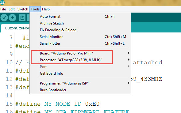
52 |
53 | **programming FTDI adapter connection**
54 |
55 | 
56 |
57 |
58 | 3.3V power option should be used.
59 |
60 |
61 | How to use it as home automation (IOT) node Relay
62 | ------------------------------------------------------
63 |
64 |
65 | wallSocketInsertableNode.ino is the Arduino example sketch using [MySensors](https://www.mysensors.org/) API.
66 |
67 | Burn the wallSocketInsertableNode.ino sketch into it and it will became one of the MySensors home automation network Relay Node. The Relay could be controlable from a smarthome controller web interface or smarphone App.
68 | To create Home Automation Network you need smarthome controller and at least two Nodes one as a Sensor, relay or actuator Node and the other one as “Gateway Serial” connected to the smarthome controller. I personally love [Domoticz](https://domoticz.com/) as smarthome conroller. Please check this [HowTo](https://github.com/EasySensors/ButtonSizeNode/blob/master/DomoticzInstallMySensors.md) to install Domoticz.
69 |
70 | However, for no-controller setup, as example, you can use 3 nodes - first node as “Gateway Serial”, second node as the Mini Relay Box node and the last one as switch for the relay node. No controller needed then, keep the switch and the relay node on the same address and the switch will operate the relay node.
71 |
72 | Things worth mentioning about the [MySensors](https://www.mysensors.org/) Arduino sketch:
73 |
74 |
75 | Code | Description
76 | ------------|--------------
77 | #define MY_RADIO_RFM69
#define MY_RFM69_FREQUENCY RF69_433MHZ
#define MY_IS_RFM69HW| Define which radio we use – here is RFM 69
with frequency 433 MHZ and it is HW
type – one of the most powerful RFM 69 radios.
If your radio is RFM69CW - comment out line
with // #define MY_IS_RFM69HW
78 | #define MY_NODE_ID 0xE0 | Define Node address (0xE0 here). I prefer to use static addresses
and in Hexadecimal since it is easier to identify the node
address in [Domoticz](https://domoticz.com/) devices list after it
will be discovered by controller ( [Domoticz](https://domoticz.com/)).
However, you can use AUTO instead of the hardcoded number
(like 0xE0) though. [Domoticz](https://domoticz.com/) will automatically assign node ID then.
79 | #define MY_OTA_FIRMWARE_FEATURE
#define MY_OTA_FLASH_JDECID 0x0 | Define OTA feature. OTA stands for “Over The Air firmware updates”.
If your node does not utilize Sleep mode you can send new “firmware”
(compiled sketch binary) by air. **Here is the link on how to do it.**
For OTA we use JDEC Flash chip where the node stores
new firmware and once it received and controlsum (CRC) is correct
it reboots and flashes your new code into the node
controller. So we define it is "erase type" as 0x2020 here.
80 | #define MY_SIGNING_ATSHA204
#define MY_SIGNING_REQUEST_SIGNATURES | Define if you like to use Crypto Authentication to secure your nodes
from intruders or interference. After that, you have to “personalize”
all the nodes, which have those, defines enabled.
[**How to “personalize” nodes with encryption key**](https://github.com/EasySensors/ButtonSizeNode/blob/master/SecurityPersonalizationHowTo.md).
You need both defines in the nodes you need to protect.
The Gateway Serial could be with only one of those
defines enabled - #define MY_SIGNING_ATSHA204
81 | #define AdafruitNeoPixel | Enables onboard Pixel LED SK6812mini
82 |
83 | Connect the Relay to FTDI USB adaptor, Select Pro Mini 8MHz board and burn the wallSocketInsertableNode.ino sketch.
84 |
85 | **Done**
86 |
87 |
88 | The board is created by [Koresh](https://www.openhardware.io/user/143/projects/Koresh)
89 |
90 | 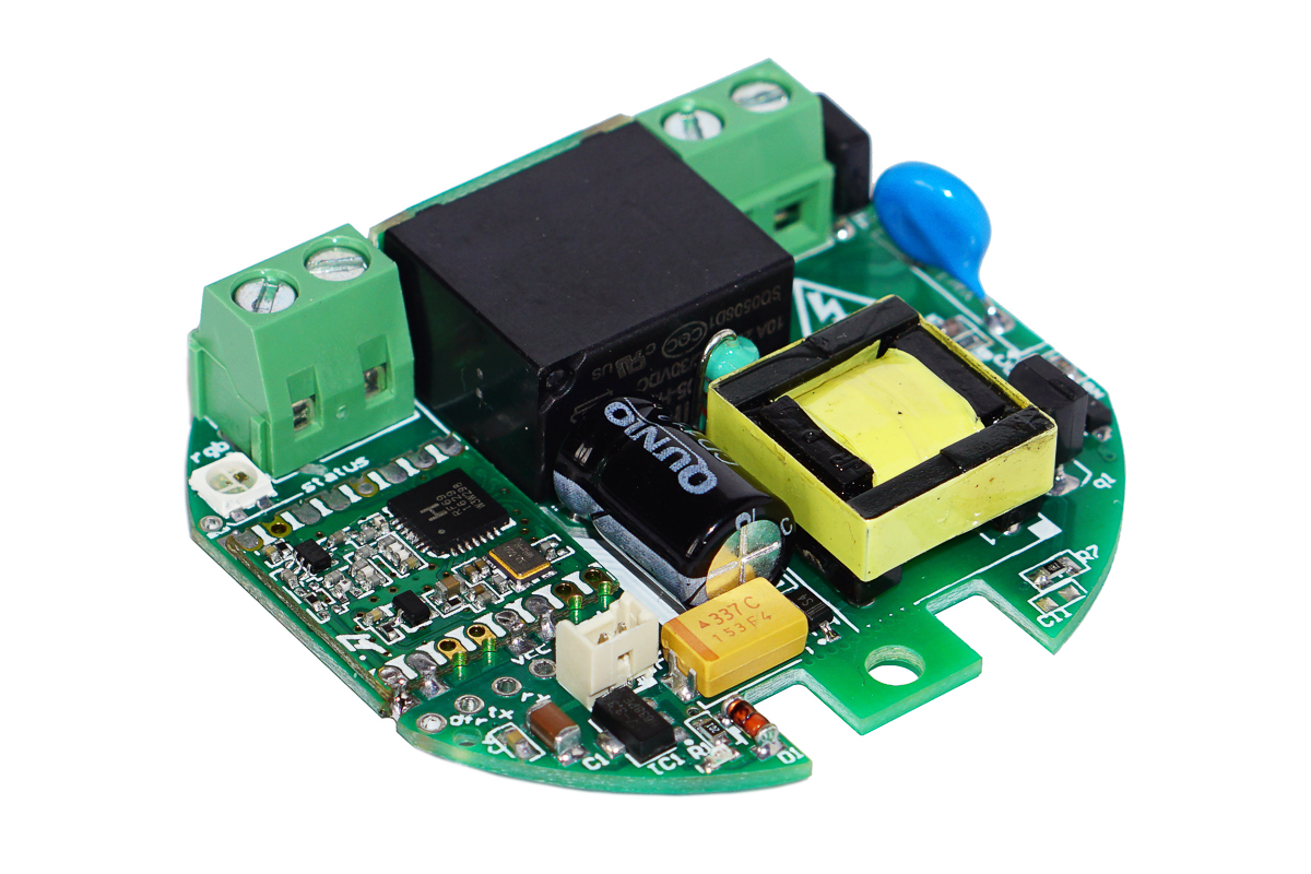 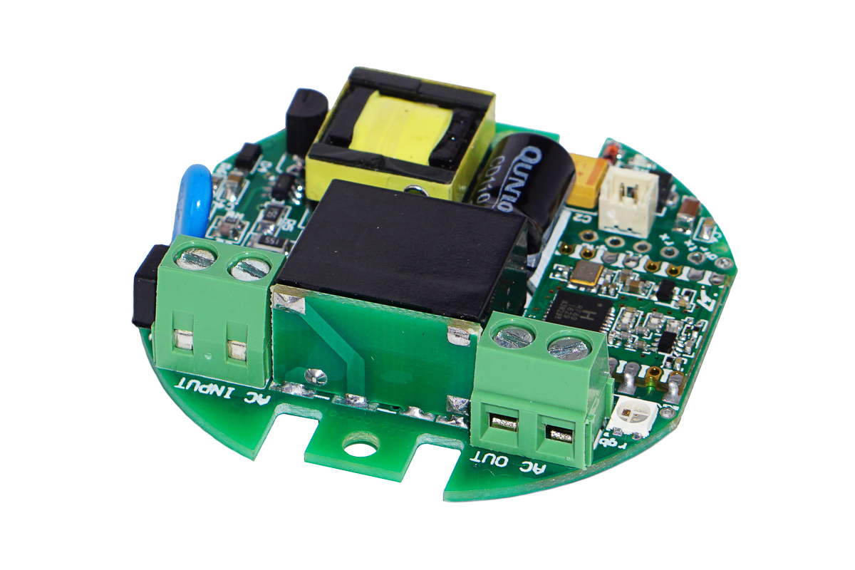 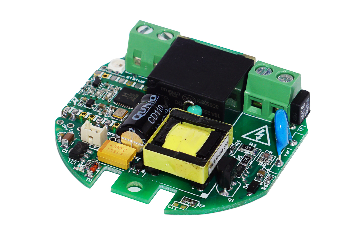
91 | 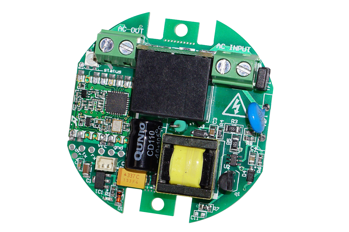
92 |
93 | >[The board schematics Pdf link](https://github.com/EasySensors/WallSocketInsertableNode/blob/master/pdf/WallInsertableSocket_sch.pdf)
94 |
--------------------------------------------------------------------------------
/WallSocketInsertableNode.ino:
--------------------------------------------------------------------------------
1 | /**
2 | * The MySensors Arduino library handles the wireless radio link and protocol
3 | * between your home built sensors/actuators and HA controller of choice.
4 | * The sensors forms a self healing radio network with optional repeaters. Each
5 | * repeater and gateway builds a routing tables in EEPROM which keeps track of the
6 | * network topology allowing messages to be routed to nodes.
7 | *
8 | * Created by Henrik Ekblad
9 | * Copyright (C) 2013-2015 Sensnology AB
10 | * Full contributor list: https://github.com/mysensors/Arduino/graphs/contributors
11 | *
12 | * Documentation: http://www.mysensors.org
13 | * Support Forum: http://forum.mysensors.org
14 | *
15 | * This program is free software; you can redistribute it and/or
16 | * modify it under the terms of the GNU General Public License
17 | * version 2 as published by the Free Software Foundation.
18 | *
19 | **/
20 |
21 |
22 |
23 | // Enable debug prints to serial monitor
24 | #define MY_DEBUG
25 |
26 | // Enable onbaord Pixel LED SK6812mini
27 | #define AdafruitNeoPixel
28 |
29 | // Comment it out for Auto Node ID #
30 | #define MY_NODE_ID 0xC2
31 |
32 | // Enable and select radio type attached
33 | #define MY_RADIO_RFM69
34 | //#define MY_RFM69_NEW_DRIVER
35 |
36 | // MySensors 2.0
37 | #define MY_RFM69_FREQUENCY RF69_433MHZ
38 | //#define MY_RFM69_FREQUENCY RF69_868MHZ
39 | //#define MY_RFM69_FREQUENCY RF69_915MHZ
40 |
41 |
42 | // MySensors 2.2 and up style
43 | //#define MY_RFM69_FREQUENCY RFM69_868MHZ
44 | //#define MY_RFM69_FREQUENCY RFM69_433MHZ
45 | //#define MY_RFM69_FREQUENCY RFM69_915MHZ
46 |
47 | #define MY_IS_RFM69HW
48 |
49 | //Enable OTA feature
50 | #define MY_OTA_FIRMWARE_FEATURE
51 | #define MY_OTA_FLASH_JDECID 0 //0x2020
52 |
53 | //Enable Crypto Authentication to secure the node
54 | //#define MY_SIGNING_ATSHA204
55 | //#define MY_SIGNING_REQUEST_SIGNATURES
56 |
57 | // Type of switch connected to the white JST connector on the board. A2 arduino Pin
58 | // Momentary is notebook\laptop keyboard style key.
59 | #define MOMENTARY_SWITCH
60 |
61 | #ifdef AdafruitNeoPixel
62 | #include
63 | // Which pin on the Arduino is connected to the NeoPixels?
64 | #define PIN 6
65 | // How many NeoPixels are attached to the Arduino?
66 | #define NUMPIXELS 1
67 | #define NEO_PTYPE NEO_GRB 1
68 | Adafruit_NeoPixel pixels = Adafruit_NeoPixel(NUMPIXELS, PIN, NEO_GRB + NEO_KHZ800);
69 | #endif
70 |
71 | #include
72 | #ifdef __AVR__
73 | #include
74 | #endif
75 |
76 | #include
77 | #include
78 |
79 | //--------------------- https://github.com/JonHub/Filters
80 | #include
81 | float testFrequency = 50; // test signal frequency (Hz)
82 | float windowLength = 20.0/testFrequency; // how long to average the signal, for statistist
83 |
84 | #define RELAY_pin 7 // Digital pin connected to relay
85 |
86 | #define RELAY_sensor 1
87 | #define Current_sensor 2
88 | #define TEMP_sensor 3
89 |
90 | #define RELAY_ON 1 // GPIO value to write to turn on attached relay
91 | #define RELAY_OFF 0 // GPIO value to write to turn off attached relay
92 |
93 | //#define SPIFLASH_BLOCKERASE_32K 0x52
94 | #define SPIFLASH_BLOCKERASE_32K 0xD8 // Redefine erase block and CHIPERASE commands here. so please keep these two lines AFTER #include
95 | #define SPIFLASH_CHIPERASE 0x60
96 |
97 | MyMessage msg(RELAY_sensor, V_LIGHT);
98 | MyMessage msg_current(Current_sensor, V_CURRENT);
99 | MyMessage msg_temp(TEMP_sensor, V_TEMP);
100 |
101 | RunningStatistics inputStats; // create statistics to look at the raw test signal
102 |
103 | static uint8_t value_ext_sw = HIGH, last_value_ext_sw = HIGH;
104 | static uint8_t temp_rfmPrevoiusReadings = 0;
105 | static float ACS712AmpsPrevoiusReadings = 0;
106 |
107 | #include
108 | Bounce debouncer = Bounce();
109 |
110 | void reportCurrent()
111 | {
112 | float ACS712amps;
113 | char amps_txt[10];
114 | char temp_txt[10];
115 | // The temperature reading is depricated in New RFM 69 driver
116 | int temp_rfm = (int)_radio.readTemperature(0);
117 |
118 | //It is linear regression for amperes against onboard ACS712 sigma eadings
119 | ACS712amps = 0.05856*inputStats.sigma() - 0.2126;
120 | //convert it to a string
121 | dtostrf(ACS712amps,0,2,amps_txt);
122 |
123 | if (abs( (ACS712amps - ACS712AmpsPrevoiusReadings)) > 0.1 && ACS712amps > 0){
124 | ACS712AmpsPrevoiusReadings = ACS712amps;
125 | wait(100);
126 | send(msg_current.set(amps_txt), true); // Send new state and request ack back
127 | }
128 |
129 | if (abs(temp_rfmPrevoiusReadings - temp_rfm)>= 3){
130 | temp_rfmPrevoiusReadings = temp_rfm;
131 | Serial.print( "\tRFM temp: " ); Serial.println( temp_rfm );
132 | wait(100);
133 | send(msg_temp.set(temp_rfm), true); // Send RFM module temp sensor readings
134 | }
135 | }
136 |
137 | void before() {
138 | // watchdog sets to 8 secs
139 | wdt_enable(WDTO_8S); //wdt_disable();
140 | // in case watchdog resets node - we do RFM69 reset here since VDD (power) is not disconnected while watchdog resets the node. Just in case!
141 | /* RFM reset pin is 9
142 | * A manual reset of the RFM69HCW\CW is possible even for applications in which VDD cannot be physically disconnected.
143 | * Pin RESET should be pulled high for a hundred microseconds, and then released. The user should then wait for 5 ms
144 | * before using the module.
145 | */
146 | pinMode(9, OUTPUT);
147 | //reset RFM module
148 | digitalWrite(9, 1);
149 | delay(1);
150 | // set Pin 9 to high impedance
151 | pinMode(9, INPUT);
152 | delay(10);
153 |
154 | // External button with JST connector
155 | pinMode(A2, INPUT_PULLUP);
156 | digitalWrite(A2,HIGH);
157 |
158 | // Debouncing the button
159 | debouncer.attach(A2);
160 | debouncer.interval(20);
161 |
162 | #ifdef AdafruitNeoPixel
163 | pixels.begin();
164 | pixels.setPixelColor(0,pixels.Color(0,0,255)); // R G B
165 | pixels.setBrightness(50); //0-255
166 | pixels.show();
167 | #endif
168 |
169 | // Call void amps() to update current and temperature readings.
170 | inputStats.setWindowSecs( windowLength );
171 | // Then set relay pins in output mode
172 | pinMode(RELAY_pin, OUTPUT);
173 | // Set relay to last known state (using eeprom storage)
174 | digitalWrite(RELAY_pin, loadState(RELAY_sensor)?RELAY_ON:RELAY_OFF);
175 |
176 | #ifdef AdafruitNeoPixel
177 | pixels.setPixelColor(0,loadState(RELAY_sensor)?pixels.Color(255,0,0):pixels.Color(0,255,0));
178 | pixels.show();
179 | #endif
180 | //_radio.readAllRegs();
181 | }
182 |
183 | void setup() {
184 |
185 | }
186 |
187 | void presentation()
188 | {
189 | // Send the sketch version information to the gateway and Controller
190 | sendSketchInfo("Insertable Relay node","2.0");
191 |
192 | // Register all sensors to gw (they will be created as child devices)
193 | present(RELAY_sensor, S_LIGHT);
194 | present(Current_sensor, S_MULTIMETER);
195 | present(TEMP_sensor, S_TEMP); // RFM 69 Radio have temp sensor. keep this if you like temp reported to a controller
196 | }
197 |
198 | void loop()
199 | {
200 | boolean loadedState;
201 | wdt_reset();
202 | //Serial.print("RSSI "); Serial.println(_radio.readRSSI());
203 |
204 | #ifdef MOMENTARY_SWITCH
205 | // read and debounced digitalRead(A2);
206 | debouncer.update();
207 | value_ext_sw = debouncer.read();
208 | if (value_ext_sw == 0 && last_value_ext_sw == 1){
209 | loadedState = loadState(RELAY_sensor) == 1? true:false;
210 | // Change relay state
211 | digitalWrite(RELAY_pin, !loadedState?RELAY_ON:RELAY_OFF);
212 |
213 | #ifdef AdafruitNeoPixel
214 | pixels.setPixelColor(0,!loadedState ?pixels.Color(255,0,0):pixels.Color(0,255,0));
215 | pixels.show();
216 | wait(100);
217 | #endif
218 |
219 | // Store state into eeprom
220 | saveState(RELAY_sensor, !loadedState?RELAY_ON:RELAY_OFF);
221 | // update controller with new relays state
222 | msg.setDestination(0);
223 | send(msg.set(!loadedState?RELAY_ON:RELAY_OFF), true);
224 | last_value_ext_sw = value_ext_sw;
225 | }
226 | else {
227 | last_value_ext_sw = value_ext_sw;
228 | }
229 |
230 | #else
231 | // read and debounce digitalRead(A2);
232 | debouncer.update();
233 | value_ext_sw = debouncer.read();
234 | if (last_value_ext_sw != value_ext_sw){
235 | last_value_ext_sw = value_ext_sw;
236 | //Serial.println("VALUE"); Serial.println(value_ext_sw);
237 | // Change relay state
238 | digitalWrite(RELAY_pin, value_ext_sw?RELAY_ON:RELAY_OFF);
239 |
240 | #ifdef AdafruitNeoPixel
241 | pixels.setPixelColor(0,!loadedState ?pixels.Color(255,0,0):pixels.Color(0,255,0));
242 | pixels.show();
243 | wait(100);
244 | #endif
245 |
246 | // Store state into eeprom
247 | saveState(RELAY_sensor, value_ext_sw?RELAY_ON:RELAY_OFF);
248 | msg.setDestination(0);
249 | send(msg.set(value_ext_sw?RELAY_ON:RELAY_OFF), true);
250 | }
251 | #endif
252 | inputStats.input(analogRead(A1)); // log to Stats function for ampers from A1 analog input
253 | static unsigned long lastCurrentSensorMillis = 0, currentSensorInterval = 5000;
254 | // Check if we reach the max millis of 4,294,967,295
255 | millis() < lastCurrentSensorMillis ? lastCurrentSensorMillis = 0:0;
256 | if (millis() > (lastCurrentSensorMillis + currentSensorInterval)){
257 | lastCurrentSensorMillis = millis();
258 | reportCurrent();
259 | }
260 | }
261 |
262 | void receive(const MyMessage &message) {
263 | // We only expect one type of message from controller. But we better check anyway.
264 | if (message.type==V_LIGHT) {
265 | // Change relay state
266 | digitalWrite(RELAY_pin, message.getBool()?RELAY_ON:RELAY_OFF);
267 | // Store state in eeprom
268 | saveState(message.sensor, message.getBool()?RELAY_ON:RELAY_OFF);
269 | #ifdef AdafruitNeoPixel
270 | wait(100);
271 | // Blink blue light to see radio communication with the gateway is
272 | pixels.setPixelColor(0,pixels.Color(0,0,255));
273 | pixels.show();
274 | wait(100);
275 | // Set Red for ON and green fo OFF
276 | pixels.setPixelColor(0,message.getBool() ?pixels.Color(255,0,0):pixels.Color(0,255,0));
277 | pixels.show();
278 | #endif
279 | Serial.print("Incoming change for sensor:");
280 | Serial.print(message.sensor);
281 | Serial.print(", New status: ");
282 | Serial.println(message.getBool());
283 | }
284 | }
285 |
--------------------------------------------------------------------------------
/pdf/EbayPageReadme.md:
--------------------------------------------------------------------------------
1 | ### Wall Socket Insertable Node is extremely low profile wireless 220 Volts 10A Relay board. It switches on-off 220 Volts on its output terminals. It is suitable for installing into wall socket compartment in between the socket and the wall. The board height is only 13mm. Comes without plastic enclosure. Arduino IDE compatible (the Atmel ATMega328P) microcontroller with RFM 69 HW 433 MHz radio on board and current sensor. Best suitable for Home Automation, IOT.
2 |
3 |
4 | ## Features
5 | - Fully compatible with the Arduino IDE (PRO MINI 8 MG Hz)
6 | - Board Dimensions: Diameter is 55mm and Height is only 13mm
7 | - Uncompromised protection:
8 | Overload varistor
9 | Slow fuse
10 | Thermal fuse
11 | - It is 220 V version: Supply voltage 160-240 Volts AC
12 | - Over the Air, firmware updates (OTA) ready. In combination with preprogrammed dual optiboot boot loader and external JDEC EPROM\Flash memory chip on board the node allows OTA software updates.
13 | - Onboard RFM69-HW (high power version) 433 MHz radio transceiver with wire antenna
14 | - Onboard Atmel ATSHA204A CryptoAuthentication chip makes communication with the node very secured. ATSHA204A implements secured handshake and if handshake fails the node will not executing any command sent to it
15 | - Programming header is FTDI, TTL Serial. For programming, you need to have USB TTL Serial – FTDI adaptor
16 | - MySensors compatible. You can use superb set of scripts and libraries from [mysensors.org](http://www.mysensors.org) project and convert the node into reliable network of little home sensors, relays and actuators.
17 | - Yes, it is open sourced. Completely
18 |
19 | Comes with Arduino example sketch and guide to IOT, Smart home ideas.
20 |
21 | ## Overview
22 | If you are familiar with Arduino boards, the MiniRelayBox node is Arduino pro Mini with onboard HopeRF RFM69-HW 433 MHz radio, external EPROM flash and crypto authentication chip. Comes with 10A relay and current sensor. To save some board dimensions the MiniRelayBox node does not have onboard USB-Serial converter. You need to buy FTDI Adapter for programming. HopeRF RFM69-HW provide extremely good range. hundreds of meters in open area. External Flash chip allows burning Arduino sketch wirelessly. Onboard Atmel ATSHA204A CryptoAuthentication chip secures communication with other controllers. Some IOT ideas based on the Insertable Node and similar controllers plus complete specs you may find here [my GitHub page](https://github.com/EasySensors/WallSocketInsertableNode)
23 |
24 | 
25 | 
26 | 
27 | 
28 | 
29 | 
30 | 
31 |
32 |
33 | Package Content:
34 | - The Wall Socket Insertable board 1 pcs
35 | - JST wire connector male 1 pcs
36 |
--------------------------------------------------------------------------------
/pdf/WallInsertableSocket_sch.pdf:
--------------------------------------------------------------------------------
https://raw.githubusercontent.com/EasySensors/WallSocketInsertableNode/55e5eb3543cac139120cd63a2abaa16b194ea39d/pdf/WallInsertableSocket_sch.pdf
--------------------------------------------------------------------------------
/pics/Antn.jpg:
--------------------------------------------------------------------------------
https://raw.githubusercontent.com/EasySensors/WallSocketInsertableNode/55e5eb3543cac139120cd63a2abaa16b194ea39d/pics/Antn.jpg
--------------------------------------------------------------------------------
/pics/Button.jpg:
--------------------------------------------------------------------------------
https://raw.githubusercontent.com/EasySensors/WallSocketInsertableNode/55e5eb3543cac139120cd63a2abaa16b194ea39d/pics/Button.jpg
--------------------------------------------------------------------------------
/pics/FTDIvcc3.jpg:
--------------------------------------------------------------------------------
https://raw.githubusercontent.com/EasySensors/WallSocketInsertableNode/55e5eb3543cac139120cd63a2abaa16b194ea39d/pics/FTDIvcc3.jpg
--------------------------------------------------------------------------------
/pics/LEDregular - Copy.jpg:
--------------------------------------------------------------------------------
https://raw.githubusercontent.com/EasySensors/WallSocketInsertableNode/55e5eb3543cac139120cd63a2abaa16b194ea39d/pics/LEDregular - Copy.jpg
--------------------------------------------------------------------------------
/pics/LEDregular.jpg:
--------------------------------------------------------------------------------
https://raw.githubusercontent.com/EasySensors/WallSocketInsertableNode/55e5eb3543cac139120cd63a2abaa16b194ea39d/pics/LEDregular.jpg
--------------------------------------------------------------------------------
/pics/LEDregularTop.jpg:
--------------------------------------------------------------------------------
https://raw.githubusercontent.com/EasySensors/WallSocketInsertableNode/55e5eb3543cac139120cd63a2abaa16b194ea39d/pics/LEDregularTop.jpg
--------------------------------------------------------------------------------
/pics/Pins - Copy.jpg:
--------------------------------------------------------------------------------
https://raw.githubusercontent.com/EasySensors/WallSocketInsertableNode/55e5eb3543cac139120cd63a2abaa16b194ea39d/pics/Pins - Copy.jpg
--------------------------------------------------------------------------------
/pics/PinsShrt.jpg:
--------------------------------------------------------------------------------
https://raw.githubusercontent.com/EasySensors/WallSocketInsertableNode/55e5eb3543cac139120cd63a2abaa16b194ea39d/pics/PinsShrt.jpg
--------------------------------------------------------------------------------
/pics/WallSocketInsertableNode1.jpg:
--------------------------------------------------------------------------------
https://raw.githubusercontent.com/EasySensors/WallSocketInsertableNode/55e5eb3543cac139120cd63a2abaa16b194ea39d/pics/WallSocketInsertableNode1.jpg
--------------------------------------------------------------------------------
/pics/WallSocketInsertableNode11.jpg:
--------------------------------------------------------------------------------
https://raw.githubusercontent.com/EasySensors/WallSocketInsertableNode/55e5eb3543cac139120cd63a2abaa16b194ea39d/pics/WallSocketInsertableNode11.jpg
--------------------------------------------------------------------------------
/pics/WallSocketInsertableNode12.jpg:
--------------------------------------------------------------------------------
https://raw.githubusercontent.com/EasySensors/WallSocketInsertableNode/55e5eb3543cac139120cd63a2abaa16b194ea39d/pics/WallSocketInsertableNode12.jpg
--------------------------------------------------------------------------------
/pics/WallSocketInsertableNode13.jpg:
--------------------------------------------------------------------------------
https://raw.githubusercontent.com/EasySensors/WallSocketInsertableNode/55e5eb3543cac139120cd63a2abaa16b194ea39d/pics/WallSocketInsertableNode13.jpg
--------------------------------------------------------------------------------
/pics/WallSocketInsertableNode2.jpg:
--------------------------------------------------------------------------------
https://raw.githubusercontent.com/EasySensors/WallSocketInsertableNode/55e5eb3543cac139120cd63a2abaa16b194ea39d/pics/WallSocketInsertableNode2.jpg
--------------------------------------------------------------------------------
/pics/WallSocketInsertableNode3.jpg:
--------------------------------------------------------------------------------
https://raw.githubusercontent.com/EasySensors/WallSocketInsertableNode/55e5eb3543cac139120cd63a2abaa16b194ea39d/pics/WallSocketInsertableNode3.jpg
--------------------------------------------------------------------------------
/pics/WallSocketInsertableNode5.jpg:
--------------------------------------------------------------------------------
https://raw.githubusercontent.com/EasySensors/WallSocketInsertableNode/55e5eb3543cac139120cd63a2abaa16b194ea39d/pics/WallSocketInsertableNode5.jpg
--------------------------------------------------------------------------------
/pics/fssort.ini:
--------------------------------------------------------------------------------
1 | Antn.jpg
2 | Button.jpg
3 | LEDregular - Copy.jpg
4 | LEDregular.jpg
5 | LEDregularTop.jpg
6 | Pins - Copy.jpg
7 | PinsShrt.jpg
8 | replacee.jpg
9 | socket_25_03_bottom.png
10 | socket_25_03_top.png
11 | s1.jpg
12 | s2.jpg
13 | s3.jpg
14 | s5.jpg
15 | WallSocketInsertableNode2.jpg
16 | WallSocketInsertableNode3.jpg
17 | WallSocketInsertableNode5.jpg
18 | WallSocketInsertableNode1.jpg
19 | WallSocketInsertableNode11.jpg
20 | WallSocketInsertableNode12.jpg
21 | WallSocketInsertableNode13.jpg
22 | FTDIvcc3.jpg
23 |
--------------------------------------------------------------------------------
/pics/replacee.jpg:
--------------------------------------------------------------------------------
https://raw.githubusercontent.com/EasySensors/WallSocketInsertableNode/55e5eb3543cac139120cd63a2abaa16b194ea39d/pics/replacee.jpg
--------------------------------------------------------------------------------
/pics/s1.jpg:
--------------------------------------------------------------------------------
https://raw.githubusercontent.com/EasySensors/WallSocketInsertableNode/55e5eb3543cac139120cd63a2abaa16b194ea39d/pics/s1.jpg
--------------------------------------------------------------------------------
/pics/s2.jpg:
--------------------------------------------------------------------------------
https://raw.githubusercontent.com/EasySensors/WallSocketInsertableNode/55e5eb3543cac139120cd63a2abaa16b194ea39d/pics/s2.jpg
--------------------------------------------------------------------------------
/pics/s3.jpg:
--------------------------------------------------------------------------------
https://raw.githubusercontent.com/EasySensors/WallSocketInsertableNode/55e5eb3543cac139120cd63a2abaa16b194ea39d/pics/s3.jpg
--------------------------------------------------------------------------------
/pics/s5.jpg:
--------------------------------------------------------------------------------
https://raw.githubusercontent.com/EasySensors/WallSocketInsertableNode/55e5eb3543cac139120cd63a2abaa16b194ea39d/pics/s5.jpg
--------------------------------------------------------------------------------
/pics/socket_25_03_bottom.png:
--------------------------------------------------------------------------------
https://raw.githubusercontent.com/EasySensors/WallSocketInsertableNode/55e5eb3543cac139120cd63a2abaa16b194ea39d/pics/socket_25_03_bottom.png
--------------------------------------------------------------------------------
/pics/socket_25_03_top.png:
--------------------------------------------------------------------------------
https://raw.githubusercontent.com/EasySensors/WallSocketInsertableNode/55e5eb3543cac139120cd63a2abaa16b194ea39d/pics/socket_25_03_top.png
--------------------------------------------------------------------------------