├── .github
└── FUNDING.yml
├── LICENSE.md
├── MGBC PCB
├── MGBC-MBL-01_2-0S.brd
├── MGBC-MBL-01_2-0S.sch
├── MGBC-MBL-01_2-0S_GERBERS.zip
├── MGBC-MBL-01_2_1.brd
├── MGBC-MBL-01_2_1.sch
├── MGBC-MBL-01_2_1_GERBERS.zip
└── README.md
├── MGBC_BOM.csv
├── MGBC_BOM.xlsx
├── README.md
├── Technical
├── README.md
├── schematic.png
├── schematic_v1-5_(OLD).png
└── schematic_v1-6_(OLD).png
├── audio_GBC.mp3
├── audio_MGBC.mp3
└── previous_revs_BOM.csv
/.github/FUNDING.yml:
--------------------------------------------------------------------------------
1 | # These are supported funding model platforms
2 |
3 | github: # Replace with up to 4 GitHub Sponsors-enabled usernames e.g., [user1, user2]
4 | patreon: # Replace with a single Patreon username
5 | open_collective: # Replace with a single Open Collective username
6 | ko_fi: bucketmouse
7 | tidelift: # Replace with a single Tidelift platform-name/package-name e.g., npm/babel
8 | community_bridge: # Replace with a single Community Bridge project-name e.g., cloud-foundry
9 | liberapay: # Replace with a single Liberapay username
10 | issuehunt: # Replace with a single IssueHunt username
11 | otechie: # Replace with a single Otechie username
12 | lfx_crowdfunding: # Replace with a single LFX Crowdfunding project-name e.g., cloud-foundry
13 | custom: # Replace with up to 4 custom sponsorship URLs e.g., ['link1', 'link2']
14 |
--------------------------------------------------------------------------------
/LICENSE.md:
--------------------------------------------------------------------------------
1 | Creative Commons Attribution-ShareAlike 4.0 International
2 |
3 | Creative Commons Corporation ("Creative Commons") is not a law firm and
4 | does not provide legal services or legal advice. Distribution of
5 | Creative Commons public licenses does not create a lawyer-client or
6 | other relationship. Creative Commons makes its licenses and related
7 | information available on an "as-is" basis. Creative Commons gives no
8 | warranties regarding its licenses, any material licensed under their
9 | terms and conditions, or any related information. Creative Commons
10 | disclaims all liability for damages resulting from their use to the
11 | fullest extent possible.
12 |
13 | Using Creative Commons Public Licenses
14 |
15 | Creative Commons public licenses provide a standard set of terms and
16 | conditions that creators and other rights holders may use to share
17 | original works of authorship and other material subject to copyright and
18 | certain other rights specified in the public license below. The
19 | following considerations are for informational purposes only, are not
20 | exhaustive, and do not form part of our licenses.
21 |
22 | Considerations for licensors: Our public licenses are intended for use
23 | by those authorized to give the public permission to use material in
24 | ways otherwise restricted by copyright and certain other rights. Our
25 | licenses are irrevocable. Licensors should read and understand the terms
26 | and conditions of the license they choose before applying it. Licensors
27 | should also secure all rights necessary before applying our licenses so
28 | that the public can reuse the material as expected. Licensors should
29 | clearly mark any material not subject to the license. This includes
30 | other CC-licensed material, or material used under an exception or
31 | limitation to copyright. More considerations for licensors :
32 | wiki.creativecommons.org/Considerations_for_licensors
33 |
34 | Considerations for the public: By using one of our public licenses, a
35 | licensor grants the public permission to use the licensed material under
36 | specified terms and conditions. If the licensor's permission is not
37 | necessary for any reason–for example, because of any applicable
38 | exception or limitation to copyright–then that use is not regulated by
39 | the license. Our licenses grant only permissions under copyright and
40 | certain other rights that a licensor has authority to grant. Use of the
41 | licensed material may still be restricted for other reasons, including
42 | because others have copyright or other rights in the material. A
43 | licensor may make special requests, such as asking that all changes be
44 | marked or described.
45 |
46 | Although not required by our licenses, you are encouraged to respect
47 | those requests where reasonable. More considerations for the public :
48 | wiki.creativecommons.org/Considerations_for_licensees
49 |
50 | Creative Commons Attribution-ShareAlike 4.0 International Public License
51 |
52 | By exercising the Licensed Rights (defined below), You accept and agree
53 | to be bound by the terms and conditions of this Creative Commons
54 | Attribution-ShareAlike 4.0 International Public License ("Public
55 | License"). To the extent this Public License may be interpreted as a
56 | contract, You are granted the Licensed Rights in consideration of Your
57 | acceptance of these terms and conditions, and the Licensor grants You
58 | such rights in consideration of benefits the Licensor receives from
59 | making the Licensed Material available under these terms and conditions.
60 |
61 | Section 1 – Definitions.
62 |
63 | - a. Adapted Material means material subject to Copyright and Similar
64 | Rights that is derived from or based upon the Licensed Material and
65 | in which the Licensed Material is translated, altered, arranged,
66 | transformed, or otherwise modified in a manner requiring permission
67 | under the Copyright and Similar Rights held by the Licensor. For
68 | purposes of this Public License, where the Licensed Material is a
69 | musical work, performance, or sound recording, Adapted Material is
70 | always produced where the Licensed Material is synched in timed
71 | relation with a moving image.
72 | - b. Adapter's License means the license You apply to Your Copyright
73 | and Similar Rights in Your contributions to Adapted Material in
74 | accordance with the terms and conditions of this Public License.
75 | - c. BY-SA Compatible License means a license listed at
76 | creativecommons.org/compatiblelicenses, approved by Creative Commons
77 | as essentially the equivalent of this Public License.
78 | - d. Copyright and Similar Rights means copyright and/or similar
79 | rights closely related to copyright including, without limitation,
80 | performance, broadcast, sound recording, and Sui Generis Database
81 | Rights, without regard to how the rights are labeled or categorized.
82 | For purposes of this Public License, the rights specified in Section
83 | 2(b)(1)-(2) are not Copyright and Similar Rights.
84 | - e. Effective Technological Measures means those measures that, in
85 | the absence of proper authority, may not be circumvented under laws
86 | fulfilling obligations under Article 11 of the WIPO Copyright Treaty
87 | adopted on December 20, 1996, and/or similar international
88 | agreements.
89 | - f. Exceptions and Limitations means fair use, fair dealing, and/or
90 | any other exception or limitation to Copyright and Similar Rights
91 | that applies to Your use of the Licensed Material.
92 | - g. License Elements means the license attributes listed in the name
93 | of a Creative Commons Public License. The License Elements of this
94 | Public License are Attribution and ShareAlike.
95 | - h. Licensed Material means the artistic or literary work, database,
96 | or other material to which the Licensor applied this Public License.
97 | - i. Licensed Rights means the rights granted to You subject to the
98 | terms and conditions of this Public License, which are limited to
99 | all Copyright and Similar Rights that apply to Your use of the
100 | Licensed Material and that the Licensor has authority to license.
101 | - j. Licensor means the individual(s) or entity(ies) granting rights
102 | under this Public License.
103 | - k. Share means to provide material to the public by any means or
104 | process that requires permission under the Licensed Rights, such as
105 | reproduction, public display, public performance, distribution,
106 | dissemination, communication, or importation, and to make material
107 | available to the public including in ways that members of the public
108 | may access the material from a place and at a time individually
109 | chosen by them.
110 | - l. Sui Generis Database Rights means rights other than copyright
111 | resulting from Directive 96/9/EC of the European Parliament and of
112 | the Council of 11 March 1996 on the legal protection of databases,
113 | as amended and/or succeeded, as well as other essentially equivalent
114 | rights anywhere in the world.
115 | - m. You means the individual or entity exercising the Licensed Rights
116 | under this Public License. Your has a corresponding meaning.
117 |
118 | Section 2 – Scope.
119 |
120 | - a. License grant.
121 | - 1. Subject to the terms and conditions of this Public License,
122 | the Licensor hereby grants You a worldwide, royalty-free,
123 | non-sublicensable, non-exclusive, irrevocable license to
124 | exercise the Licensed Rights in the Licensed Material to:
125 | - A. reproduce and Share the Licensed Material, in whole or in
126 | part; and
127 | - B. produce, reproduce, and Share Adapted Material.
128 | - 2. Exceptions and Limitations. For the avoidance of doubt, where
129 | Exceptions and Limitations apply to Your use, this Public
130 | License does not apply, and You do not need to comply with its
131 | terms and conditions.
132 | - 3. Term. The term of this Public License is specified in Section
133 | 6(a).
134 | - 4. Media and formats; technical modifications allowed. The
135 | Licensor authorizes You to exercise the Licensed Rights in all
136 | media and formats whether now known or hereafter created, and to
137 | make technical modifications necessary to do so. The Licensor
138 | waives and/or agrees not to assert any right or authority to
139 | forbid You from making technical modifications necessary to
140 | exercise the Licensed Rights, including technical modifications
141 | necessary to circumvent Effective Technological Measures. For
142 | purposes of this Public License, simply making modifications
143 | authorized by this Section 2(a)(4) never produces Adapted
144 | Material.
145 | - 5. Downstream recipients.
146 | - A. Offer from the Licensor – Licensed Material. Every
147 | recipient of the Licensed Material automatically receives an
148 | offer from the Licensor to exercise the Licensed Rights
149 | under the terms and conditions of this Public License.
150 | - B. Additional offer from the Licensor – Adapted Material.
151 | Every recipient of Adapted Material from You automatically
152 | receives an offer from the Licensor to exercise the Licensed
153 | Rights in the Adapted Material under the conditions of the
154 | Adapter's License You apply.
155 | - C. No downstream restrictions. You may not offer or impose
156 | any additional or different terms or conditions on, or apply
157 | any Effective Technological Measures to, the Licensed
158 | Material if doing so restricts exercise of the Licensed
159 | Rights by any recipient of the Licensed Material.
160 | - 6. No endorsement. Nothing in this Public License constitutes or
161 | may be construed as permission to assert or imply that You are,
162 | or that Your use of the Licensed Material is, connected with, or
163 | sponsored, endorsed, or granted official status by, the Licensor
164 | or others designated to receive attribution as provided in
165 | Section 3(a)(1)(A)(i).
166 | - b. Other rights.
167 | - 1. Moral rights, such as the right of integrity, are not
168 | licensed under this Public License, nor are publicity, privacy,
169 | and/or other similar personality rights; however, to the extent
170 | possible, the Licensor waives and/or agrees not to assert any
171 | such rights held by the Licensor to the limited extent necessary
172 | to allow You to exercise the Licensed Rights, but not otherwise.
173 | - 2. Patent and trademark rights are not licensed under this
174 | Public License.
175 | - 3. To the extent possible, the Licensor waives any right to
176 | collect royalties from You for the exercise of the Licensed
177 | Rights, whether directly or through a collecting society under
178 | any voluntary or waivable statutory or compulsory licensing
179 | scheme. In all other cases the Licensor expressly reserves any
180 | right to collect such royalties.
181 |
182 | Section 3 – License Conditions.
183 |
184 | Your exercise of the Licensed Rights is expressly made subject to the
185 | following conditions.
186 |
187 | - a. Attribution.
188 | - 1. If You Share the Licensed Material (including in modified
189 | form), You must:
190 | - A. retain the following if it is supplied by the Licensor
191 | with the Licensed Material:
192 | - i. identification of the creator(s) of the Licensed
193 | Material and any others designated to receive
194 | attribution, in any reasonable manner requested by the
195 | Licensor (including by pseudonym if designated);
196 | - ii. a copyright notice;
197 | - iii. a notice that refers to this Public License;
198 | - iv. a notice that refers to the disclaimer of
199 | warranties;
200 |
201 | v. a URI or hyperlink to the Licensed Material to the
202 | extent reasonably practicable;
203 |
204 | - B. indicate if You modified the Licensed Material and retain
205 | an indication of any previous modifications; and
206 | - C. indicate the Licensed Material is licensed under this
207 | Public License, and include the text of, or the URI or
208 | hyperlink to, this Public License.
209 | - 2. You may satisfy the conditions in Section 3(a)(1) in any
210 | reasonable manner based on the medium, means, and context in
211 | which You Share the Licensed Material. For example, it may be
212 | reasonable to satisfy the conditions by providing a URI or
213 | hyperlink to a resource that includes the required information.
214 | - 3. If requested by the Licensor, You must remove any of the
215 | information required by Section 3(a)(1)(A) to the extent
216 | reasonably practicable.
217 | - b. ShareAlike.In addition to the conditions in Section 3(a), if You
218 | Share Adapted Material You produce, the following conditions also
219 | apply.
220 | - 1. The Adapter's License You apply must be a Creative Commons
221 | license with the same License Elements, this version or later,
222 | or a BY-SA Compatible License.
223 | - 2. You must include the text of, or the URI or hyperlink to, the
224 | Adapter's License You apply. You may satisfy this condition in
225 | any reasonable manner based on the medium, means, and context in
226 | which You Share Adapted Material.
227 | - 3. You may not offer or impose any additional or different terms
228 | or conditions on, or apply any Effective Technological Measures
229 | to, Adapted Material that restrict exercise of the rights
230 | granted under the Adapter's License You apply.
231 |
232 | Section 4 – Sui Generis Database Rights.
233 |
234 | Where the Licensed Rights include Sui Generis Database Rights that apply
235 | to Your use of the Licensed Material:
236 |
237 | - a. for the avoidance of doubt, Section 2(a)(1) grants You the right
238 | to extract, reuse, reproduce, and Share all or a substantial portion
239 | of the contents of the database;
240 | - b. if You include all or a substantial portion of the database
241 | contents in a database in which You have Sui Generis Database
242 | Rights, then the database in which You have Sui Generis Database
243 | Rights (but not its individual contents) is Adapted Material,
244 | including for purposes of Section 3(b); and
245 | - c. You must comply with the conditions in Section 3(a) if You Share
246 | all or a substantial portion of the contents of the database.
247 | For the avoidance of doubt, this Section 4 supplements and does not
248 | replace Your obligations under this Public License where the
249 | Licensed Rights include other Copyright and Similar Rights.
250 |
251 | Section 5 – Disclaimer of Warranties and Limitation of Liability.
252 |
253 | - a. Unless otherwise separately undertaken by the Licensor, to the
254 | extent possible, the Licensor offers the Licensed Material as-is and
255 | as-available, and makes no representations or warranties of any kind
256 | concerning the Licensed Material, whether express, implied,
257 | statutory, or other. This includes, without limitation, warranties
258 | of title, merchantability, fitness for a particular purpose,
259 | non-infringement, absence of latent or other defects, accuracy, or
260 | the presence or absence of errors, whether or not known or
261 | discoverable. Where disclaimers of warranties are not allowed in
262 | full or in part, this disclaimer may not apply to You.
263 | - b. To the extent possible, in no event will the Licensor be liable
264 | to You on any legal theory (including, without limitation,
265 | negligence) or otherwise for any direct, special, indirect,
266 | incidental, consequential, punitive, exemplary, or other losses,
267 | costs, expenses, or damages arising out of this Public License or
268 | use of the Licensed Material, even if the Licensor has been advised
269 | of the possibility of such losses, costs, expenses, or damages.
270 | Where a limitation of liability is not allowed in full or in part,
271 | this limitation may not apply to You.
272 | - c. The disclaimer of warranties and limitation of liability provided
273 | above shall be interpreted in a manner that, to the extent possible,
274 | most closely approximates an absolute disclaimer and waiver of all
275 | liability.
276 |
277 | Section 6 – Term and Termination.
278 |
279 | - a. This Public License applies for the term of the Copyright and
280 | Similar Rights licensed here. However, if You fail to comply with
281 | this Public License, then Your rights under this Public License
282 | terminate automatically.
283 | - b. Where Your right to use the Licensed Material has terminated
284 | under Section 6(a), it reinstates:
285 | - 1. automatically as of the date the violation is cured, provided
286 | it is cured within 30 days of Your discovery of the violation;
287 | or
288 | - 2. upon express reinstatement by the Licensor.
289 | - c. For the avoidance of doubt, this Section 6(b) does not affect any
290 | right the Licensor may have to seek remedies for Your violations of
291 | this Public License.
292 | - d. For the avoidance of doubt, the Licensor may also offer the
293 | Licensed Material under separate terms or conditions or stop
294 | distributing the Licensed Material at any time; however, doing so
295 | will not terminate this Public License.
296 | - e. Sections 1, 5, 6, 7, and 8 survive termination of this Public
297 | License.
298 |
299 | Section 7 – Other Terms and Conditions.
300 |
301 | - a. The Licensor shall not be bound by any additional or different
302 | terms or conditions communicated by You unless expressly agreed.
303 | - b. Any arrangements, understandings, or agreements regarding the
304 | Licensed Material not stated herein are separate from and
305 | independent of the terms and conditions of this Public License.
306 |
307 | Section 8 – Interpretation.
308 |
309 | - a. For the avoidance of doubt, this Public License does not, and
310 | shall not be interpreted to, reduce, limit, restrict, or impose
311 | conditions on any use of the Licensed Material that could lawfully
312 | be made without permission under this Public License.
313 | - b. To the extent possible, if any provision of this Public License
314 | is deemed unenforceable, it shall be automatically reformed to the
315 | minimum extent necessary to make it enforceable. If the provision
316 | cannot be reformed, it shall be severed from this Public License
317 | without affecting the enforceability of the remaining terms and
318 | conditions.
319 | - c. No term or condition of this Public License will be waived and no
320 | failure to comply consented to unless expressly agreed to by the
321 | Licensor.
322 | - d. Nothing in this Public License constitutes or may be interpreted
323 | as a limitation upon, or waiver of, any privileges and immunities
324 | that apply to the Licensor or You, including from the legal
325 | processes of any jurisdiction or authority.
326 |
327 | Creative Commons is not a party to its public licenses. Notwithstanding,
328 | Creative Commons may elect to apply one of its public licenses to
329 | material it publishes and in those instances will be considered the
330 | "Licensor." The text of the Creative Commons public licenses is
331 | dedicated to the public domain under the CC0 Public Domain Dedication.
332 | Except for the limited purpose of indicating that material is shared
333 | under a Creative Commons public license or as otherwise permitted by the
334 | Creative Commons policies published at creativecommons.org/policies,
335 | Creative Commons does not authorize the use of the trademark "Creative
336 | Commons" or any other trademark or logo of Creative Commons without its
337 | prior written consent including, without limitation, in connection with
338 | any unauthorized modifications to any of its public licenses or any
339 | other arrangements, understandings, or agreements concerning use of
340 | licensed material. For the avoidance of doubt, this paragraph does not
341 | form part of the public licenses.
342 |
343 | Creative Commons may be contacted at creativecommons.org.
344 |
--------------------------------------------------------------------------------
/MGBC PCB/MGBC-MBL-01_2-0S_GERBERS.zip:
--------------------------------------------------------------------------------
https://raw.githubusercontent.com/MouseBiteLabs/Game-Boy-Pocket-Color/e438e8a5643067cf37bb57570c9ef4bc98b809fd/MGBC PCB/MGBC-MBL-01_2-0S_GERBERS.zip
--------------------------------------------------------------------------------
/MGBC PCB/MGBC-MBL-01_2_1_GERBERS.zip:
--------------------------------------------------------------------------------
https://raw.githubusercontent.com/MouseBiteLabs/Game-Boy-Pocket-Color/e438e8a5643067cf37bb57570c9ef4bc98b809fd/MGBC PCB/MGBC-MBL-01_2_1_GERBERS.zip
--------------------------------------------------------------------------------
/MGBC PCB/README.md:
--------------------------------------------------------------------------------
1 | # MGBC-MBL-01
2 |
3 | Version 2.1:
4 | 
5 |
6 | Version 2.0S:
7 | 
8 |
9 | *Note: The v2.0 and v2.1 boards are nearly identical - the only difference is v2.1 has a notch cut in the bottom by the regulator.*
10 |
11 | This is the main circuit board in the MGBC build. This README will provide instructions for how to customize the build to your liking, as well as attempt to clear up any questions you may have about the build process.
12 |
13 | ## Board Characteristics and Order Information
14 |
15 | The zipped folder contains all the gerber files for this board, if you wish to order it from a board manufacturer yourself. Version 2.x refers to the PCB that is one solid color with little-to-no visible silkscreen on the front after assembly; Version 2.xS refers to the PCB that has the bottom half filled with slikscreen, to make it look like OEM Pocket boards.
16 |
17 | - Layers: 2
18 | - Thickness: 1 mm
19 | - Surface Finish: ENIG (or HASL, which is only acceptable if you are installing tactile buttons)
20 | - **NOTE: When ordering PCBs, add this note to the order: "The file milling.gbr contains outlines for plated slots. Please add plated slots on the PCB according to this layer."**
21 |
22 | **I sell this board on Etsy, so you don't have to buy multiples from board fabricators:**
23 |
24 |  25 |
26 | You can alternatively use the zipped folder at any board fabricator you like. You may also buy the board from PCBWay using these links (disclosure: I receive 10% of the sale value to go towards future PCB orders).
27 |
28 | **Solid color version:**
29 |
30 |
25 |
26 | You can alternatively use the zipped folder at any board fabricator you like. You may also buy the board from PCBWay using these links (disclosure: I receive 10% of the sale value to go towards future PCB orders).
27 |
28 | **Solid color version:**
29 |
30 |  31 |
32 | **Half-silkscreen version:**
33 |
34 |
35 |
36 | ## Customization Options
37 |
38 | This section will explain all of the different customization options available on this board while you assemble.
39 |
40 | ### Enabling Reset Button Functionality
41 |
42 | Bridge the pads labelled "RST" with solder to turn the navigation switch into a reset button whenever you push it in. It's not particularly easy to push the button in, so accidental resets shouldn't be a concern. But if you find yourself accidentally resetting the system, you can remove the solder from the pads to disable it.
43 |
44 | 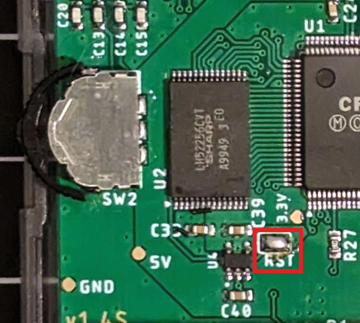
45 |
46 | ### Power LED Brightness
47 |
48 | Increase the value of R9 to decrease the brightness of the power LED during normal battery levels. Increase the value of R10 to decrease the brightness of the power LED during low battery levels. It is suggested to try changing resistances in ~10 kΩ increments.
49 |
50 | 
51 |
52 |
53 | ### Tactile Switches
54 |
55 | If you want clicky buttons, like the GBA SP has, then you can install tactile switches onto the button contacts. These are listed as B1-B8 on the BOM. There are three levels of clickiness to choose from, depending on the part number you select - SKRRAAE010 is the "least clicky" with 1 N operating force, SKRRABE010 has 1.6 N of operating force, and SKRRACE010 is the "most clicky" with 2 N of operating force. Note when installing the switches to make sure the little "wings" are oriented correctly as indicated on the board!
56 |
57 | 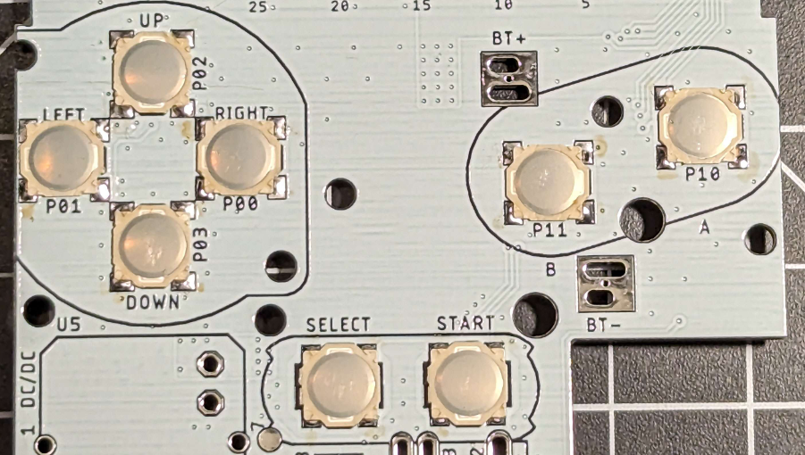
58 |
59 | ### Enabling the DC Jack (v2.0 and v2.1 only)
60 |
61 | When making the system for use with AAAs, you must connect the two holes labelled BT+ and DC together with a wire or 0 ohm resistor. This is only required on v2.0 and later boards - v1.6 and earlier do not require this. Shorting these holes together connects the DC jack to the input of the regulator. So if you forget to add it, then your DC jack won't work (which may or may not matter to you anyway). DO NOT SHORT THESE TOGETHER IF USING A LITHIUM-ION BATTERY.
62 |
63 | 
64 |
65 | ### LiPo Support
66 |
67 | Are you using the Game Boy Pocket Power regulator for U5 for LiPo support? Are you sure you want to? Lithium-ion batteries are **dangerous** so if you're going to be using one... you're on your own. You're responsible for using it safely.
68 |
69 | But, I did make it *slightly* easier for you. If you're using either my LiPo board or the GBPP with LiPo, solder wires or headers from the DC and BT+ holes into the power board, thread the wires from the battery through the hole in the board to the power board connections, and remember to **REMOVE EM7** if your board revision is v1.6 or earlier. On v2.0 and v2.1, keep EM7 in place. You'll also need a USB-C adapter PCB to go in place of DC jack.
70 |
71 | 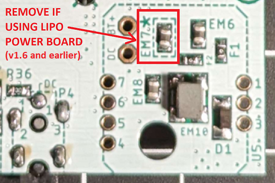
72 |
73 | Also, to get the power LED to dim at the correct time, remove R6 from the main MGBC board.
74 |
75 | 
76 |
77 | If you're using Nataliethenerd's Safer Charge DC, connect a wire from the "To F1" pad on the back of the board to the BT+ hole on the MGBC, and a wire from the "To 5V" pad on the back of the board to the pad on the USB-C breakout board. Then install the board into the U5 socket as normal.
78 |
79 | 
80 |
81 | ## Assembly References
82 |
83 | Here are a few images that should help clarify the build process, as well as provide some brief technical explanations to guide you in troubleshooting any errors you might have.
84 |
85 | ### Part Placement
86 |
87 | Some of the parts are a bit cramped, and it can be a bit difficult to decipher which part is which. Hopefully this image helps you clarify. (This is a photo from a previous version of the board, so the parts on your board may be slightly nudged from where they are in this image.)
88 |
89 | 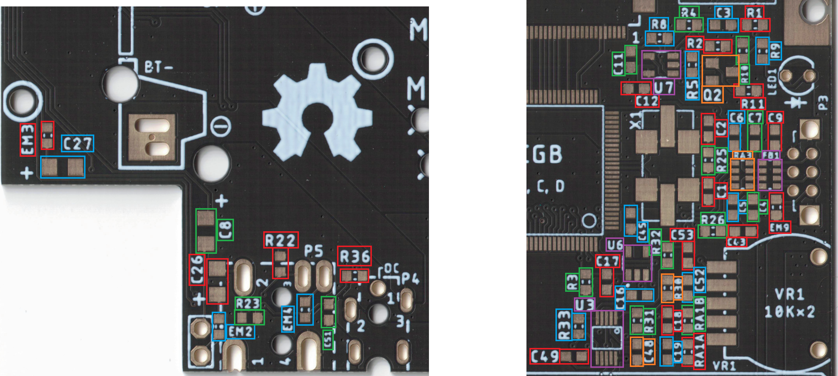
90 |
91 | ### CPU Pin Functions
92 |
93 | This is a bit of a mess, but depending on the problem you're encountering, it could be worth reflowing the pins on the CPU that correspond to the aspect you're having problems with.
94 | - For miscolored screens, reflow the top display pins.
95 | - For *glitchy* screens, or frozen/all-white screens, reflow the SRAM pins.
96 | - If you're missing button inputs, reflow the bottom left corner button pins.
97 | - If you have games that don't start up properly and hang at the Nintendo logo during start-up, display a glitchy Nintendo logo, or randomly freeze during gameplay, reflow the cartridge pins and clean your cartridge connector. The freezing may also be caused by poorly connected SRAM as well.
98 | - Three link port pins are on the bottom right, but there is one lone one at the top.
99 | - In general, reflowing the clock and power pins (colored red, pink, and black) can solve problems as well.
100 |
101 | 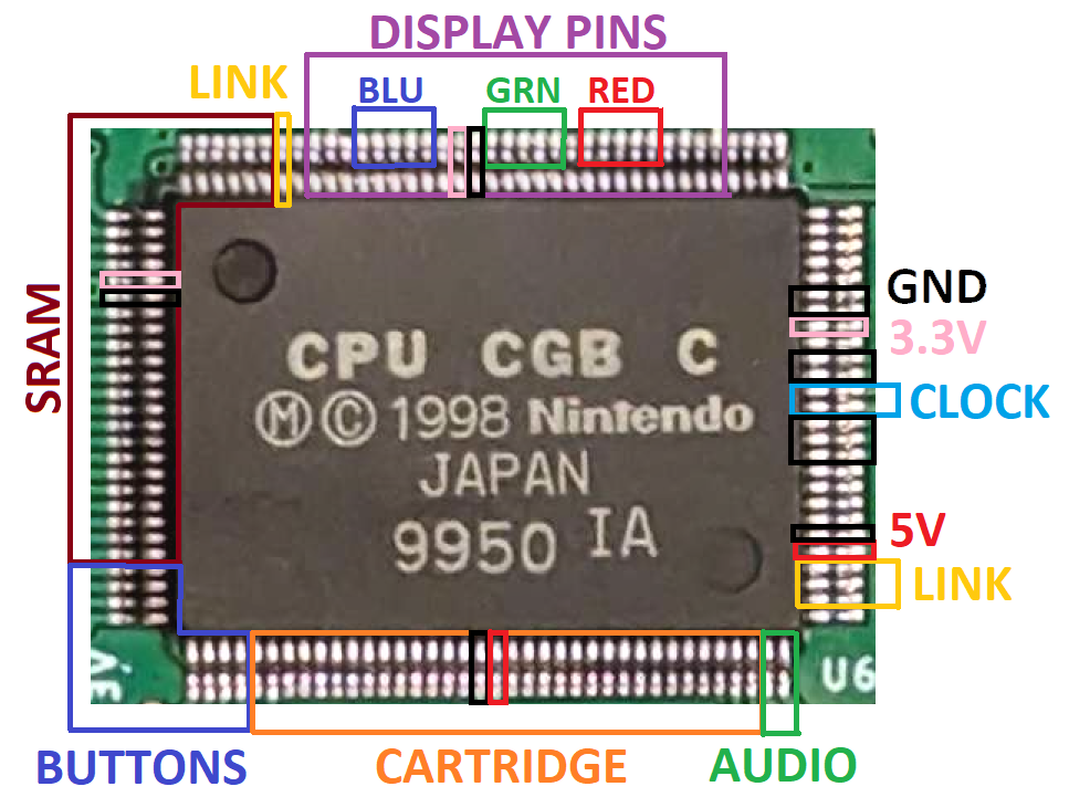
102 |
103 | ## PCB Errors
104 |
105 | ### v1.6 and earlier
106 | - The up/down text for the rocker switch functions is flipped
107 | ### v1.5 and earlier
108 | - The rocker switch can sometimes interfere with the shell. Light trimming on the shell may be required for smooth rocking.
109 | - The BOM for builds v1.5 and earlier is different than the one currently in this repo. Please view the differences in the Excel or .csv file in the root directory.
110 | ### v1.4
111 | - The button contacts are too responsive compared to Nintendo's button style. Use of tactile switches is recommended.
112 |
113 |
114 | ## Bill of Materials
115 |
116 | This should be for reference only. This can be found in the main folder in Excel format. There is also a link in the main folder for a saved Mouser cart with all these parts.
117 |
118 | *Note that this reflects the BOM for v1.6 and later. For earlier revisions, see the BOM Excel or .csv in the root folder of the repository.*
119 |
120 | | Reference Designators | Qty | Value/Part Number | Package | Description | Comment | Source |
121 | | -------------------------------- | --- | ----------------- | ----------- | ------------------ | ----------------------------------------------------------------------------------------------------------------- | ---------------------------------------------------------------------------------------------------------------------------------------------------------------------------------------------------------------------------------------------------------------------------------------------------------------------------- |
122 | | B1-B8 | 8 | SKRRABE010 | | Tactile switch | Optional, can be omitted if you don't want clicky SP-style buttons (SKRRAA is less clicky, SKRRAC is more clicky) | [https://www.mouser.com/ProductDetail/688-SKRRAB](https://www.mouser.com/ProductDetail/688-SKRRAB) |
123 | | BT+, BT- | 2 | | | Battery terminals | Can be salvaged from MGB instead | [https://retrogamerepairshop.com/collections/gbp-power/products/gbp-game-boy-pocket-high-quality-replacement-battery-contact-terminals?variant=37893131305132](https://retrogamerepairshop.com/collections/gbp-power/products/gbp-game-boy-pocket-high-quality-replacement-battery-contact-terminals?variant=37893131305132) |
124 | | C1 | 1 | 18pF | 0603 | Capacitor (MLCC) | Should be X5R (or better); at least 1% tolerance; at least 16V | [https://www.mouser.com/ProductDetail/YAGEO/CC0603FRNPO9BN180?qs=vTakOoo5QyL0KzYUzHPSUw%3D%3D](https://www.mouser.com/ProductDetail/YAGEO/CC0603FRNPO9BN180?qs=vTakOoo5QyL0KzYUzHPSUw%3D%3D) |
125 | | C2, C15, C20 | 3 | 27pF | 0603 | Capacitor (MLCC) | Should be X5R (or better); at least 1% tolerance; at least 16V | [https://www.mouser.com/ProductDetail/603-C0603FRNPO9BN270](https://www.mouser.com/ProductDetail/603-C0603FRNPO9BN270) |
126 | | C3, C12, C24, C43, C52, C53 | 6 | 0.1uF | 0603 | Capacitor (MLCC) | Should be X5R (or better), at least 16V | [https://www.mouser.com/ProductDetail/KEMET/C0603C104M3RACTU?qs=7q2aiX3Gdlh4qBRaMcnohQ%3D%3D](https://www.mouser.com/ProductDetail/KEMET/C0603C104M3RACTU?qs=7q2aiX3Gdlh4qBRaMcnohQ%3D%3D) |
127 | | C4 | 1 | 22pF | 0603 | Capacitor (MLCC) | | [https://www.mouser.com/ProductDetail/YAGEO/CC0603JRNPO9BN220?qs=vTakOoo5QyIVMYOUTI%2F4zA%3D%3D](https://www.mouser.com/ProductDetail/YAGEO/CC0603JRNPO9BN220?qs=vTakOoo5QyIVMYOUTI%2F4zA%3D%3D) |
128 | | C5-C7, C13, C14 | 5 | 100pF | 0603 | Capacitor (MLCC) | | [https://www.mouser.com/ProductDetail/YAGEO/CC0603JPNPO9BN101?qs=7s%252B3O6pAiyAo%2FUxNqKltRA%3D%3D](https://www.mouser.com/ProductDetail/YAGEO/CC0603JPNPO9BN101?qs=7s%252B3O6pAiyAo%2FUxNqKltRA%3D%3D) |
129 | | C8, C21, C26, C27 | 4 | 100uF | 1210 | Capacitor (Tant) | | [https://www.mouser.com/ProductDetail/?qs=rmxM1XIQazfTOF9DkZj0og%3D%3D](https://www.mouser.com/ProductDetail/?qs=rmxM1XIQazfTOF9DkZj0og%3D%3D) |
130 | | C9, C10, C29, C33, C41, C45 | 6 | 0.01uF | 0603 | Capacitor (MLCC) | Should be X5R (or better), at least 16V | [https://www.mouser.com/ProductDetail/KEMET/C0603C103J5RACTU?qs=BimOss5pjlFJEfKhlb7g1g%3D%3D](https://www.mouser.com/ProductDetail/KEMET/C0603C103J5RACTU?qs=BimOss5pjlFJEfKhlb7g1g%3D%3D) |
131 | | C11 | 1 | 22uF | 0805 | Capacitor (MLCC) | | [https://www.mouser.com/ProductDetail/Murata-Electronics/GRM21BR61E226ME44K?qs=hNud%2FORuBR25jDsUehWlrQ%3D%3D](https://www.mouser.com/ProductDetail/Murata-Electronics/GRM21BR61E226ME44K?qs=hNud%2FORuBR25jDsUehWlrQ%3D%3D) |
132 | | C16-C19, C39, C40, C48, C49, C51 | 9 | 1uF | 0603 | Capacitor (MLCC) | Should be X5R (or better), at least 16V | [https://www.mouser.com/ProductDetail/KEMET/C0603C105K3PACTU?qs=STjISULpmtalQKXy67%252B4Cg%3D%3D](https://www.mouser.com/ProductDetail/KEMET/C0603C105K3PACTU?qs=STjISULpmtalQKXy67%252B4Cg%3D%3D) |
133 | | C47 | 1 | 150pF | 0603 | Capacitor (MLCC) | | [https://www.mouser.com/ProductDetail/KEMET/C0603C151J5GACTU?qs=V6nSPVTm7vxbAvL0weNH%252BQ%3D%3D](https://www.mouser.com/ProductDetail/KEMET/C0603C151J5GACTU?qs=V6nSPVTm7vxbAvL0weNH%252BQ%3D%3D) |
134 | | D1 | 1 | PMEG2010AEH | SOD-123 | Schottky diode | Most schottky diodes should be suitable (at least 1A, 16V) | [https://www.mouser.com/ProductDetail/?qs=LOCUfHb8d9u7lcjEnyhX1g%3D%3D](https://www.mouser.com/ProductDetail/?qs=LOCUfHb8d9u7lcjEnyhX1g%3D%3D) |
135 | | D2 | 1 | 151033RS03000 | 3mm | Red LED | | [https://www.mouser.com/ProductDetail/Wurth-Elektronik/151033RS03000?qs=LlUlMxKIyB1%252BAw6bWFN43w%3D%3D](https://www.mouser.com/ProductDetail/Wurth-Elektronik/151033RS03000?qs=LlUlMxKIyB1%252BAw6bWFN43w%3D%3D) |
136 | | EM2-EM4, EM9 | 4 | BLM18BD102SN1D | 0603 | Filter | | [https://www.mouser.com/ProductDetail/Murata-Electronics/BLM18BD102SN1D?qs=h3IWXJJGQQWi4eZyJq6ScQ%3D%3D](https://www.mouser.com/ProductDetail/Murata-Electronics/BLM18BD102SN1D?qs=h3IWXJJGQQWi4eZyJq6ScQ%3D%3D) |
137 | | EM6-EM8 | 3 | FBMH2012HM221-T | 0805 | Filter | Replacement: LCMGA201208T221RG | https://mou.sr/3YT6y8F |
138 | | EM10 | 1 | 744235601 | 1812 | Common mode filter | Can be salvaged from CGB instead | [https://www.mouser.com/ProductDetail/Wurth-Elektronik/744235601?qs=BXmE%252BJ0Y7xYO4MPd53j2NQ%3D%3D](https://www.mouser.com/ProductDetail/Wurth-Elektronik/744235601?qs=BXmE%252BJ0Y7xYO4MPd53j2NQ%3D%3D) |
139 | | F1, F2 | 2 | 1A | 0603 | Fuse | | [https://www.mouser.com/ProductDetail/Vishay-Beyschlag/MFU0603FF01000P100?qs=oI046glRurtlP8n%252B3l7CPg%3D%3D](https://www.mouser.com/ProductDetail/Vishay-Beyschlag/MFU0603FF01000P100?qs=oI046glRurtlP8n%252B3l7CPg%3D%3D) |
140 | | FB1 | 1 | BLA31AG601SN4D | 1206 | Ferrite Bead | | [https://www.mouser.com/ProductDetail/Murata-Electronics/BLA31AG601SN4D?qs=2ahBf5rJw09FDcUVkQibEg%3D%3D](https://www.mouser.com/ProductDetail/Murata-Electronics/BLA31AG601SN4D?qs=2ahBf5rJw09FDcUVkQibEg%3D%3D) |
141 | | P1 | 1 | | | Cart connector | | Salvaged (MGB/CGB) |
142 | | P2 | 1 | 62684-502100AHLF | | FFC connector | Can be salvaged from CGB instead | [https://www.mouser.com/ProductDetail/?qs=HL%252BYNjdyZ0vzwc9E0QYY2g%3D%3D](https://www.mouser.com/ProductDetail/?qs=HL%252BYNjdyZ0vzwc9E0QYY2g%3D%3D) |
143 | | P3 | 1 | | | Link port | Can be salvaged from MGB/CGB instead | [https://retrogamerepairshop.com/collections/gbp-accessories/products/link-cable-replacement-port-for-gbc-gbp-gbl?variant=41808976183468](https://retrogamerepairshop.com/collections/gbp-accessories/products/link-cable-replacement-port-for-gbc-gbp-gbl?variant=41808976183468) |
144 | | P4 | 1 | | | DC Jack | Can be salvaged from MGB/CGB instead | [https://www.aliexpress.us/item/2255800460672253.html?spm=a2g0o.order_list.order_list_main.23.c0c31802sdJmTz&gatewayAdapt=glo2usa&_randl_shipto=US](https://www.aliexpress.us/item/2255800460672253.html?spm=a2g0o.order_list.order_list_main.23.c0c31802sdJmTz&gatewayAdapt=glo2usa&_randl_shipto=US) |
145 | | P5 | 1 | | | Headphone jack | | Salvaged (MGB/CGB) |
146 | | Q1 | 1 | SI2301CDS | SOT23 | P-channel MOSFET | | [https://www.mouser.com/ProductDetail/781-SI2301CDS-E3](https://www.mouser.com/ProductDetail/781-SI2301CDS-E3) |
147 | | R1, R22, R23 | 3 | 1k | 0603 | Resistor | | [https://www.mouser.com/ProductDetail/YAGEO/RC0603FR-071KL?qs=VU8sRB4EgwApHsk4rF%2F3zg%3D%3D](https://www.mouser.com/ProductDetail/YAGEO/RC0603FR-071KL?qs=VU8sRB4EgwApHsk4rF%2F3zg%3D%3D) |
148 | | R2, R25 | 2 | 1.5M | 0603 | Resistor | Recommended at least 1% tolerance | [https://www.mouser.com/ProductDetail/YAGEO/RC0603FR-071M5L?qs=VU8sRB4EgwAP38Z8qzPx9Q%3D%3D](https://www.mouser.com/ProductDetail/YAGEO/RC0603FR-071M5L?qs=VU8sRB4EgwAP38Z8qzPx9Q%3D%3D) |
149 | | R3, R9, R11, R31, R33 | 5 | 18k | 0603 | Resistor | | [https://www.mouser.com/ProductDetail/YAGEO/RC0603FR-1018KL?qs=qpJ%252B%252B%252Bdg6p1T2VMMxU7GeA%3D%3D](https://www.mouser.com/ProductDetail/YAGEO/RC0603FR-1018KL?qs=qpJ%252B%252B%252Bdg6p1T2VMMxU7GeA%3D%3D) |
150 | | R4, R5, R10, R30, R32, R36 | 6 | 100k | 0603 | Resistor | | [https://www.mouser.com/ProductDetail/YAGEO/RC0603FR-07100KL?qs=e1ok2LiJcmaihem8Va5%2Fsw%3D%3D](https://www.mouser.com/ProductDetail/YAGEO/RC0603FR-07100KL?qs=e1ok2LiJcmaihem8Va5%2Fsw%3D%3D) |
151 | | R6 | 1 | 124k | 0603 | Resistor | | [https://www.mouser.com/ProductDetail/YAGEO/RC0603FR-07124KL?qs=IuGqVx9wL0JyCPrDfxkrug%3D%3D](https://www.mouser.com/ProductDetail/YAGEO/RC0603FR-07124KL?qs=IuGqVx9wL0JyCPrDfxkrug%3D%3D) |
152 | | R8 | 1 | 249k | 0603 | Resistor | | [https://www.mouser.com/ProductDetail/YAGEO/RC0603FR-07249KL?qs=diQw95jMAePe17DZWvA4rg%3D%3D](https://www.mouser.com/ProductDetail/YAGEO/RC0603FR-07249KL?qs=diQw95jMAePe17DZWvA4rg%3D%3D) |
153 | | R26 | 1 | 5.6k | 0603 | Resistor | | [https://www.mouser.com/ProductDetail/YAGEO/RC0603FR-075K6L?qs=2cAdsCoAWRHvOVv%2Fp%252BkS0g%3D%3D](https://www.mouser.com/ProductDetail/YAGEO/RC0603FR-075K6L?qs=2cAdsCoAWRHvOVv%2Fp%252BkS0g%3D%3D) |
154 | | R27 | 1 | 100 | 0603 | Resistor | | [https://www.mouser.com/ProductDetail/YAGEO/RC0603FR-07100RL?qs=NEN%2FsE%2FLsvPIwIWKCOS4%2FA%3D%3D](https://www.mouser.com/ProductDetail/YAGEO/RC0603FR-07100RL?qs=NEN%2FsE%2FLsvPIwIWKCOS4%2FA%3D%3D) |
155 | | RA1A, RA1B | 2 | 510 | 0603 | Resistor | | [https://www.mouser.com/ProductDetail/YAGEO/RC0603FR-07510RL?qs=gt6vzsuosg04lV7mPQHzdw%3D%3D](https://www.mouser.com/ProductDetail/YAGEO/RC0603FR-07510RL?qs=gt6vzsuosg04lV7mPQHzdw%3D%3D) |
156 | | RA3 | 1 | 270 (x4) | 1206 | Resistor | | [https://www.mouser.com/ProductDetail/YAGEO/TC164-JR-07270RL?qs=8cPjvKtxWv4v1GF6%2FXOmfA%3D%3D](https://www.mouser.com/ProductDetail/YAGEO/TC164-JR-07270RL?qs=8cPjvKtxWv4v1GF6%2FXOmfA%3D%3D) |
157 | | SP | 1 | | | Speaker | Can be salvaged from MGB/CGB instead | [https://retrogamerepairshop.com/collections/gbp-audio/products/funnyplaying-clear-game-boy-color-speaker?variant=37728953761964](https://retrogamerepairshop.com/collections/gbp-audio/products/funnyplaying-clear-game-boy-color-speaker?variant=37728953761964) |
158 | | SW1 | 1 | | | Power switch | | Salvaged (MGB/CGB) |
159 | | SW2 | 1 | COM-08184 | | Navigation switch | | [https://www.mouser.com/ProductDetail/SparkFun/COM-08184?qs=WyAARYrbSnYOIhcg6ARCiQ%3D%3D](https://www.mouser.com/ProductDetail/SparkFun/COM-08184?qs=WyAARYrbSnYOIhcg6ARCiQ%3D%3D) |
160 | | U1 | 1 | GBC CPU | QFP-128 | CPU | | Salvaged (GBC) |
161 | | U2 | 1 | LH52256CVTXIZ | TSOP-28 | RAM | Can be salvaged from CGB instead | [https://mou.sr/3f8G0Mi](https://mou.sr/3f8G0Mi) |
162 | | U3 | 1 | LM4853 | VSSOP-10 | Audio amplifier | | [https://www.mouser.com/ProductDetail/Texas-Instruments/LM4853MM-NOPB?qs=QbsRYf82W3F2psFI2da2Dw%3D%3D](https://www.mouser.com/ProductDetail/Texas-Instruments/LM4853MM-NOPB?qs=QbsRYf82W3F2psFI2da2Dw%3D%3D) |
163 | | U4 | 1 | NCP161ASN330T1G | SOT23-5 | LDO | Can also use TLV70233QDBVRQ1, probably | [https://www.mouser.com/ProductDetail/863-NCP161ASN330T1G](https://www.mouser.com/ProductDetail/863-NCP161ASN330T1G) |
164 | | U5 | 1 | | | Power Board | Can also use other boards, see github for compatibility notes | [https://github.com/MouseBiteLabs/Pocket-Mouse-Power-Board](https://github.com/MouseBiteLabs/Pocket-Mouse-Power-Board) |
165 | | U6 | 1 | TPS3840DL35 | SOT23-5 | Supervisory IC | | [https://www.mouser.com/ProductDetail/Texas-Instruments/TPS3840DL35DBVR?qs=7MVldsJ5UawbjRj7dP73rA%3D%3D](https://www.mouser.com/ProductDetail/Texas-Instruments/TPS3840DL35DBVR?qs=7MVldsJ5UawbjRj7dP73rA%3D%3D) |
166 | | U7 | 1 | TL331 | SOT23-5 | Comparator | | [https://www.mouser.com/ProductDetail/Texas-Instruments/TL331KDBVT?qs=XGzIaZb%2FFYIdafwjPOKAMg%3D%3D](https://www.mouser.com/ProductDetail/Texas-Instruments/TL331KDBVT?qs=XGzIaZb%2FFYIdafwjPOKAMg%3D%3D) |
167 | | VR1 | 1 | 10k (x2) | | Volume wheel | Can be salvaged from MGB/CGB instead | [https://retrogamerepairshop.com/collections/gbp-accessories/products/game-boy-pocket-color-contrast-volume-wheel-replacement?variant=37893894308012](https://retrogamerepairshop.com/collections/gbp-accessories/products/game-boy-pocket-color-contrast-volume-wheel-replacement?variant=37893894308012) |
168 | | X1 | 1 | 8.388608MHz | 7.5X5-4-PAD | Crystal oscillator | | Salvaged (GBC) |
169 |
170 | ## Revision History
171 |
172 | ### v2.1 - Final Release
173 |
174 | - Added a notch in the bottom of the board for easier routing of LiPo battery leads
175 |
176 | ### v2.0 - Release III
177 |
178 | - Fixed up/down text for rocker switch functionality.
179 | - Changed EM7 connection so it is required for power boards using AAAs *and* power boards using Lipo batteries.
180 | - Use of the DC jack with AAA batteries requires shorting the DC and BT+ holes.
181 | - Added 3.3V to pin 37 on the FFC for compatibility with newer CGS screen kits.
182 | - Reduced hole diameter for volume dial mounting
183 |
184 | ### v1.6 - Release II
185 |
186 | - Added 100 uF capacitor across 5V rail to reduce voltage ripple
187 | - Lowered default maximum volume
188 | - Changed the low battery detection circuit for easier threshold calculations
189 | - Expanded bottom hole for DC jack for compatibility with aftermarket parts
190 | - Shifted some components for easier solderability
191 | - Renamed LED1 to D2
192 |
193 | ### v1.5 - Release I
194 |
195 | - Modified button contacts to feel more OEM-like
196 | - Nudged SW2 to better fit in the shell, extend solder pads for easier assembly
197 | - Flipped locations of the up and down pads for the rocker switch
198 | - Modified battery terminal contacts to match OEM style
199 |
200 | ### v1.4 - Beta III
201 |
202 | - Adjusted hole and part placement for better shell fitment
203 | - Reverted button contacts to Beta I design for better actuation
204 | - Renamed some parts to match OEM descriptions
205 | - Created separate v1.4S version
206 |
207 | ### v1.3 - Beta II
208 |
209 | - Adjusted hole and part placement for better shell fitment
210 | - Changed button pads to mimic OEM
211 | - Modified silkscreen to mimic OEM Game Boy PCBs better
212 | - Changed DC jack round holes to slots
213 |
214 | ### v1.2 - Beta I
215 |
216 | - Restored OEM headphone jack
217 | - Removed extra crystal oscillator pads (it won't fit in the shell)
218 | - Shifted IPS screen kit connector down
219 | - Removed load switch circuit and PTC input
220 |
221 | ### v1.1 - Alpha
222 |
223 | - Changed name from MGBC-LCPU-01 to MGBC-MBL-01
224 | - Flipped power switch to correct orientation
225 | - Corrected power LED indicator dimming (v1.0 was backwards)
226 | - Added pads for tactile buttons
227 | - Added pads for different crystal oscillator package
228 | - Changed headphone jack to new version instead of OEM
229 |
230 | ### v1.0 - Prototype
231 |
232 | - Initial revision
233 |
234 | ## License
235 |
31 |
32 | **Half-silkscreen version:**
33 |
34 |
35 |
36 | ## Customization Options
37 |
38 | This section will explain all of the different customization options available on this board while you assemble.
39 |
40 | ### Enabling Reset Button Functionality
41 |
42 | Bridge the pads labelled "RST" with solder to turn the navigation switch into a reset button whenever you push it in. It's not particularly easy to push the button in, so accidental resets shouldn't be a concern. But if you find yourself accidentally resetting the system, you can remove the solder from the pads to disable it.
43 |
44 | 
45 |
46 | ### Power LED Brightness
47 |
48 | Increase the value of R9 to decrease the brightness of the power LED during normal battery levels. Increase the value of R10 to decrease the brightness of the power LED during low battery levels. It is suggested to try changing resistances in ~10 kΩ increments.
49 |
50 | 
51 |
52 |
53 | ### Tactile Switches
54 |
55 | If you want clicky buttons, like the GBA SP has, then you can install tactile switches onto the button contacts. These are listed as B1-B8 on the BOM. There are three levels of clickiness to choose from, depending on the part number you select - SKRRAAE010 is the "least clicky" with 1 N operating force, SKRRABE010 has 1.6 N of operating force, and SKRRACE010 is the "most clicky" with 2 N of operating force. Note when installing the switches to make sure the little "wings" are oriented correctly as indicated on the board!
56 |
57 | 
58 |
59 | ### Enabling the DC Jack (v2.0 and v2.1 only)
60 |
61 | When making the system for use with AAAs, you must connect the two holes labelled BT+ and DC together with a wire or 0 ohm resistor. This is only required on v2.0 and later boards - v1.6 and earlier do not require this. Shorting these holes together connects the DC jack to the input of the regulator. So if you forget to add it, then your DC jack won't work (which may or may not matter to you anyway). DO NOT SHORT THESE TOGETHER IF USING A LITHIUM-ION BATTERY.
62 |
63 | 
64 |
65 | ### LiPo Support
66 |
67 | Are you using the Game Boy Pocket Power regulator for U5 for LiPo support? Are you sure you want to? Lithium-ion batteries are **dangerous** so if you're going to be using one... you're on your own. You're responsible for using it safely.
68 |
69 | But, I did make it *slightly* easier for you. If you're using either my LiPo board or the GBPP with LiPo, solder wires or headers from the DC and BT+ holes into the power board, thread the wires from the battery through the hole in the board to the power board connections, and remember to **REMOVE EM7** if your board revision is v1.6 or earlier. On v2.0 and v2.1, keep EM7 in place. You'll also need a USB-C adapter PCB to go in place of DC jack.
70 |
71 | 
72 |
73 | Also, to get the power LED to dim at the correct time, remove R6 from the main MGBC board.
74 |
75 | 
76 |
77 | If you're using Nataliethenerd's Safer Charge DC, connect a wire from the "To F1" pad on the back of the board to the BT+ hole on the MGBC, and a wire from the "To 5V" pad on the back of the board to the pad on the USB-C breakout board. Then install the board into the U5 socket as normal.
78 |
79 | 
80 |
81 | ## Assembly References
82 |
83 | Here are a few images that should help clarify the build process, as well as provide some brief technical explanations to guide you in troubleshooting any errors you might have.
84 |
85 | ### Part Placement
86 |
87 | Some of the parts are a bit cramped, and it can be a bit difficult to decipher which part is which. Hopefully this image helps you clarify. (This is a photo from a previous version of the board, so the parts on your board may be slightly nudged from where they are in this image.)
88 |
89 | 
90 |
91 | ### CPU Pin Functions
92 |
93 | This is a bit of a mess, but depending on the problem you're encountering, it could be worth reflowing the pins on the CPU that correspond to the aspect you're having problems with.
94 | - For miscolored screens, reflow the top display pins.
95 | - For *glitchy* screens, or frozen/all-white screens, reflow the SRAM pins.
96 | - If you're missing button inputs, reflow the bottom left corner button pins.
97 | - If you have games that don't start up properly and hang at the Nintendo logo during start-up, display a glitchy Nintendo logo, or randomly freeze during gameplay, reflow the cartridge pins and clean your cartridge connector. The freezing may also be caused by poorly connected SRAM as well.
98 | - Three link port pins are on the bottom right, but there is one lone one at the top.
99 | - In general, reflowing the clock and power pins (colored red, pink, and black) can solve problems as well.
100 |
101 | 
102 |
103 | ## PCB Errors
104 |
105 | ### v1.6 and earlier
106 | - The up/down text for the rocker switch functions is flipped
107 | ### v1.5 and earlier
108 | - The rocker switch can sometimes interfere with the shell. Light trimming on the shell may be required for smooth rocking.
109 | - The BOM for builds v1.5 and earlier is different than the one currently in this repo. Please view the differences in the Excel or .csv file in the root directory.
110 | ### v1.4
111 | - The button contacts are too responsive compared to Nintendo's button style. Use of tactile switches is recommended.
112 |
113 |
114 | ## Bill of Materials
115 |
116 | This should be for reference only. This can be found in the main folder in Excel format. There is also a link in the main folder for a saved Mouser cart with all these parts.
117 |
118 | *Note that this reflects the BOM for v1.6 and later. For earlier revisions, see the BOM Excel or .csv in the root folder of the repository.*
119 |
120 | | Reference Designators | Qty | Value/Part Number | Package | Description | Comment | Source |
121 | | -------------------------------- | --- | ----------------- | ----------- | ------------------ | ----------------------------------------------------------------------------------------------------------------- | ---------------------------------------------------------------------------------------------------------------------------------------------------------------------------------------------------------------------------------------------------------------------------------------------------------------------------- |
122 | | B1-B8 | 8 | SKRRABE010 | | Tactile switch | Optional, can be omitted if you don't want clicky SP-style buttons (SKRRAA is less clicky, SKRRAC is more clicky) | [https://www.mouser.com/ProductDetail/688-SKRRAB](https://www.mouser.com/ProductDetail/688-SKRRAB) |
123 | | BT+, BT- | 2 | | | Battery terminals | Can be salvaged from MGB instead | [https://retrogamerepairshop.com/collections/gbp-power/products/gbp-game-boy-pocket-high-quality-replacement-battery-contact-terminals?variant=37893131305132](https://retrogamerepairshop.com/collections/gbp-power/products/gbp-game-boy-pocket-high-quality-replacement-battery-contact-terminals?variant=37893131305132) |
124 | | C1 | 1 | 18pF | 0603 | Capacitor (MLCC) | Should be X5R (or better); at least 1% tolerance; at least 16V | [https://www.mouser.com/ProductDetail/YAGEO/CC0603FRNPO9BN180?qs=vTakOoo5QyL0KzYUzHPSUw%3D%3D](https://www.mouser.com/ProductDetail/YAGEO/CC0603FRNPO9BN180?qs=vTakOoo5QyL0KzYUzHPSUw%3D%3D) |
125 | | C2, C15, C20 | 3 | 27pF | 0603 | Capacitor (MLCC) | Should be X5R (or better); at least 1% tolerance; at least 16V | [https://www.mouser.com/ProductDetail/603-C0603FRNPO9BN270](https://www.mouser.com/ProductDetail/603-C0603FRNPO9BN270) |
126 | | C3, C12, C24, C43, C52, C53 | 6 | 0.1uF | 0603 | Capacitor (MLCC) | Should be X5R (or better), at least 16V | [https://www.mouser.com/ProductDetail/KEMET/C0603C104M3RACTU?qs=7q2aiX3Gdlh4qBRaMcnohQ%3D%3D](https://www.mouser.com/ProductDetail/KEMET/C0603C104M3RACTU?qs=7q2aiX3Gdlh4qBRaMcnohQ%3D%3D) |
127 | | C4 | 1 | 22pF | 0603 | Capacitor (MLCC) | | [https://www.mouser.com/ProductDetail/YAGEO/CC0603JRNPO9BN220?qs=vTakOoo5QyIVMYOUTI%2F4zA%3D%3D](https://www.mouser.com/ProductDetail/YAGEO/CC0603JRNPO9BN220?qs=vTakOoo5QyIVMYOUTI%2F4zA%3D%3D) |
128 | | C5-C7, C13, C14 | 5 | 100pF | 0603 | Capacitor (MLCC) | | [https://www.mouser.com/ProductDetail/YAGEO/CC0603JPNPO9BN101?qs=7s%252B3O6pAiyAo%2FUxNqKltRA%3D%3D](https://www.mouser.com/ProductDetail/YAGEO/CC0603JPNPO9BN101?qs=7s%252B3O6pAiyAo%2FUxNqKltRA%3D%3D) |
129 | | C8, C21, C26, C27 | 4 | 100uF | 1210 | Capacitor (Tant) | | [https://www.mouser.com/ProductDetail/?qs=rmxM1XIQazfTOF9DkZj0og%3D%3D](https://www.mouser.com/ProductDetail/?qs=rmxM1XIQazfTOF9DkZj0og%3D%3D) |
130 | | C9, C10, C29, C33, C41, C45 | 6 | 0.01uF | 0603 | Capacitor (MLCC) | Should be X5R (or better), at least 16V | [https://www.mouser.com/ProductDetail/KEMET/C0603C103J5RACTU?qs=BimOss5pjlFJEfKhlb7g1g%3D%3D](https://www.mouser.com/ProductDetail/KEMET/C0603C103J5RACTU?qs=BimOss5pjlFJEfKhlb7g1g%3D%3D) |
131 | | C11 | 1 | 22uF | 0805 | Capacitor (MLCC) | | [https://www.mouser.com/ProductDetail/Murata-Electronics/GRM21BR61E226ME44K?qs=hNud%2FORuBR25jDsUehWlrQ%3D%3D](https://www.mouser.com/ProductDetail/Murata-Electronics/GRM21BR61E226ME44K?qs=hNud%2FORuBR25jDsUehWlrQ%3D%3D) |
132 | | C16-C19, C39, C40, C48, C49, C51 | 9 | 1uF | 0603 | Capacitor (MLCC) | Should be X5R (or better), at least 16V | [https://www.mouser.com/ProductDetail/KEMET/C0603C105K3PACTU?qs=STjISULpmtalQKXy67%252B4Cg%3D%3D](https://www.mouser.com/ProductDetail/KEMET/C0603C105K3PACTU?qs=STjISULpmtalQKXy67%252B4Cg%3D%3D) |
133 | | C47 | 1 | 150pF | 0603 | Capacitor (MLCC) | | [https://www.mouser.com/ProductDetail/KEMET/C0603C151J5GACTU?qs=V6nSPVTm7vxbAvL0weNH%252BQ%3D%3D](https://www.mouser.com/ProductDetail/KEMET/C0603C151J5GACTU?qs=V6nSPVTm7vxbAvL0weNH%252BQ%3D%3D) |
134 | | D1 | 1 | PMEG2010AEH | SOD-123 | Schottky diode | Most schottky diodes should be suitable (at least 1A, 16V) | [https://www.mouser.com/ProductDetail/?qs=LOCUfHb8d9u7lcjEnyhX1g%3D%3D](https://www.mouser.com/ProductDetail/?qs=LOCUfHb8d9u7lcjEnyhX1g%3D%3D) |
135 | | D2 | 1 | 151033RS03000 | 3mm | Red LED | | [https://www.mouser.com/ProductDetail/Wurth-Elektronik/151033RS03000?qs=LlUlMxKIyB1%252BAw6bWFN43w%3D%3D](https://www.mouser.com/ProductDetail/Wurth-Elektronik/151033RS03000?qs=LlUlMxKIyB1%252BAw6bWFN43w%3D%3D) |
136 | | EM2-EM4, EM9 | 4 | BLM18BD102SN1D | 0603 | Filter | | [https://www.mouser.com/ProductDetail/Murata-Electronics/BLM18BD102SN1D?qs=h3IWXJJGQQWi4eZyJq6ScQ%3D%3D](https://www.mouser.com/ProductDetail/Murata-Electronics/BLM18BD102SN1D?qs=h3IWXJJGQQWi4eZyJq6ScQ%3D%3D) |
137 | | EM6-EM8 | 3 | FBMH2012HM221-T | 0805 | Filter | Replacement: LCMGA201208T221RG | https://mou.sr/3YT6y8F |
138 | | EM10 | 1 | 744235601 | 1812 | Common mode filter | Can be salvaged from CGB instead | [https://www.mouser.com/ProductDetail/Wurth-Elektronik/744235601?qs=BXmE%252BJ0Y7xYO4MPd53j2NQ%3D%3D](https://www.mouser.com/ProductDetail/Wurth-Elektronik/744235601?qs=BXmE%252BJ0Y7xYO4MPd53j2NQ%3D%3D) |
139 | | F1, F2 | 2 | 1A | 0603 | Fuse | | [https://www.mouser.com/ProductDetail/Vishay-Beyschlag/MFU0603FF01000P100?qs=oI046glRurtlP8n%252B3l7CPg%3D%3D](https://www.mouser.com/ProductDetail/Vishay-Beyschlag/MFU0603FF01000P100?qs=oI046glRurtlP8n%252B3l7CPg%3D%3D) |
140 | | FB1 | 1 | BLA31AG601SN4D | 1206 | Ferrite Bead | | [https://www.mouser.com/ProductDetail/Murata-Electronics/BLA31AG601SN4D?qs=2ahBf5rJw09FDcUVkQibEg%3D%3D](https://www.mouser.com/ProductDetail/Murata-Electronics/BLA31AG601SN4D?qs=2ahBf5rJw09FDcUVkQibEg%3D%3D) |
141 | | P1 | 1 | | | Cart connector | | Salvaged (MGB/CGB) |
142 | | P2 | 1 | 62684-502100AHLF | | FFC connector | Can be salvaged from CGB instead | [https://www.mouser.com/ProductDetail/?qs=HL%252BYNjdyZ0vzwc9E0QYY2g%3D%3D](https://www.mouser.com/ProductDetail/?qs=HL%252BYNjdyZ0vzwc9E0QYY2g%3D%3D) |
143 | | P3 | 1 | | | Link port | Can be salvaged from MGB/CGB instead | [https://retrogamerepairshop.com/collections/gbp-accessories/products/link-cable-replacement-port-for-gbc-gbp-gbl?variant=41808976183468](https://retrogamerepairshop.com/collections/gbp-accessories/products/link-cable-replacement-port-for-gbc-gbp-gbl?variant=41808976183468) |
144 | | P4 | 1 | | | DC Jack | Can be salvaged from MGB/CGB instead | [https://www.aliexpress.us/item/2255800460672253.html?spm=a2g0o.order_list.order_list_main.23.c0c31802sdJmTz&gatewayAdapt=glo2usa&_randl_shipto=US](https://www.aliexpress.us/item/2255800460672253.html?spm=a2g0o.order_list.order_list_main.23.c0c31802sdJmTz&gatewayAdapt=glo2usa&_randl_shipto=US) |
145 | | P5 | 1 | | | Headphone jack | | Salvaged (MGB/CGB) |
146 | | Q1 | 1 | SI2301CDS | SOT23 | P-channel MOSFET | | [https://www.mouser.com/ProductDetail/781-SI2301CDS-E3](https://www.mouser.com/ProductDetail/781-SI2301CDS-E3) |
147 | | R1, R22, R23 | 3 | 1k | 0603 | Resistor | | [https://www.mouser.com/ProductDetail/YAGEO/RC0603FR-071KL?qs=VU8sRB4EgwApHsk4rF%2F3zg%3D%3D](https://www.mouser.com/ProductDetail/YAGEO/RC0603FR-071KL?qs=VU8sRB4EgwApHsk4rF%2F3zg%3D%3D) |
148 | | R2, R25 | 2 | 1.5M | 0603 | Resistor | Recommended at least 1% tolerance | [https://www.mouser.com/ProductDetail/YAGEO/RC0603FR-071M5L?qs=VU8sRB4EgwAP38Z8qzPx9Q%3D%3D](https://www.mouser.com/ProductDetail/YAGEO/RC0603FR-071M5L?qs=VU8sRB4EgwAP38Z8qzPx9Q%3D%3D) |
149 | | R3, R9, R11, R31, R33 | 5 | 18k | 0603 | Resistor | | [https://www.mouser.com/ProductDetail/YAGEO/RC0603FR-1018KL?qs=qpJ%252B%252B%252Bdg6p1T2VMMxU7GeA%3D%3D](https://www.mouser.com/ProductDetail/YAGEO/RC0603FR-1018KL?qs=qpJ%252B%252B%252Bdg6p1T2VMMxU7GeA%3D%3D) |
150 | | R4, R5, R10, R30, R32, R36 | 6 | 100k | 0603 | Resistor | | [https://www.mouser.com/ProductDetail/YAGEO/RC0603FR-07100KL?qs=e1ok2LiJcmaihem8Va5%2Fsw%3D%3D](https://www.mouser.com/ProductDetail/YAGEO/RC0603FR-07100KL?qs=e1ok2LiJcmaihem8Va5%2Fsw%3D%3D) |
151 | | R6 | 1 | 124k | 0603 | Resistor | | [https://www.mouser.com/ProductDetail/YAGEO/RC0603FR-07124KL?qs=IuGqVx9wL0JyCPrDfxkrug%3D%3D](https://www.mouser.com/ProductDetail/YAGEO/RC0603FR-07124KL?qs=IuGqVx9wL0JyCPrDfxkrug%3D%3D) |
152 | | R8 | 1 | 249k | 0603 | Resistor | | [https://www.mouser.com/ProductDetail/YAGEO/RC0603FR-07249KL?qs=diQw95jMAePe17DZWvA4rg%3D%3D](https://www.mouser.com/ProductDetail/YAGEO/RC0603FR-07249KL?qs=diQw95jMAePe17DZWvA4rg%3D%3D) |
153 | | R26 | 1 | 5.6k | 0603 | Resistor | | [https://www.mouser.com/ProductDetail/YAGEO/RC0603FR-075K6L?qs=2cAdsCoAWRHvOVv%2Fp%252BkS0g%3D%3D](https://www.mouser.com/ProductDetail/YAGEO/RC0603FR-075K6L?qs=2cAdsCoAWRHvOVv%2Fp%252BkS0g%3D%3D) |
154 | | R27 | 1 | 100 | 0603 | Resistor | | [https://www.mouser.com/ProductDetail/YAGEO/RC0603FR-07100RL?qs=NEN%2FsE%2FLsvPIwIWKCOS4%2FA%3D%3D](https://www.mouser.com/ProductDetail/YAGEO/RC0603FR-07100RL?qs=NEN%2FsE%2FLsvPIwIWKCOS4%2FA%3D%3D) |
155 | | RA1A, RA1B | 2 | 510 | 0603 | Resistor | | [https://www.mouser.com/ProductDetail/YAGEO/RC0603FR-07510RL?qs=gt6vzsuosg04lV7mPQHzdw%3D%3D](https://www.mouser.com/ProductDetail/YAGEO/RC0603FR-07510RL?qs=gt6vzsuosg04lV7mPQHzdw%3D%3D) |
156 | | RA3 | 1 | 270 (x4) | 1206 | Resistor | | [https://www.mouser.com/ProductDetail/YAGEO/TC164-JR-07270RL?qs=8cPjvKtxWv4v1GF6%2FXOmfA%3D%3D](https://www.mouser.com/ProductDetail/YAGEO/TC164-JR-07270RL?qs=8cPjvKtxWv4v1GF6%2FXOmfA%3D%3D) |
157 | | SP | 1 | | | Speaker | Can be salvaged from MGB/CGB instead | [https://retrogamerepairshop.com/collections/gbp-audio/products/funnyplaying-clear-game-boy-color-speaker?variant=37728953761964](https://retrogamerepairshop.com/collections/gbp-audio/products/funnyplaying-clear-game-boy-color-speaker?variant=37728953761964) |
158 | | SW1 | 1 | | | Power switch | | Salvaged (MGB/CGB) |
159 | | SW2 | 1 | COM-08184 | | Navigation switch | | [https://www.mouser.com/ProductDetail/SparkFun/COM-08184?qs=WyAARYrbSnYOIhcg6ARCiQ%3D%3D](https://www.mouser.com/ProductDetail/SparkFun/COM-08184?qs=WyAARYrbSnYOIhcg6ARCiQ%3D%3D) |
160 | | U1 | 1 | GBC CPU | QFP-128 | CPU | | Salvaged (GBC) |
161 | | U2 | 1 | LH52256CVTXIZ | TSOP-28 | RAM | Can be salvaged from CGB instead | [https://mou.sr/3f8G0Mi](https://mou.sr/3f8G0Mi) |
162 | | U3 | 1 | LM4853 | VSSOP-10 | Audio amplifier | | [https://www.mouser.com/ProductDetail/Texas-Instruments/LM4853MM-NOPB?qs=QbsRYf82W3F2psFI2da2Dw%3D%3D](https://www.mouser.com/ProductDetail/Texas-Instruments/LM4853MM-NOPB?qs=QbsRYf82W3F2psFI2da2Dw%3D%3D) |
163 | | U4 | 1 | NCP161ASN330T1G | SOT23-5 | LDO | Can also use TLV70233QDBVRQ1, probably | [https://www.mouser.com/ProductDetail/863-NCP161ASN330T1G](https://www.mouser.com/ProductDetail/863-NCP161ASN330T1G) |
164 | | U5 | 1 | | | Power Board | Can also use other boards, see github for compatibility notes | [https://github.com/MouseBiteLabs/Pocket-Mouse-Power-Board](https://github.com/MouseBiteLabs/Pocket-Mouse-Power-Board) |
165 | | U6 | 1 | TPS3840DL35 | SOT23-5 | Supervisory IC | | [https://www.mouser.com/ProductDetail/Texas-Instruments/TPS3840DL35DBVR?qs=7MVldsJ5UawbjRj7dP73rA%3D%3D](https://www.mouser.com/ProductDetail/Texas-Instruments/TPS3840DL35DBVR?qs=7MVldsJ5UawbjRj7dP73rA%3D%3D) |
166 | | U7 | 1 | TL331 | SOT23-5 | Comparator | | [https://www.mouser.com/ProductDetail/Texas-Instruments/TL331KDBVT?qs=XGzIaZb%2FFYIdafwjPOKAMg%3D%3D](https://www.mouser.com/ProductDetail/Texas-Instruments/TL331KDBVT?qs=XGzIaZb%2FFYIdafwjPOKAMg%3D%3D) |
167 | | VR1 | 1 | 10k (x2) | | Volume wheel | Can be salvaged from MGB/CGB instead | [https://retrogamerepairshop.com/collections/gbp-accessories/products/game-boy-pocket-color-contrast-volume-wheel-replacement?variant=37893894308012](https://retrogamerepairshop.com/collections/gbp-accessories/products/game-boy-pocket-color-contrast-volume-wheel-replacement?variant=37893894308012) |
168 | | X1 | 1 | 8.388608MHz | 7.5X5-4-PAD | Crystal oscillator | | Salvaged (GBC) |
169 |
170 | ## Revision History
171 |
172 | ### v2.1 - Final Release
173 |
174 | - Added a notch in the bottom of the board for easier routing of LiPo battery leads
175 |
176 | ### v2.0 - Release III
177 |
178 | - Fixed up/down text for rocker switch functionality.
179 | - Changed EM7 connection so it is required for power boards using AAAs *and* power boards using Lipo batteries.
180 | - Use of the DC jack with AAA batteries requires shorting the DC and BT+ holes.
181 | - Added 3.3V to pin 37 on the FFC for compatibility with newer CGS screen kits.
182 | - Reduced hole diameter for volume dial mounting
183 |
184 | ### v1.6 - Release II
185 |
186 | - Added 100 uF capacitor across 5V rail to reduce voltage ripple
187 | - Lowered default maximum volume
188 | - Changed the low battery detection circuit for easier threshold calculations
189 | - Expanded bottom hole for DC jack for compatibility with aftermarket parts
190 | - Shifted some components for easier solderability
191 | - Renamed LED1 to D2
192 |
193 | ### v1.5 - Release I
194 |
195 | - Modified button contacts to feel more OEM-like
196 | - Nudged SW2 to better fit in the shell, extend solder pads for easier assembly
197 | - Flipped locations of the up and down pads for the rocker switch
198 | - Modified battery terminal contacts to match OEM style
199 |
200 | ### v1.4 - Beta III
201 |
202 | - Adjusted hole and part placement for better shell fitment
203 | - Reverted button contacts to Beta I design for better actuation
204 | - Renamed some parts to match OEM descriptions
205 | - Created separate v1.4S version
206 |
207 | ### v1.3 - Beta II
208 |
209 | - Adjusted hole and part placement for better shell fitment
210 | - Changed button pads to mimic OEM
211 | - Modified silkscreen to mimic OEM Game Boy PCBs better
212 | - Changed DC jack round holes to slots
213 |
214 | ### v1.2 - Beta I
215 |
216 | - Restored OEM headphone jack
217 | - Removed extra crystal oscillator pads (it won't fit in the shell)
218 | - Shifted IPS screen kit connector down
219 | - Removed load switch circuit and PTC input
220 |
221 | ### v1.1 - Alpha
222 |
223 | - Changed name from MGBC-LCPU-01 to MGBC-MBL-01
224 | - Flipped power switch to correct orientation
225 | - Corrected power LED indicator dimming (v1.0 was backwards)
226 | - Added pads for tactile buttons
227 | - Added pads for different crystal oscillator package
228 | - Changed headphone jack to new version instead of OEM
229 |
230 | ### v1.0 - Prototype
231 |
232 | - Initial revision
233 |
234 | ## License
235 | 
This work is licensed under a Creative Commons Attribution-ShareAlike 4.0 International License. You are able to copy and redistribute the material in any medium or format, as well as remix, transform, or build upon the material for any purpose (even commercial) - but you **must** give appropriate credit, provide a link to the license, and indicate if any changes were made.
236 |
237 | ©MouseBiteLabs 2023
238 |
--------------------------------------------------------------------------------
/MGBC_BOM.csv:
--------------------------------------------------------------------------------
1 | ,,,,,Cart link:,https://www.mouser.com/ProjectManager/ProjectDetail.aspx?AccessID=854e7f6cf9,
2 | Reference Designators,Qty,Value/Part Number,Package,Description,Comment,Source,
3 | B1-B8,8,SKRRABE010,,Tactile switch,"Optional, can be omitted if you don't want clicky SP-style buttons (SKRRAA is less clicky, SKRRAC is more clicky)",https://www.mouser.com/ProductDetail/688-SKRRAB,
4 | "BT+, BT-",2,,,Battery terminals,Can be salvaged from MGB instead,https://retrogamerepairshop.com/collections/gbp-power/products/gbp-game-boy-pocket-high-quality-replacement-battery-contact-terminals?variant=37893131305132,
5 | C1,1,18pF,0603,Capacitor (MLCC),Should be X5R (or better); at least 1% tolerance; at least 16V,https://www.mouser.com/ProductDetail/YAGEO/CC0603FRNPO9BN180?qs=vTakOoo5QyL0KzYUzHPSUw%3D%3D,
6 | "C2, C15, C20",3,27pF,0603,Capacitor (MLCC),Should be X5R (or better); at least 1% tolerance; at least 16V,https://www.mouser.com/ProductDetail/603-C0603FRNPO9BN270,
7 | "C3, C12, C24, C43, C52, C53",6,0.1uF,0603,Capacitor (MLCC),"Should be X5R (or better), at least 16V",https://www.mouser.com/ProductDetail/KEMET/C0603C104M3RACTU?qs=7q2aiX3Gdlh4qBRaMcnohQ%3D%3D,
8 | C4,1,22pF,0603,Capacitor (MLCC),,https://www.mouser.com/ProductDetail/YAGEO/CC0603JRNPO9BN220?qs=vTakOoo5QyIVMYOUTI%2F4zA%3D%3D,
9 | "C5-C7, C13, C14",5,100pF,0603,Capacitor (MLCC),,https://www.mouser.com/ProductDetail/YAGEO/CC0603JPNPO9BN101?qs=7s%252B3O6pAiyAo%2FUxNqKltRA%3D%3D,
10 | "C8, C21, C26, C27",4,100uF,1210,Capacitor (Tant),,https://www.mouser.com/ProductDetail/?qs=rmxM1XIQazfTOF9DkZj0og%3D%3D,
11 | "C9, C10, C29, C33, C41, C45",6,0.01uF,0603,Capacitor (MLCC),"Should be X5R (or better), at least 16V",https://www.mouser.com/ProductDetail/KEMET/C0603C103J5RACTU?qs=BimOss5pjlFJEfKhlb7g1g%3D%3D,
12 | C11,1,22uF,0805,Capacitor (MLCC),,https://www.mouser.com/ProductDetail/Murata-Electronics/GRM21BR61E226ME44K?qs=hNud%2FORuBR25jDsUehWlrQ%3D%3D,
13 | "C16-C19, C39, C40, C48, C49, C51",9,1uF,0603,Capacitor (MLCC),"Should be X5R (or better), at least 16V",https://www.mouser.com/ProductDetail/KEMET/C0603C105K3PACTU?qs=STjISULpmtalQKXy67%252B4Cg%3D%3D,
14 | C47,1,150pF,0603,Capacitor (MLCC),,https://www.mouser.com/ProductDetail/KEMET/C0603C151J5GACTU?qs=V6nSPVTm7vxbAvL0weNH%252BQ%3D%3D,
15 | D1,1,PMEG2010AEH,SOD-123,Schottky diode,"Most schottky diodes should be suitable (at least 1A, 16V)",https://www.mouser.com/ProductDetail/?qs=LOCUfHb8d9u7lcjEnyhX1g%3D%3D,
16 | D2,1,151033RS03000,3mm,Red LED,,https://www.mouser.com/ProductDetail/Wurth-Elektronik/151033RS03000?qs=LlUlMxKIyB1%252BAw6bWFN43w%3D%3D,
17 | "EM2-EM4, EM9",4,BLM18BD102SN1D,0603,Filter,,https://www.mouser.com/ProductDetail/Murata-Electronics/BLM18BD102SN1D?qs=h3IWXJJGQQWi4eZyJq6ScQ%3D%3D,
18 | EM6-EM8,3,LCMGA201208T221RG,0805,Filter,Replacement: Z0805C221BPWZT,https://www.mouser.com/ProductDetail/TAIYO-YUDEN/LCMGA201208T221RG?qs=tlsG%2FOw5FFhaNdb0vekDOQ%3D%3D,
19 | EM10,1,744235601,1812,Common mode filter,Can be salvaged from CGB instead,https://www.mouser.com/ProductDetail/Wurth-Elektronik/744235601?qs=BXmE%252BJ0Y7xYO4MPd53j2NQ%3D%3D,
20 | "F1, F2",2,1A,0603,Fuse,,https://www.mouser.com/ProductDetail/Vishay-Beyschlag/MFU0603FF01000P100?qs=oI046glRurtlP8n%252B3l7CPg%3D%3D,
21 | FB1,1,BLA31AG601SN4D,1206,Ferrite Bead,,https://www.mouser.com/ProductDetail/Murata-Electronics/BLA31AG601SN4D?qs=2ahBf5rJw09FDcUVkQibEg%3D%3D,
22 | P1,1,,,Cart connector,,Salvaged (MGB/CGB),
23 | P2,1,62684-502100AHLF,,FFC connector,Can be salvaged from CGB instead,https://www.mouser.com/ProductDetail/?qs=HL%252BYNjdyZ0vzwc9E0QYY2g%3D%3D,
24 | P3,1,,,Link port,Can be salvaged from MGB/CGB instead,https://retrogamerepairshop.com/collections/gbp-accessories/products/link-cable-replacement-port-for-gbc-gbp-gbl?variant=41808976183468,
25 | P4,1,,,DC Jack,Can be salvaged from MGB/CGB instead,https://www.aliexpress.us/item/2255800460672253.html?spm=a2g0o.order_list.order_list_main.23.c0c31802sdJmTz&gatewayAdapt=glo2usa&_randl_shipto=US,
26 | P5,1,,,Headphone jack,,Salvaged (MGB/CGB),
27 | Q1,1,SI2301CDS,SOT23,P-channel MOSFET,,https://www.mouser.com/ProductDetail/781-SI2301CDS-E3,
28 | "R1, R22, R23",3,1k,0603,Resistor,,https://www.mouser.com/ProductDetail/YAGEO/RC0603FR-071KL?qs=VU8sRB4EgwApHsk4rF%2F3zg%3D%3D,
29 | "R2, R25",2,1.5M,0603,Resistor,Recommended at least 1% tolerance,https://www.mouser.com/ProductDetail/YAGEO/RC0603FR-071M5L?qs=VU8sRB4EgwAP38Z8qzPx9Q%3D%3D,
30 | "R3, R9, R11, R31, R33",5,18k,0603,Resistor,,https://www.mouser.com/ProductDetail/YAGEO/RC0603FR-1018KL?qs=qpJ%252B%252B%252Bdg6p1T2VMMxU7GeA%3D%3D,
31 | "R4, R5, R10, R30, R32, R36",6,100k,0603,Resistor,,https://www.mouser.com/ProductDetail/YAGEO/RC0603FR-07100KL?qs=e1ok2LiJcmaihem8Va5%2Fsw%3D%3D,
32 | R6,1,124k,0603,Resistor,,https://www.mouser.com/ProductDetail/YAGEO/RC0603FR-07124KL?qs=IuGqVx9wL0JyCPrDfxkrug%3D%3D,
33 | R8,1,249k,0603,Resistor,,https://www.mouser.com/ProductDetail/YAGEO/RC0603FR-07249KL?qs=diQw95jMAePe17DZWvA4rg%3D%3D,
34 | R26,1,5.6k,0603,Resistor,,https://www.mouser.com/ProductDetail/YAGEO/RC0603FR-075K6L?qs=2cAdsCoAWRHvOVv%2Fp%252BkS0g%3D%3D,
35 | R27,1,100,0603,Resistor,,https://www.mouser.com/ProductDetail/YAGEO/RC0603FR-07100RL?qs=NEN%2FsE%2FLsvPIwIWKCOS4%2FA%3D%3D,
36 | "RA1A, RA1B",2,510,0603,Resistor,,https://www.mouser.com/ProductDetail/YAGEO/RC0603FR-07510RL?qs=gt6vzsuosg04lV7mPQHzdw%3D%3D,
37 | RA3,1,270 (x4),1206,Resistor,,https://www.mouser.com/ProductDetail/YAGEO/TC164-JR-07270RL?qs=8cPjvKtxWv4v1GF6%2FXOmfA%3D%3D,
38 | SP,1,,,Speaker,Can be salvaged from MGB/CGB instead,https://retrogamerepairshop.com/collections/gbp-audio/products/funnyplaying-clear-game-boy-color-speaker?variant=37728953761964,
39 | SW1,1,,,Power switch,,Salvaged (MGB/CGB),
40 | SW2,1,COM-08184,,Navigation switch,,https://www.mouser.com/ProductDetail/SparkFun/COM-08184?qs=WyAARYrbSnYOIhcg6ARCiQ%3D%3D,
41 | U1,1,GBC CPU,QFP-128,CPU,,Salvaged (GBC),
42 | U2,1,LH52256CVTXIZ,TSOP-28,RAM,Can be salvaged from CGB instead,https://mou.sr/3f8G0Mi,
43 | U3,1,LM4853,VSSOP-10,Audio amplifier,,https://www.mouser.com/ProductDetail/Texas-Instruments/LM4853MM-NOPB?qs=QbsRYf82W3F2psFI2da2Dw%3D%3D,
44 | U4,1,NCP161ASN330T1G,SOT23-5,LDO,"Can also use TLV70233QDBVRQ1, probably",https://www.mouser.com/ProductDetail/863-NCP161ASN330T1G,
45 | U5,1,,,Power Board,"Can also use other boards, see github for compatibility notes",https://github.com/MouseBiteLabs/Pocket-Mouse-Power-Board,
46 | U6,1,TPS3840DL35,SOT23-5,Supervisory IC,,https://www.mouser.com/ProductDetail/Texas-Instruments/TPS3840DL35DBVR?qs=7MVldsJ5UawbjRj7dP73rA%3D%3D,
47 | U7,1,TL331,SOT23-5,Comparator,,https://www.mouser.com/ProductDetail/Texas-Instruments/TL331KDBVT?qs=XGzIaZb%2FFYIdafwjPOKAMg%3D%3D,
48 | VR1,1,10k (x2),,Volume wheel,Can be salvaged from MGB/CGB instead,https://retrogamerepairshop.com/collections/gbp-accessories/products/game-boy-pocket-color-contrast-volume-wheel-replacement?variant=37893894308012,
49 | X1,1,8.388608MHz,7.5X5-4-PAD,Crystal oscillator,,Salvaged (GBC),
50 |
--------------------------------------------------------------------------------
/MGBC_BOM.xlsx:
--------------------------------------------------------------------------------
https://raw.githubusercontent.com/MouseBiteLabs/Game-Boy-Pocket-Color/e438e8a5643067cf37bb57570c9ef4bc98b809fd/MGBC_BOM.xlsx
--------------------------------------------------------------------------------
/README.md:
--------------------------------------------------------------------------------
1 | # Game Boy Pocket Color
2 |
3 | 
4 |
5 | My DMGC project put a Game Boy Color put into an original Game Boy shell. But then I said, "Hey! This is neat, but I would rather it be small and cramped and have shorter battery life!" Enter the MGBC, or Pocket Color - a Game Boy Pocket (model name MGB) with the guts of a Game Boy Color (GBC). The PCB here is an original creation with some new features, though the concept and implementation of the "MGBC" or "Pocket Color" has been around for a while! Here are the project goals:
6 |
7 | - A Game Boy Pocket aesthetic, using the original Game Boy Pocket shell and interfaces (link port, volume wheel, power switch, etc.), but with the capability of playing both Game Boy and Game Boy Color games.
8 | - A nice, large IPS screen – the GBC Q5 XL IPS Backlight with OSD kit – with brightness and color palette control via the "navigation switch" housed where the contrast wheel used to be. (I will refer to the PCB attached to the Q5 screen as the “Q5 board”)
9 | - A modernized, efficient switch mode power supply that can run off 2x AAA batteries or input from the DC jack, just like the original MGB. Testing shows that playing with NiMH AAA batteries can yield about 3.5 hours of gameplay at normal settings.
10 | - Louder, cleaner sound through a modern audio amplifier.
11 | - The option for tactile switches for the face buttons - like the GBA SP.
12 | - No major externally viewable case modifications, to keep the OEM look and feel, outside of the screen, as much as possible.
13 |
14 | All gerbers and source files can be found in this repo, as this project is fully open source. These PCB files and notes about the board, including customizations **and some troubleshooting tips**, can be found in the PCB folder. Technical documentation of the board can be found in the Technical folder.
15 |
16 | **Do you want to make one?** Then you NEED TO READ this entire page. Seriously. Before asking a question, please review the FAQ at the bottom of the README for answers to.... frequently asked questions. Please try to find your answer in this repository - 95% of the time someone asks me something it's answered here already.
17 |
18 | ## Disclaimer
19 |
20 | Before I go any further, please read this VERY important disclaimer, **IN IT'S ENTIRETY,** if you are thinking about making this yourself. **Don't let this picture happen to you!**
21 |
22 | 
23 |
24 | I made this project first and foremost for my own purposes. Nearly all of the features I have included are things I personally wanted. I have tried my hardest to make the project modular, if others would like to improve or change things easily, and I have also tried very hard to make the design somewhat less prone to potential errors during assembly. But in the end, every decision I made was for what I wanted the final product to be, with my skill level in mind.
25 |
26 | So if you choose to build this project yourself, be warned - this is a considerably advanced, and expensive build. You must be comfortable with the fact that you may lose or damage expensive components. You are 100% liable for any damage done to your property or yourself. I am not responsible for any damage or loss of property incurred while attempting this project, or after completion of the project - you alone accept all risk. If you're *at all* questioning wether or not you can successfully attempt this project, please first practice with the Pocket Mouse Power Board - this requires no original Game Boy parts, and the total parts cost of the board is less than $10. And before you dismantle a Game Boy, solder the FFC connector on the top of the MGBC board to make sure you are comfortable with long rows of fine pitch pins, as it is the same pin pitch as the much more expensive and important CPU. **If you have any difficulty assembling either the power board or the FFC connector, I highly discourage attempting the rest of the build.**
27 |
28 | Furthermore, while I am confident in this design, I cannot claim full compatibility with every system configuration. **Especially if you decide to add a lithium-ion battery.** And there may be latent issues that have yet to crop up. If you see anything I may have missed, or some dubious design choice, feel free to ask questions or comment as such - feedback is appreciated, corrections are welcome.
29 |
30 | 
31 |
32 | In summation: **DO NOT attempt this project if you are uncomfortable or inexperienced with detailed electronics troubleshooting, or are not proficient in soldering! This is in NO WAY a beginner's project. You will AT MINIMUM need to be proficient in drag soldering and hot air reflowing. If you have not gained proficiency in these soldering skills, DO NOT ATTEMPT THIS PROJECT. You accept all risks and costs associated to this build if you choose to attempt it.**
33 |
34 | (These parts are *tiny*. Quarter for scale - do not install a quarter in your final build.)
35 |
36 | 
37 |
38 | ## Bill of Materials (BOM)
39 |
40 | There are a handful of categories for the parts you need for this build. Please review all of them! The total BOM cost will come out to anywhere between $100 and $200 (NOT including the cost of a donor Game Boy Color console!) depending on the options you choose, which OEM parts you re-use, and any potential deals you can get on certain parts. Note that with the exception of a few components from a donor Game Boy Color, *most* of the electronic parts are brand new.
41 |
42 | ### I. Circuit Boards
43 |
44 | First and foremost, you will need two brand new circuit boards for this build:
45 | - the main MGBC circuit board, and
46 | - a power supply board that fits in the U5 socket on the MGBC board (like my Pocket Mouse Power Board, or other power supply boards from other creators - check the Compatibility section below for more information. )
47 |
48 | **I don't recommend using an original power board from a Game Boy!**
49 |
50 | Again, I sell the MGBC board and my regulator board on my Etsy store. You can alternatively use the files in the MGBC PCB folder to order it yourself. Please see the MGBC PCB folder for more info.
51 |
52 |
53 |
54 | And finally, insideGadgets sells these boards partially assembled!
55 |
56 |  57 |
58 | ### Information on Older Revisions
59 |
60 | The current revision is v2.1, but you may have an earlier board (if you bought one from me, rest assured it will work perfectly fine - most of the changes between for-sale revisions are inconsequential to the end user). The BOM has changed slightly for v1.6 and later boards, compared to previous revisions. Please view the Excel and/or .csv file above for BOM information (or contact me). Here's a short list of information about the older boards, and what is required/recommended when using them:
61 |
62 | | Revision | Recommendations |
63 | | ---- | ---------------------------------------------------------------------------------------------------------------------------- |
64 | | v1.0 | You are a masochist. You're on your own for this one. |
65 | | v1.1 | Are you me? No? Then did you rob my house? |
66 | | v1.2 | You're one of the beloved beta testers. You didn't build it yet? For shame. Contact me. |
67 | | v1.3 | These should be practice boards only. |
68 | | v1.4 | Use tactile buttons. Minor shell trimming may be required for volume dial and rocker switch. |
69 | | v1.5 | Minor shell trimming may be required for volume dial and rocker switch. |
70 | | v1.6 | No important differences compared to the latest revision, but check EM7 and DC/BT+ requirements! |
71 | | v2.0 | No important differences compared to the latest revision. |
72 |
73 | ### II. Brand New Electronic Parts
74 |
75 | The MGBC board uses mostly all-new components. This is not a direct-transfer board. The master BOM with every electronic component required for the main MGBC circuit board is provided in the folder in Excel format. Note that some parts may be out of stock at the links provided, but many can be found at alternate other retailers online, or have a proper substitute. Here is a saved cart from Mouser that contains all the parts in the BOM Excel, including some duplicates: https://www.mouser.com/ProjectManager/ProjectDetail.aspx?AccessID=854e7f6cf9
76 |
77 | *Note: This cart link is for v1.6, v2.0, and v2.1 boards. Please check out the BOM Excel or .csv file above for information about v1.5 and earlier.*
78 |
79 | Double check to see if any parts are missing, and consider ordering multiples of some parts. Also, there are some parts you may want to remove (like the tactile switches). **If a part is backordered, or out of stock** - check the Excel file, or the BOM listed at the bottom of the MGBC PCB folder. There may be alternate part options listed. You can also check for stock at places like Digikey, Newark, or LCSC. And you can always use Octopart.com to help find in-stock parts at other websites. Please understand that I can't maintain the cart for every out-of-stock part, so please do some research :)
80 |
81 | Also note, while I do recommend the board, this BOM does not include parts for the Pocket Mouse Power Board. Please review my github on that board for more information if you wish to use it for your power supply!
82 |
83 | ### III. Game Boy Electronic Parts
84 |
85 | *Despite this being a **Pocket** Color, you don't actually need a Game Boy Pocket. However, this project **does require** at minimum a Game Boy Color.*
86 |
87 | There are a handful of parts that I have not located aftermarket substitutes for, and will therefore necessitate an original Game Boy console to salvage from. Please note that removing these parts is not a trivial task, and **requires advanced soldering and desoldering skills to be successful.**
88 |
89 | The following parts are required from an original Game Boy Color console:
90 |
91 | - U1 – CGB CPU (all revisions *except* REV E, which is *incompatible*)
92 | - X1 – 8.388 MHz crystal oscillator
93 |
94 | The following parts are required from an original Game Boy Color **OR** Game Boy Pocket console:
95 |
96 | - P1 – Cartridge connector
97 | - P5 – Headphone jack
98 |
99 | The following parts can be salvaged from a Game Boy Color, but newly manufactured commercial off-the-shelf options exist:
100 |
101 | - U2 – LH52256CVTXIZ (SRAM); alternate: https://mou.sr/3f8G0Mi
102 | - EM10 – input filter; alternate: https://mou.sr/3FiMvXw
103 |
104 | The following parts can be salvaged from a Game Boy Color *or* Game Boy Pocket, but aftermarket options exist:
105 |
106 | - VR1 – Volume dial
107 | - SW1 – Power switch
108 | - P3 – Link port
109 | - P4 – DC jack
110 |
111 | ### IV. External Build Parts
112 |
113 | The following is the high-level BOM - basically, the Game Boy part. Note that parts that deviate from the ones listed here (like different shell designs) might necessitate different fitment modifications, or end up being incompatible. Note that this list is not a comprehensive list of all the places you can get these parts. I encourage you to search around if you can't find what you want here.
114 |
115 | - **Shell:** I generally recommend the Funnyplaying "IPS Ready" ones if you don't want to trim anything. If you don't use these, then you're on your own for how to prepare it - generally, you can follow guides for preparing a Pocket for an IPS screen kit.
116 | - RGRS: FunnyPlaying Game Boy Pocket IPS Backlight Ready Shell Housing No Cut
117 | - FunnyPlaying: GBP RETRO PIXEL IPS CUSTOM SHELL
118 | - **Screen Kit:** This is the important one. You need this specific type of kit - the Q5 IPS with OSD. It goes by many names, the maker is Hispeedido (*not* FunnyPlaying). Kits that have the screen laminated to a GBC lens are *not* compatible, but kits that include a lit-up logo on the bottom part of the screen are fine to use. Make sure you DO NOT get the Game Boy Pocket version - it is not compatible! Also, be sure to test this screen kit before installing it, preferrably with an original Game Boy Color. Sometimes they arrive damaged, and once you've installed, it may not be possible to get a refund.
119 | - RGRS: GBC Q5 XL IPS Backlight with OSD OR Game Boy Color Q5 OSD IPS Kit with Color Changing Logo
120 | - AliExpress: GBC Q5 IPS LCD Kit
121 | - HHL: Game Boy Color IPS LCD Q5 - Hispeedido
122 | I have not thoroughly tested it, but the CGS (Cloud Game Store) display should be electrically compatible as of v2.0. It will need some kind of method of centering the image if you choose to use it, though. (At the time of writing, I have heard there is a seller on Taobao selling laminated CGS kits...)
123 | - **Lens:** I recommend you get an "IPS Lens" as the viewing area is slightly larger than the OEM one.
124 | - RGRS: FunnyPlaying Game Boy Pocket IPS Retro Pixel Mod LED Hole Glass Screen Lens
125 | - FunnyPlaying: GBP RETRO PIXEL IPS GLASS LENS
126 | - **Buttons:** Funnyplaying models are generally OEM-like (IMO), but you can also use OEM ones. Or any other maker of buttons! (Make sure you get Game Boy *Pocket* buttons - Game Boy *Color* buttons will not fit.)
127 | - RGRS: FunnyPlaying Game Boy Pocket Custom Buttons
128 | - LabFifteen: Custom buttons
129 | - FunnyPlaying: GBP CUSTOM BUTTONS
130 | - **Membranes:** Important, but very forgettable! You will need them even if you install tactile switches.
131 | - RGRS: FunnyPlaying Game Boy Pocket Silicone Button Contact Pad Membranes
132 | - FunnyPlaying: GBP/MGB REPLACEMENT SILICONE PADS
133 | - **Speaker:** There are tons of options for this as well, including using the OEM one. Game Boy Color *and* Game Boy Pocket speakers are compatible, since they are the same part.
134 | - RGRS: FunnyPlaying Clear Game Boy Color & Pocket Speaker
135 | - FunnyPlaying: CLEAR GBC/MGB SPEAKER
136 | - **Battery Tabs:** This one is another part I commonly forget about. You *cannot* use Game Boy Color ones, you *must* use Game Boy Pocket battery terminals. Luckily, they're very easy to find.
137 | - RGRS: GBP Game Boy Pocket High Quality Replacement Battery Contact Terminals
138 | - **Stickers:** Completely optional, but they can really bring a build together. Especially if you have custom Pocket Color stickers!
139 | - Nextstopplease: GB Pocket Color Label
140 | - 8bitlabels: 8bitlabels on Etsy
141 |
142 | Buying from RGRS? Consider helping out some cool people with these referral links:
143 | - CodyWick
144 | - JackV
145 |
146 | Or use one of these other discount codes at checkout:
147 | - Nataliethenerd
148 | - B23N
149 | - Tito
150 |
151 | ### V. Battery Selection
152 |
153 | I developed this system almost exclusively with rechargeable eneloop Pro NiMH AAA batteries. After finishing up development, I tried out regular alkaline AAAs. What I found, and some others have found, is that they are less reliable to use than NiMH batteries, particularly during start-up. When using alkaline batteries, after they have been discharged for an hour or two, sometimes the screen and power LED will flicker for a bit before fully coming on. This also varies between brands - I found Energizer Max batteries to perform much better than Duracell Coppertop batteries, for example. Duracells caused much more stuttering during the start-up sequence. Other brands or types may perform better, but I'm not about to buy a bunch of disposable alkalines to find out which.
154 |
155 | However, the rechargeable NiMH AAA batteries I tested *do not* have any of these issues. And I tested these a lot during development, at many different states of charge. They are seemingly better suited for power delivery, and I never experience any kind of stuttering during start-up. I believe this is due to the generally higher internal resistance of alkaline batteries (a quick sampling of popular battery brands show approximately 50 mOhms internal resistance for NiMH chemistry, but 150+ mOhms internal resistance for alkaline chemistry).
156 |
157 | Rechargeable NiMH batteries give you about 3 to 6 hours of gameplay based on your settings and game selection, and as long as you have more than one set, you can easily charge one set while you play with another set. Here's a listing for the eneloop pro batteries I use in all of my Game Boys. Other brands of rechargeable batteries I have seen used are Ikea LADDA batteries, and Jugee batteries.
158 |
159 | #### Lithium Ion Batteries
160 |
161 | Lithium-ion batteries (or LiPos) are another option, but I do not fully detail how to use them in this repository. You must be knowledgeable enough on your own to utilize them. Please review the entire repo for crucial information if you *do* decide to go with a LiPo.
162 |
163 | I have created my own LiPo board to fit in the U5 socket, but I really recommend using AAAs. It will make the assembly easier and safer.
164 |
165 | Nataliethenerd's Safer Charge DC board is also compatible with the MGBC. Instructions for how to use it is in the Testing and Assembly section.
166 |
167 | ### VI. Compatibility with Other Mods
168 |
169 | You don't need any extra mods to complete the MGBC build, but there are some options available. One of the goals for the MGBC was to provide compatibility with various mods by other makers. In general, I tried to make the board similar to the Game Boy Pocket PCB in terms of solder points for different kinds of mods. The MGBC will not benefit from any mods that include audio amplification/"cleaning" or tactile button mods, as I've included those improvements already. Check out the Customization Options section in the MGBC PCB folder for information on those.
170 |
171 | Here are a sample of my favorite mods for the MGBC:
172 |
173 | - Leggomyfroggo's Two-Stage Battery Indicator Mod: goes in place of the power LED, changes color when battery gets low
174 | - Leggomyfroggo's Frogulator: a power supply that slots into the U5 socket; eyes light up for battery power indication
175 | - Muramasa's Pocket-Power Pocket: an all-in-one LiPo charger including USB-C port; requires some shell cuts and **removal of EM7 for v1.6 and earlier** [untested]
176 | - marshallh's Game Boy Pocket Power: a power supply that slots into the U5 socket; has LiPo support (solder wires through the DC and BT+ holes on the MGBC board, and **remove EM7 on v1.6 and earlier** - requires USB-C board for charging and some shell cuts [untested]
177 | - skimzor's SZ Regulator: a power supply that slots into the U5 socket; customizable print on the front of the board through skimzor's Ko-Fi page
178 | - Natalie the Nerd's LED Boards: button LED backlight board
179 |
180 | Important note for using external mods: you must be aware that the voltage on the SW net (the output of the power switch, connected to pin 1 on the power board socket) will remain connected to the batteries as long as the power switch is on. If your mod connects to the power switch output, then be aware there *will* be a condition where the 5 V on-board is at zero volts, and the battery voltage will still be above 2 V. This may cause issues, such as power draw through resistors even when the power is off, or leakage through protection diodes in certain devices. Please use accordingly.
181 |
182 | ## Testing and Assembly
183 |
184 | I'm going to split this into a few separate sections. This is the general process I follow when assembling an MGBC.
185 |
186 | ### Circuit Board Assembly
187 |
188 | Usually when I'm populating a board, I follow this order:
189 |
190 | 1) Assemble all the non-Gameboy surface mount components first, not including P2, U2, C24, C29, and C45.
191 |
192 | 2) After soldering these components, I solder the CPU and RAM in, then the FFC connector.
193 |
194 | 3) I use hot air and solder paste to reflow X1, C24, C29, and C45 onto the board. Be sure to either cover the FFC connector with kapton tape to avoid melting the plastic, or heat the board from the bottom.
195 |
196 | If the build is going to utilize tactile buttons (the ones that are clicky, like on the GBA SP) I install *at least* the start and select ones now. After the headphone jack and DC jack are in, it's tricky to get the start and select tactiles in.
197 |
198 | 4) Finally, I add most of the other external-facing components - VR1, P3, P4, P5, SW1, SW2, D2, the speaker, and the battery terminals. The only parts that I don't populate at this point are the cartridge connector (P1) and the power board (U5).
199 |
200 | 
201 |
202 | **NOTE 1** - Keep VR1 and SW2 as far inside the board as the holes allow. This will reduce interference with the shell. You may need to file away a bit of the shell in order for the knobs to turn freely. It may be a good idea to do a quick fitment test in the shell before going farther into assembly.
203 |
204 | **NOTE 2** - You may have to trim the pins on VR1, the volume dial, before soldering. I cut them down in half to make them fit nicer.
205 |
206 | 
207 |
208 | ### Setting up for AAA vs LiPo
209 |
210 | I generally recommend using NiMH AAAs in builds, because they are easier and safer to deal with, they can be swapped in quickly as opposed to waiting for the battery to charge up, and don't require any shell modifications to use (LiPos require a shell cut to fit a USB port, which isn't fun). The only thing you need to do if you're going to use AAAs, which the MGBC is set up for natively, is connect the two holes labelled BT+ and DC together with a wire or 0 ohm resistor. This is also only required on v2.0 and later boards - v1.6 and earlier do not require this. Shorting these holes together connects the DC jack to the input of the regulator. So if you forget to add it, then your DC jack won't work (which may or may not matter to you anyway). **DO NOT SHORT THESE TOGETHER IF USING A LITHIUM-ION BATTERY.**
211 |
212 | 
213 |
214 | If you really want to add LiPo support to your build, you're on your own for figuring out how to set it up. The important thing to note on the MGBC board is, for boards v1.6 and earlier, **DO NOT INCLDE EM7**. This component must be removed from the final build. Make absolutely sure you do this - failure to do so may damage your battery and/or system. In version 2.0, you must include EM7 on every build.
215 |
216 | 
217 |
218 | Also, to get the power LED to dim at the correct time, remove R6 from the main MGBC board.
219 |
220 | 
221 |
222 | If you're using Nataliethenerd's Safer Charge DC, connect a wire from the "To F1" pad on the back of the board to the BT+ hole on the MGBC, and a wire from the "To 5V" pad on the back of the board to the pad on the USB-C breakout board. Then install the board into the U5 socket as normal.
223 |
224 | 
225 |
226 | And, as a mandatory disclaimer, **LITHIUM-ION BATTERIES ARE DANGEROUS. USE AT YOUR OWN RISK. I AM NOT RESPONSIBLE FOR YOUR HOUSE BURNING DOWN. YOU ARE RESPONSIBLE FOR FIGURING OUT HOW TO USE A LIPO ON THIS BOARD.**
227 |
228 | ### Testing the Power Board and IPS Kit
229 |
230 | The next step to test is the power board, or U5. If you are using my LiPo power board, the steps to test that board are detailed in the repository. I *highly* suggest making sure you've assembled the power board correctly before directly connecting it and powering it all on, cowboy style. If you're able to test your power board before installation, definitely do that, but if you're not sure how, or don't have the ability, then you can actually use your mostly-assembled MGBC board to test it.
231 |
232 | Solder wires on pins 1, 2, and 3 from the MGBC board to the power board (the left three holes of the power board). Don't connect the other side of four pins just yet - pin 7 is the 5 V pin, which powers the rest of the Game Boy. Keeping pin 7 depopulated, you can place the Game Boy in the back half of the shell to connect up batteries, or use a power supply clipped to the battery terminals. Turn the power switch on. Use a multimeter to measure the voltage from pin 7 (positive test probe) to GND (negative test probe). You should read approximately 5 V here - anything more than 5.1 V or less than 4.9 V means you've likely got something wrong on your power board.
233 |
234 | (In this picture, the red circle is pin 7, the blue circle is pin 3, or GND - this is for illustrative purposes only, I recommend testing the board before fully mounting it to the MGBC board.)
235 |
236 | 
237 |
238 | If you confirm you have 5 V on pin 7, then remove the wires and connect the board via header pins (if not, check the next section for some troubleshooting advice). Finally, you'll want to test the screen kit. Slide the FFC cable into P2 on the MGBC board, and make sure the cable is all the way in and the bale is pushed all the way down. Let the screen hang over the front of the board. I recommend placing something insulative - like a piece of paper, or kapton tape - over the empty holes of the cart connector, to prevent the back of the display from shorting on the pins. If you have a power supply, you can use that to power it on the battery terminals (set it for 3 V, 1.5 A). If not, you can again put the Game Boy in the back half of a Game Boy Pocket shell to use batteries. (I have mixed results with using battery holders with alligator clips.)
239 |
240 | 
241 |
242 | Turn it on, and check for these things:
243 |
244 | 1) Power LED turns on
245 | 2) The speaker makes the start-up ding (use headphones to check both left and right channels, and check the volume)
246 | 3) The screen shows the GBC splash logo
247 |
248 | Some quick troubleshooting tips - first, make sure the batteries are in all the way (or your power supply is set correctly) and the cable for the IPS kit is inserted fully and the bale is pushed all the way down. If only the LED isn't turning on, you might have the LED backwards. If you can hear the start-up noise, but nothing on the screen, then check the connections on the FFC connector and the top row of pins on the CPU - they probably need a reflow. If you get a blank screen, but no start-up jingle, then check the connections on the FFC, CPU, and RAM chips. And if you have the splash screen, but no audio, then check your speaker, headphone jack, and orientation of tantalum capacitors. If nothing is happening when you flip the switch, or you still cant figure out where your error is coming from, check out the Troubleshooting section for a few more detailed troubleshooting tips, and the CPU Pin Function diagram in the PCB folder.
249 |
250 | *Note: If you're using the Pocket Mouse Power Board, you may have to wait a few seconds after inserting batteries the first time before it will turn on with the power switch. Once the batteries have been in the system for a few seconds, it will act completely normally.*
251 |
252 | Once you've verified the system boots up correctly, and you have acceptable sound coming out of the speakers and headphones with the start-up noise, you can go ahead and put the cart connector into the board. I save this for last, because there are a few components in the audio circuit close to the connector, and they're difficult to rework without melting the cart connector plastic.
253 |
254 | When you install the cartridge connector, be sure to trim down the pins nearly flush to the PCB. Then, I usually cover the exposed solder with kapton tape. The Q5 screen sits right above these pins, and the back of it can short to the cart connector pins once the system is fully assembled.
255 |
256 | 
257 |
258 | You will also want to test out the cartridge connector! Put the screen back in, and power it up like you tested above, but with a game inserted this time. If you get a garbled Nintendo logo, or the game doesn't boot at all, make sure your cartridge and cartridge connector are cleaned. You may also want to reflow the cart connector or the bottom row of CPU pins in case one of those lines are not making proper connection.
259 |
260 | I suggest running the color tests in the 240p test suite ROM, if you have a flash cart to run it on. It will tell you if you have any poor connections on the FFC lines - the screen might work, but you might be missing a connection on one of the 15 RGB pins! If your colors look off, reflow the connections on the top row of pins on the CPU and/or the FFC connector. This picture (provided by JackV) shows a before and after pic for reflowing a few mis-soldered color pins.
261 |
262 | 
263 |
264 | ### Customization Options
265 |
266 | There are a number of options you have to customize your build. This includes, among other things: adding a reset button, adding tactile switches for the buttons, and changing the brightness of the LED. Review the Customization Options section of the MGBC PCB folder for more information.
267 |
268 | This is also the point where I would install any desired mods discussed above in the Mod Compatibility section (other than power boards, obviously). Though, there aren't too many mods out there that would be required to add. Again, there is absolutely no need for additional audio mods or power cleaner mods on this build.
269 |
270 | ### Troubleshooting Common Electrical Issues
271 |
272 | I'm not going to delve into a lot of detail here, just some basic troubleshooting you can perform. Remember, this project is meant for those with experience in electronics assembly and troubleshooting, so you should be able to figure some of this out by yourself! These tips won't include simple things to check like "check for cold solder joints" or "make sure you have the right parts installed" and whatnot, but that doesn't mean that isn't your root cause!
273 |
274 | **Issue: No power to U5 pins 1 or 2**
275 |
276 | Are you getting voltage out of the batteries or DC jack? Measure the voltage across pin 2 of the U5 socket to GND - this should read whatever voltage your batteries or DC jack is outputting. Measuring the voltage from pin 1 of U5 to GND will give you the same result as pin 2 when the power switch is on, or zero volts when the power switch is off.
277 |
278 | If you get incorrect results, then check the following:
279 | - Make sure F1 or F2 are not blown. (Were you soldering when you had batteries installed? For shame!)
280 | - Check orientation of D1 - did you put it in backwards?
281 | - Check orientation of EM10 - is it 90 degrees rotated?
282 | - Check for a dirty DC jack (P4) - you should read nearly zero ohms with a resistance check across pins 2 and 3 when you don't have anything plugged in!
283 | - Make sure the batteries completely touch the battery terminals in the battery bay. This frequently happens to me in aftermarket shells without the battery separator.
284 | - Clean your power switch regardless of any issues (it will improve the switch action reliability), but if it's particularly dirty, you may not get any voltage reading on pin 1 even when it's turned on
285 |
286 | **Issue: Severe power glitches during start-up; plugging in headphones sometimes resets system**
287 |
288 | - Make sure C8, C21, C26, and C27 are placed in the correct orientation. Remember, the stripe on tantalum capacitors indicates the POSITIVE side of the device.
289 | - Ensure R22/R23 are 1 kΩ resistors.
290 | - Clean your power switch properly.
291 |
292 | **Issue: No sound or bad quality sound**
293 |
294 | - Make sure C8, C21, C26, and C27 are placed in the correct orientation.
295 | - Plug in headphones to check if the issue is related to the speaker or both speaker and headphones. If you get audio out of your headphones but not your speaker, then:
296 | - Check for continuity from pin 5 on the headphone jack (top right corner when viewing from below) to GND. When headphones are not plugged in, this pin should be connected to ground. If it isn't, clean your headphone jack, or get another.
297 | - Try another speaker, if you have one.
298 | - If your issue is both speaker *AND* headphones, then:
299 | - Clean your volume dial by dripping IPA in it and spinning it back and forth. Consider replacing it with a new aftermarket version.
300 | - Reflow components in the audio circuit and/or the CPU audio pins.
301 |
302 | **Issue: White screen, glitchy display, miscolored display, stuck on the boot logo**
303 |
304 | - Make sure your screen ribbon cable is inserted all the way into P2 and the bale is pushed all the way down.
305 | - Reflow the SRAM (U2) and make sure all pins are well-connected to the board.
306 | - Reflow the FFC connector (P2) and make sure all pins are well-connected to the board.
307 | - Reflow the CPU (U1) and make sure all pins are well-connected to the board.
308 | - If miscolored, make sure the palette isn't being cycled on the IPS kit, as there is a touchpad that cycles through different color modes.
309 | - If you're stuck on the boot screen *only* with a game inserted, check to make sure the cartridge and cartridge connector you're using is clean and making good contact.
310 |
311 | ### Final Assembly
312 |
313 | Before assembling the board into the shell, it's a good idea to prepare the Q5 board solder pads. First, remove the touch sensor leads. Then cut six 30 gauge wire segments and solder them on the brightness, palette, battery, and OSD input pads. You do not need to solder a wire to the GND pad. The one connected to the brightness touch sensor pad will be longer than the others, as it has to cut over to the other side of the board. These wires will be soldered to the top of the board after the screen is installed.
314 |
315 | Then, put the lens on the front half of the shell, take the screen protector off of the IPS screen, and carefully place it in the back half of the shell - be sure no dust or hair is between the lens and the screen! Then place the buttons and membranes down.
316 |
317 | 
318 |
319 | **Note: Be extremely careful with the screen. It is fragile. If you break it, you can sometimes buy one separately. They're just screens that were used in Blackberry Q5 phones.**
320 |
321 | Next is to put the assembled PCB into the shell. Remember that you may need to lightly file away part of the shell around VR1 (volume dial) and/or SW2 (rocker switch) if the knobs interfere with the shell. Put screws down into the proper holes, and feed the IPS kit cable into P2 and secure the bale. The cable is a bit stiff so be careful installing it. Also at this point, *very carefully* solder the six wires from the IPS kit onto the main MGBC PCB. **Be extremely cautious not to melt any plastic on the shell!** Though if you're attempting this mod, I would hope you have a steady enough hand to keep the soldering iron away from the melty bits ;)
322 |
323 | 
324 |
325 | Then all that's left is to put the power switch in its holder, and secure the back half of the shell on. Well, and center the image. It's going to be offset a bit. That's where the Q5 kit's image-centering functionality comes into play. Open the menu by pressing Select, A, and B at the same time. Navigate up and down in the menu with A and B respectively, and hold select and press A to select the screen offset options (select+A again confirms your change, select+B backs out of it). Adjust the V (and maybe H) coordinates so that the image is centered, for my build this was about 46 vertical, 37 horizontal.
326 |
327 | *Also, if your screen kit includes the option for a backlit Game Boy Color lens logo, be sure to disable that in the OSD menu. On the left picture you can see the blue bar at the bottom, that's the backlit logo option before disabling it.*
328 |
329 | 
330 |
331 | Add any stickers you want, and the MGBC is complete!
332 |
333 | 
334 |
335 | ## Auxilliary Controls
336 | ### Q5 XL IPS Backlight with OSD
337 | - Select + A + B: Open the OSD menu
338 | - Select + A: Enter
339 | - Select + B: Exit
340 | - A: Increase
341 | - B: Decrease
342 |
343 | ### Navigation Switch
344 | - Rock up: Advance screen brightness setting
345 | - Rock up/Hold: Toggle on-screen battery indicator
346 | - Rock down: Advance screen color pallete setting
347 | - Rock down/Hold: Toggle on-screen pixel grid
348 | - Push in: System reset
349 |
350 | ## Power Draw Measurements
351 | For these estimates, battery life was measured using two eneloop pro NiMH AAA batteries (total of ~2232 mWh) while playing the Legend of Zelda: Link's Awakening intro on loop. Keep in mind, these are rough estimates. I rounded to the nearest 5 minute interval, and the nearest 5 mW interval. Actual playtime *will* vary due to a variety of factors, but these should be good ballpark numbers.
352 |
353 | In general, you can expect to get between 3 and 6 hours of gameplay depending on the game, your play settings, and the batteries you're using. The power LED will dim with about 10 to 20 minutes left of playtime.
354 |
355 | | IPS Screen Brightness | Cartridge Type | Volume | Headphones? | Playtime | Power Draw (mW) |
356 | | --------------------- | -------------- | ------ | ----------- | -------------- | --------------- |
357 | | Max | Everdrive X5 | Max | No | 3 hrs, 15 mins | 680 |
358 | | Max | Everdrive X5 | Max | Yes | 3 hrs, 30 mins | 635 |
359 | | Max | Everdrive X5 | Min | N/A | 3 hrs, 30 mins | 630 |
360 | | Max | OEM Cart | Max | No | 3 hrs, 30 mins | 630 |
361 | | Max | OEM Cart | Max | Yes | 3 hrs, 45 mins | 590 |
362 | | Max | OEM Cart | Min | N/A | 3 hrs, 50 mins | 585 |
363 | | Min | Everdrive X5 | Max | No | 4 hrs, 25 mins | 500 |
364 | | Min | Everdrive X5 | Max | Yes | 4 hrs, 45 mins | 465 |
365 | | Min | Everdrive X5 | Min | N/A | 4 hrs, 50 mins | 460 |
366 | | Min | OEM Cart | Max | No | 4 hrs, 50 mins | 460 |
367 | | Min | OEM Cart | Max | Yes | 5 hrs, 20 mins | 420 |
368 | | Min | OEM Cart | Min | N/A | 5 hrs, 25 mins | 415 |
369 |
370 | The variable that affects battery life the most is the screen brightness. I have found that the power drop from full to half brightness is much larger than the drop from half to minimum brightness, so I recommend playing at half brightness to maximize playtime without sacrificing a vibrant screen. As for cart type, I only own an Everdrive X5, which of the flash cart offerings is one of the most power efficient. So something like the EZ Flash Jr. is likely to drain batteries even faster.
371 |
372 | The difference in power draw between max and min screen brightness is about 170 mW, between an OEM cart and an Everdrive X5 is about 45 mW, between max and min volume on speakers is about 45 mW, and between headphones and speakers is about 40 mW.
373 |
374 | ### Battery Discharge Curves
375 |
376 | These are six curves generated from data used to populate the table above, with the x-axis being depth of discharge.
377 |
378 | 
379 |
380 | ## Audio Recordings and Spectrum
381 | For these results, I connected the headphone jack to my computer's microphone input, and used Audacity to obtain line out recordings. Then I graphed the spectrum using Audacity's "plot spectrum" analysis tool. You can see the larger gain at the lower frequencies in the spectrum plot of the MGBC, similar to the results from my DMGC project. I'm pretty sure the MGBC all-around sounds nicer than a stock system, at least through headphones. Listen for yourself! (GitHub only allows for video files to be embedded, MP3 files are provided above)
382 |
383 | ### Original GBC Audio
384 |
385 | https://user-images.githubusercontent.com/97127539/180215249-4b21aca1-a9fd-430a-a870-95bf4837e4da.mp4
386 |
387 | ### MGBC Audio
388 |
389 | https://user-images.githubusercontent.com/97127539/232619867-ac0df1a6-45e1-47b4-a0c2-0df85b547195.mp4
390 |
391 | ### Original GBC Audio Spectrum
392 |
393 | 
394 |
395 | ### MGBC Audio Spectrum
396 |
397 | 
398 |
399 | ## Frequently Asked Questions
400 |
401 | Please refer to this before asking me any questions! If you ask me a question, I'm going to automatically ask you if you read the FAQ and this entire repo first.
402 |
403 | **Q: Can you make one for me?**
404 |
405 | A: NO. Stop asking, please! There are makers out there who you can commission a build from, but I am not one of them.
406 |
407 | **Q: Why are you encouraging the destruction of Game Boys?**
408 |
409 | A: If you can properly complete this mod, you will have destroyed net-zero Game Boys, as you get a working Game Boy when you finish. It's also a great way to rehabilitate an otherwise damaged Game Boy, as you only need a few working parts to construct an entirely new working one. Let's refurbish those damaged Game Boys!
410 |
411 | **Q: Aren't you contributing to the rising prices of Game Boys by doing this?**
412 |
413 | A: There were over 100,000,000 Game Boy Colors sold around the world. So, no, not in any appreciable manner.
414 |
415 | **Q: My EM10 has an extra leg in-between two of the other ones. Can I use this part?**
416 |
417 | A: Yes, just bend up the extra pin so that it doesn't contact any of the nearby pads. It is an unused anchor pin.
418 |
419 | **Q: Sometimes the power switch is finnicky and the system won't power on consistently. Sometimes the IPS screen will turn on, but only the backlight, not the actual image. What gives?**
420 |
421 | A: Clean your power switch. This fixes most issues. Do it properly - if you're attempting this mod, you should be able to properly clean your power switch.
422 |
423 | **Q: I'm using a battery holder with alligator clips to test the system, and it's not turning on. Why?**
424 |
425 | A: I've found that sometimes the contact resistance from the alligator clips was enough to prevent the system from powering up properly. Try putting the board in the shell and inserting the batteries in the back normally.
426 |
427 | **Q: Can you make a [brand new Game Boy circuit board that combines x and y]?**
428 |
429 | A: I dunno man, maybe, but I don't want to right now. Can I go to sleep yet?
430 |
431 | ## Acknowledgements
432 |
433 | - Thanks to everyone I already thanked for the technical support and resources for my DMGC project, as most of the work I did on that was directly applicable to this one.
434 | - VERY special thanks to all the alpha and beta testers who took time and money to build boards and give me extremely useful feedback on the design. You made the final product better than I could have done on my own.
435 | - Thanks to the awesome members of the Modded Gameboy Club for their feedback and support during the entire project development.
436 | - Thank you to skimzor for support on the initial layout, providing me with reference measurements for all the external components, like the power switch and volume wheel. Check out his own Pocket Color boards!
437 | - Of course, huge thank you to everyone who has donated and supported me, and to those who have built their own MGBC! I love seeing pictures of builds, so feel free to share them with me on Twitter, discord, or via email!
438 |
439 | ## License
440 |
57 |
58 | ### Information on Older Revisions
59 |
60 | The current revision is v2.1, but you may have an earlier board (if you bought one from me, rest assured it will work perfectly fine - most of the changes between for-sale revisions are inconsequential to the end user). The BOM has changed slightly for v1.6 and later boards, compared to previous revisions. Please view the Excel and/or .csv file above for BOM information (or contact me). Here's a short list of information about the older boards, and what is required/recommended when using them:
61 |
62 | | Revision | Recommendations |
63 | | ---- | ---------------------------------------------------------------------------------------------------------------------------- |
64 | | v1.0 | You are a masochist. You're on your own for this one. |
65 | | v1.1 | Are you me? No? Then did you rob my house? |
66 | | v1.2 | You're one of the beloved beta testers. You didn't build it yet? For shame. Contact me. |
67 | | v1.3 | These should be practice boards only. |
68 | | v1.4 | Use tactile buttons. Minor shell trimming may be required for volume dial and rocker switch. |
69 | | v1.5 | Minor shell trimming may be required for volume dial and rocker switch. |
70 | | v1.6 | No important differences compared to the latest revision, but check EM7 and DC/BT+ requirements! |
71 | | v2.0 | No important differences compared to the latest revision. |
72 |
73 | ### II. Brand New Electronic Parts
74 |
75 | The MGBC board uses mostly all-new components. This is not a direct-transfer board. The master BOM with every electronic component required for the main MGBC circuit board is provided in the folder in Excel format. Note that some parts may be out of stock at the links provided, but many can be found at alternate other retailers online, or have a proper substitute. Here is a saved cart from Mouser that contains all the parts in the BOM Excel, including some duplicates: https://www.mouser.com/ProjectManager/ProjectDetail.aspx?AccessID=854e7f6cf9
76 |
77 | *Note: This cart link is for v1.6, v2.0, and v2.1 boards. Please check out the BOM Excel or .csv file above for information about v1.5 and earlier.*
78 |
79 | Double check to see if any parts are missing, and consider ordering multiples of some parts. Also, there are some parts you may want to remove (like the tactile switches). **If a part is backordered, or out of stock** - check the Excel file, or the BOM listed at the bottom of the MGBC PCB folder. There may be alternate part options listed. You can also check for stock at places like Digikey, Newark, or LCSC. And you can always use Octopart.com to help find in-stock parts at other websites. Please understand that I can't maintain the cart for every out-of-stock part, so please do some research :)
80 |
81 | Also note, while I do recommend the board, this BOM does not include parts for the Pocket Mouse Power Board. Please review my github on that board for more information if you wish to use it for your power supply!
82 |
83 | ### III. Game Boy Electronic Parts
84 |
85 | *Despite this being a **Pocket** Color, you don't actually need a Game Boy Pocket. However, this project **does require** at minimum a Game Boy Color.*
86 |
87 | There are a handful of parts that I have not located aftermarket substitutes for, and will therefore necessitate an original Game Boy console to salvage from. Please note that removing these parts is not a trivial task, and **requires advanced soldering and desoldering skills to be successful.**
88 |
89 | The following parts are required from an original Game Boy Color console:
90 |
91 | - U1 – CGB CPU (all revisions *except* REV E, which is *incompatible*)
92 | - X1 – 8.388 MHz crystal oscillator
93 |
94 | The following parts are required from an original Game Boy Color **OR** Game Boy Pocket console:
95 |
96 | - P1 – Cartridge connector
97 | - P5 – Headphone jack
98 |
99 | The following parts can be salvaged from a Game Boy Color, but newly manufactured commercial off-the-shelf options exist:
100 |
101 | - U2 – LH52256CVTXIZ (SRAM); alternate: https://mou.sr/3f8G0Mi
102 | - EM10 – input filter; alternate: https://mou.sr/3FiMvXw
103 |
104 | The following parts can be salvaged from a Game Boy Color *or* Game Boy Pocket, but aftermarket options exist:
105 |
106 | - VR1 – Volume dial
107 | - SW1 – Power switch
108 | - P3 – Link port
109 | - P4 – DC jack
110 |
111 | ### IV. External Build Parts
112 |
113 | The following is the high-level BOM - basically, the Game Boy part. Note that parts that deviate from the ones listed here (like different shell designs) might necessitate different fitment modifications, or end up being incompatible. Note that this list is not a comprehensive list of all the places you can get these parts. I encourage you to search around if you can't find what you want here.
114 |
115 | - **Shell:** I generally recommend the Funnyplaying "IPS Ready" ones if you don't want to trim anything. If you don't use these, then you're on your own for how to prepare it - generally, you can follow guides for preparing a Pocket for an IPS screen kit.
116 | - RGRS: FunnyPlaying Game Boy Pocket IPS Backlight Ready Shell Housing No Cut
117 | - FunnyPlaying: GBP RETRO PIXEL IPS CUSTOM SHELL
118 | - **Screen Kit:** This is the important one. You need this specific type of kit - the Q5 IPS with OSD. It goes by many names, the maker is Hispeedido (*not* FunnyPlaying). Kits that have the screen laminated to a GBC lens are *not* compatible, but kits that include a lit-up logo on the bottom part of the screen are fine to use. Make sure you DO NOT get the Game Boy Pocket version - it is not compatible! Also, be sure to test this screen kit before installing it, preferrably with an original Game Boy Color. Sometimes they arrive damaged, and once you've installed, it may not be possible to get a refund.
119 | - RGRS: GBC Q5 XL IPS Backlight with OSD OR Game Boy Color Q5 OSD IPS Kit with Color Changing Logo
120 | - AliExpress: GBC Q5 IPS LCD Kit
121 | - HHL: Game Boy Color IPS LCD Q5 - Hispeedido
122 | I have not thoroughly tested it, but the CGS (Cloud Game Store) display should be electrically compatible as of v2.0. It will need some kind of method of centering the image if you choose to use it, though. (At the time of writing, I have heard there is a seller on Taobao selling laminated CGS kits...)
123 | - **Lens:** I recommend you get an "IPS Lens" as the viewing area is slightly larger than the OEM one.
124 | - RGRS: FunnyPlaying Game Boy Pocket IPS Retro Pixel Mod LED Hole Glass Screen Lens
125 | - FunnyPlaying: GBP RETRO PIXEL IPS GLASS LENS
126 | - **Buttons:** Funnyplaying models are generally OEM-like (IMO), but you can also use OEM ones. Or any other maker of buttons! (Make sure you get Game Boy *Pocket* buttons - Game Boy *Color* buttons will not fit.)
127 | - RGRS: FunnyPlaying Game Boy Pocket Custom Buttons
128 | - LabFifteen: Custom buttons
129 | - FunnyPlaying: GBP CUSTOM BUTTONS
130 | - **Membranes:** Important, but very forgettable! You will need them even if you install tactile switches.
131 | - RGRS: FunnyPlaying Game Boy Pocket Silicone Button Contact Pad Membranes
132 | - FunnyPlaying: GBP/MGB REPLACEMENT SILICONE PADS
133 | - **Speaker:** There are tons of options for this as well, including using the OEM one. Game Boy Color *and* Game Boy Pocket speakers are compatible, since they are the same part.
134 | - RGRS: FunnyPlaying Clear Game Boy Color & Pocket Speaker
135 | - FunnyPlaying: CLEAR GBC/MGB SPEAKER
136 | - **Battery Tabs:** This one is another part I commonly forget about. You *cannot* use Game Boy Color ones, you *must* use Game Boy Pocket battery terminals. Luckily, they're very easy to find.
137 | - RGRS: GBP Game Boy Pocket High Quality Replacement Battery Contact Terminals
138 | - **Stickers:** Completely optional, but they can really bring a build together. Especially if you have custom Pocket Color stickers!
139 | - Nextstopplease: GB Pocket Color Label
140 | - 8bitlabels: 8bitlabels on Etsy
141 |
142 | Buying from RGRS? Consider helping out some cool people with these referral links:
143 | - CodyWick
144 | - JackV
145 |
146 | Or use one of these other discount codes at checkout:
147 | - Nataliethenerd
148 | - B23N
149 | - Tito
150 |
151 | ### V. Battery Selection
152 |
153 | I developed this system almost exclusively with rechargeable eneloop Pro NiMH AAA batteries. After finishing up development, I tried out regular alkaline AAAs. What I found, and some others have found, is that they are less reliable to use than NiMH batteries, particularly during start-up. When using alkaline batteries, after they have been discharged for an hour or two, sometimes the screen and power LED will flicker for a bit before fully coming on. This also varies between brands - I found Energizer Max batteries to perform much better than Duracell Coppertop batteries, for example. Duracells caused much more stuttering during the start-up sequence. Other brands or types may perform better, but I'm not about to buy a bunch of disposable alkalines to find out which.
154 |
155 | However, the rechargeable NiMH AAA batteries I tested *do not* have any of these issues. And I tested these a lot during development, at many different states of charge. They are seemingly better suited for power delivery, and I never experience any kind of stuttering during start-up. I believe this is due to the generally higher internal resistance of alkaline batteries (a quick sampling of popular battery brands show approximately 50 mOhms internal resistance for NiMH chemistry, but 150+ mOhms internal resistance for alkaline chemistry).
156 |
157 | Rechargeable NiMH batteries give you about 3 to 6 hours of gameplay based on your settings and game selection, and as long as you have more than one set, you can easily charge one set while you play with another set. Here's a listing for the eneloop pro batteries I use in all of my Game Boys. Other brands of rechargeable batteries I have seen used are Ikea LADDA batteries, and Jugee batteries.
158 |
159 | #### Lithium Ion Batteries
160 |
161 | Lithium-ion batteries (or LiPos) are another option, but I do not fully detail how to use them in this repository. You must be knowledgeable enough on your own to utilize them. Please review the entire repo for crucial information if you *do* decide to go with a LiPo.
162 |
163 | I have created my own LiPo board to fit in the U5 socket, but I really recommend using AAAs. It will make the assembly easier and safer.
164 |
165 | Nataliethenerd's Safer Charge DC board is also compatible with the MGBC. Instructions for how to use it is in the Testing and Assembly section.
166 |
167 | ### VI. Compatibility with Other Mods
168 |
169 | You don't need any extra mods to complete the MGBC build, but there are some options available. One of the goals for the MGBC was to provide compatibility with various mods by other makers. In general, I tried to make the board similar to the Game Boy Pocket PCB in terms of solder points for different kinds of mods. The MGBC will not benefit from any mods that include audio amplification/"cleaning" or tactile button mods, as I've included those improvements already. Check out the Customization Options section in the MGBC PCB folder for information on those.
170 |
171 | Here are a sample of my favorite mods for the MGBC:
172 |
173 | - Leggomyfroggo's Two-Stage Battery Indicator Mod: goes in place of the power LED, changes color when battery gets low
174 | - Leggomyfroggo's Frogulator: a power supply that slots into the U5 socket; eyes light up for battery power indication
175 | - Muramasa's Pocket-Power Pocket: an all-in-one LiPo charger including USB-C port; requires some shell cuts and **removal of EM7 for v1.6 and earlier** [untested]
176 | - marshallh's Game Boy Pocket Power: a power supply that slots into the U5 socket; has LiPo support (solder wires through the DC and BT+ holes on the MGBC board, and **remove EM7 on v1.6 and earlier** - requires USB-C board for charging and some shell cuts [untested]
177 | - skimzor's SZ Regulator: a power supply that slots into the U5 socket; customizable print on the front of the board through skimzor's Ko-Fi page
178 | - Natalie the Nerd's LED Boards: button LED backlight board
179 |
180 | Important note for using external mods: you must be aware that the voltage on the SW net (the output of the power switch, connected to pin 1 on the power board socket) will remain connected to the batteries as long as the power switch is on. If your mod connects to the power switch output, then be aware there *will* be a condition where the 5 V on-board is at zero volts, and the battery voltage will still be above 2 V. This may cause issues, such as power draw through resistors even when the power is off, or leakage through protection diodes in certain devices. Please use accordingly.
181 |
182 | ## Testing and Assembly
183 |
184 | I'm going to split this into a few separate sections. This is the general process I follow when assembling an MGBC.
185 |
186 | ### Circuit Board Assembly
187 |
188 | Usually when I'm populating a board, I follow this order:
189 |
190 | 1) Assemble all the non-Gameboy surface mount components first, not including P2, U2, C24, C29, and C45.
191 |
192 | 2) After soldering these components, I solder the CPU and RAM in, then the FFC connector.
193 |
194 | 3) I use hot air and solder paste to reflow X1, C24, C29, and C45 onto the board. Be sure to either cover the FFC connector with kapton tape to avoid melting the plastic, or heat the board from the bottom.
195 |
196 | If the build is going to utilize tactile buttons (the ones that are clicky, like on the GBA SP) I install *at least* the start and select ones now. After the headphone jack and DC jack are in, it's tricky to get the start and select tactiles in.
197 |
198 | 4) Finally, I add most of the other external-facing components - VR1, P3, P4, P5, SW1, SW2, D2, the speaker, and the battery terminals. The only parts that I don't populate at this point are the cartridge connector (P1) and the power board (U5).
199 |
200 | 
201 |
202 | **NOTE 1** - Keep VR1 and SW2 as far inside the board as the holes allow. This will reduce interference with the shell. You may need to file away a bit of the shell in order for the knobs to turn freely. It may be a good idea to do a quick fitment test in the shell before going farther into assembly.
203 |
204 | **NOTE 2** - You may have to trim the pins on VR1, the volume dial, before soldering. I cut them down in half to make them fit nicer.
205 |
206 | 
207 |
208 | ### Setting up for AAA vs LiPo
209 |
210 | I generally recommend using NiMH AAAs in builds, because they are easier and safer to deal with, they can be swapped in quickly as opposed to waiting for the battery to charge up, and don't require any shell modifications to use (LiPos require a shell cut to fit a USB port, which isn't fun). The only thing you need to do if you're going to use AAAs, which the MGBC is set up for natively, is connect the two holes labelled BT+ and DC together with a wire or 0 ohm resistor. This is also only required on v2.0 and later boards - v1.6 and earlier do not require this. Shorting these holes together connects the DC jack to the input of the regulator. So if you forget to add it, then your DC jack won't work (which may or may not matter to you anyway). **DO NOT SHORT THESE TOGETHER IF USING A LITHIUM-ION BATTERY.**
211 |
212 | 
213 |
214 | If you really want to add LiPo support to your build, you're on your own for figuring out how to set it up. The important thing to note on the MGBC board is, for boards v1.6 and earlier, **DO NOT INCLDE EM7**. This component must be removed from the final build. Make absolutely sure you do this - failure to do so may damage your battery and/or system. In version 2.0, you must include EM7 on every build.
215 |
216 | 
217 |
218 | Also, to get the power LED to dim at the correct time, remove R6 from the main MGBC board.
219 |
220 | 
221 |
222 | If you're using Nataliethenerd's Safer Charge DC, connect a wire from the "To F1" pad on the back of the board to the BT+ hole on the MGBC, and a wire from the "To 5V" pad on the back of the board to the pad on the USB-C breakout board. Then install the board into the U5 socket as normal.
223 |
224 | 
225 |
226 | And, as a mandatory disclaimer, **LITHIUM-ION BATTERIES ARE DANGEROUS. USE AT YOUR OWN RISK. I AM NOT RESPONSIBLE FOR YOUR HOUSE BURNING DOWN. YOU ARE RESPONSIBLE FOR FIGURING OUT HOW TO USE A LIPO ON THIS BOARD.**
227 |
228 | ### Testing the Power Board and IPS Kit
229 |
230 | The next step to test is the power board, or U5. If you are using my LiPo power board, the steps to test that board are detailed in the repository. I *highly* suggest making sure you've assembled the power board correctly before directly connecting it and powering it all on, cowboy style. If you're able to test your power board before installation, definitely do that, but if you're not sure how, or don't have the ability, then you can actually use your mostly-assembled MGBC board to test it.
231 |
232 | Solder wires on pins 1, 2, and 3 from the MGBC board to the power board (the left three holes of the power board). Don't connect the other side of four pins just yet - pin 7 is the 5 V pin, which powers the rest of the Game Boy. Keeping pin 7 depopulated, you can place the Game Boy in the back half of the shell to connect up batteries, or use a power supply clipped to the battery terminals. Turn the power switch on. Use a multimeter to measure the voltage from pin 7 (positive test probe) to GND (negative test probe). You should read approximately 5 V here - anything more than 5.1 V or less than 4.9 V means you've likely got something wrong on your power board.
233 |
234 | (In this picture, the red circle is pin 7, the blue circle is pin 3, or GND - this is for illustrative purposes only, I recommend testing the board before fully mounting it to the MGBC board.)
235 |
236 | 
237 |
238 | If you confirm you have 5 V on pin 7, then remove the wires and connect the board via header pins (if not, check the next section for some troubleshooting advice). Finally, you'll want to test the screen kit. Slide the FFC cable into P2 on the MGBC board, and make sure the cable is all the way in and the bale is pushed all the way down. Let the screen hang over the front of the board. I recommend placing something insulative - like a piece of paper, or kapton tape - over the empty holes of the cart connector, to prevent the back of the display from shorting on the pins. If you have a power supply, you can use that to power it on the battery terminals (set it for 3 V, 1.5 A). If not, you can again put the Game Boy in the back half of a Game Boy Pocket shell to use batteries. (I have mixed results with using battery holders with alligator clips.)
239 |
240 | 
241 |
242 | Turn it on, and check for these things:
243 |
244 | 1) Power LED turns on
245 | 2) The speaker makes the start-up ding (use headphones to check both left and right channels, and check the volume)
246 | 3) The screen shows the GBC splash logo
247 |
248 | Some quick troubleshooting tips - first, make sure the batteries are in all the way (or your power supply is set correctly) and the cable for the IPS kit is inserted fully and the bale is pushed all the way down. If only the LED isn't turning on, you might have the LED backwards. If you can hear the start-up noise, but nothing on the screen, then check the connections on the FFC connector and the top row of pins on the CPU - they probably need a reflow. If you get a blank screen, but no start-up jingle, then check the connections on the FFC, CPU, and RAM chips. And if you have the splash screen, but no audio, then check your speaker, headphone jack, and orientation of tantalum capacitors. If nothing is happening when you flip the switch, or you still cant figure out where your error is coming from, check out the Troubleshooting section for a few more detailed troubleshooting tips, and the CPU Pin Function diagram in the PCB folder.
249 |
250 | *Note: If you're using the Pocket Mouse Power Board, you may have to wait a few seconds after inserting batteries the first time before it will turn on with the power switch. Once the batteries have been in the system for a few seconds, it will act completely normally.*
251 |
252 | Once you've verified the system boots up correctly, and you have acceptable sound coming out of the speakers and headphones with the start-up noise, you can go ahead and put the cart connector into the board. I save this for last, because there are a few components in the audio circuit close to the connector, and they're difficult to rework without melting the cart connector plastic.
253 |
254 | When you install the cartridge connector, be sure to trim down the pins nearly flush to the PCB. Then, I usually cover the exposed solder with kapton tape. The Q5 screen sits right above these pins, and the back of it can short to the cart connector pins once the system is fully assembled.
255 |
256 | 
257 |
258 | You will also want to test out the cartridge connector! Put the screen back in, and power it up like you tested above, but with a game inserted this time. If you get a garbled Nintendo logo, or the game doesn't boot at all, make sure your cartridge and cartridge connector are cleaned. You may also want to reflow the cart connector or the bottom row of CPU pins in case one of those lines are not making proper connection.
259 |
260 | I suggest running the color tests in the 240p test suite ROM, if you have a flash cart to run it on. It will tell you if you have any poor connections on the FFC lines - the screen might work, but you might be missing a connection on one of the 15 RGB pins! If your colors look off, reflow the connections on the top row of pins on the CPU and/or the FFC connector. This picture (provided by JackV) shows a before and after pic for reflowing a few mis-soldered color pins.
261 |
262 | 
263 |
264 | ### Customization Options
265 |
266 | There are a number of options you have to customize your build. This includes, among other things: adding a reset button, adding tactile switches for the buttons, and changing the brightness of the LED. Review the Customization Options section of the MGBC PCB folder for more information.
267 |
268 | This is also the point where I would install any desired mods discussed above in the Mod Compatibility section (other than power boards, obviously). Though, there aren't too many mods out there that would be required to add. Again, there is absolutely no need for additional audio mods or power cleaner mods on this build.
269 |
270 | ### Troubleshooting Common Electrical Issues
271 |
272 | I'm not going to delve into a lot of detail here, just some basic troubleshooting you can perform. Remember, this project is meant for those with experience in electronics assembly and troubleshooting, so you should be able to figure some of this out by yourself! These tips won't include simple things to check like "check for cold solder joints" or "make sure you have the right parts installed" and whatnot, but that doesn't mean that isn't your root cause!
273 |
274 | **Issue: No power to U5 pins 1 or 2**
275 |
276 | Are you getting voltage out of the batteries or DC jack? Measure the voltage across pin 2 of the U5 socket to GND - this should read whatever voltage your batteries or DC jack is outputting. Measuring the voltage from pin 1 of U5 to GND will give you the same result as pin 2 when the power switch is on, or zero volts when the power switch is off.
277 |
278 | If you get incorrect results, then check the following:
279 | - Make sure F1 or F2 are not blown. (Were you soldering when you had batteries installed? For shame!)
280 | - Check orientation of D1 - did you put it in backwards?
281 | - Check orientation of EM10 - is it 90 degrees rotated?
282 | - Check for a dirty DC jack (P4) - you should read nearly zero ohms with a resistance check across pins 2 and 3 when you don't have anything plugged in!
283 | - Make sure the batteries completely touch the battery terminals in the battery bay. This frequently happens to me in aftermarket shells without the battery separator.
284 | - Clean your power switch regardless of any issues (it will improve the switch action reliability), but if it's particularly dirty, you may not get any voltage reading on pin 1 even when it's turned on
285 |
286 | **Issue: Severe power glitches during start-up; plugging in headphones sometimes resets system**
287 |
288 | - Make sure C8, C21, C26, and C27 are placed in the correct orientation. Remember, the stripe on tantalum capacitors indicates the POSITIVE side of the device.
289 | - Ensure R22/R23 are 1 kΩ resistors.
290 | - Clean your power switch properly.
291 |
292 | **Issue: No sound or bad quality sound**
293 |
294 | - Make sure C8, C21, C26, and C27 are placed in the correct orientation.
295 | - Plug in headphones to check if the issue is related to the speaker or both speaker and headphones. If you get audio out of your headphones but not your speaker, then:
296 | - Check for continuity from pin 5 on the headphone jack (top right corner when viewing from below) to GND. When headphones are not plugged in, this pin should be connected to ground. If it isn't, clean your headphone jack, or get another.
297 | - Try another speaker, if you have one.
298 | - If your issue is both speaker *AND* headphones, then:
299 | - Clean your volume dial by dripping IPA in it and spinning it back and forth. Consider replacing it with a new aftermarket version.
300 | - Reflow components in the audio circuit and/or the CPU audio pins.
301 |
302 | **Issue: White screen, glitchy display, miscolored display, stuck on the boot logo**
303 |
304 | - Make sure your screen ribbon cable is inserted all the way into P2 and the bale is pushed all the way down.
305 | - Reflow the SRAM (U2) and make sure all pins are well-connected to the board.
306 | - Reflow the FFC connector (P2) and make sure all pins are well-connected to the board.
307 | - Reflow the CPU (U1) and make sure all pins are well-connected to the board.
308 | - If miscolored, make sure the palette isn't being cycled on the IPS kit, as there is a touchpad that cycles through different color modes.
309 | - If you're stuck on the boot screen *only* with a game inserted, check to make sure the cartridge and cartridge connector you're using is clean and making good contact.
310 |
311 | ### Final Assembly
312 |
313 | Before assembling the board into the shell, it's a good idea to prepare the Q5 board solder pads. First, remove the touch sensor leads. Then cut six 30 gauge wire segments and solder them on the brightness, palette, battery, and OSD input pads. You do not need to solder a wire to the GND pad. The one connected to the brightness touch sensor pad will be longer than the others, as it has to cut over to the other side of the board. These wires will be soldered to the top of the board after the screen is installed.
314 |
315 | Then, put the lens on the front half of the shell, take the screen protector off of the IPS screen, and carefully place it in the back half of the shell - be sure no dust or hair is between the lens and the screen! Then place the buttons and membranes down.
316 |
317 | 
318 |
319 | **Note: Be extremely careful with the screen. It is fragile. If you break it, you can sometimes buy one separately. They're just screens that were used in Blackberry Q5 phones.**
320 |
321 | Next is to put the assembled PCB into the shell. Remember that you may need to lightly file away part of the shell around VR1 (volume dial) and/or SW2 (rocker switch) if the knobs interfere with the shell. Put screws down into the proper holes, and feed the IPS kit cable into P2 and secure the bale. The cable is a bit stiff so be careful installing it. Also at this point, *very carefully* solder the six wires from the IPS kit onto the main MGBC PCB. **Be extremely cautious not to melt any plastic on the shell!** Though if you're attempting this mod, I would hope you have a steady enough hand to keep the soldering iron away from the melty bits ;)
322 |
323 | 
324 |
325 | Then all that's left is to put the power switch in its holder, and secure the back half of the shell on. Well, and center the image. It's going to be offset a bit. That's where the Q5 kit's image-centering functionality comes into play. Open the menu by pressing Select, A, and B at the same time. Navigate up and down in the menu with A and B respectively, and hold select and press A to select the screen offset options (select+A again confirms your change, select+B backs out of it). Adjust the V (and maybe H) coordinates so that the image is centered, for my build this was about 46 vertical, 37 horizontal.
326 |
327 | *Also, if your screen kit includes the option for a backlit Game Boy Color lens logo, be sure to disable that in the OSD menu. On the left picture you can see the blue bar at the bottom, that's the backlit logo option before disabling it.*
328 |
329 | 
330 |
331 | Add any stickers you want, and the MGBC is complete!
332 |
333 | 
334 |
335 | ## Auxilliary Controls
336 | ### Q5 XL IPS Backlight with OSD
337 | - Select + A + B: Open the OSD menu
338 | - Select + A: Enter
339 | - Select + B: Exit
340 | - A: Increase
341 | - B: Decrease
342 |
343 | ### Navigation Switch
344 | - Rock up: Advance screen brightness setting
345 | - Rock up/Hold: Toggle on-screen battery indicator
346 | - Rock down: Advance screen color pallete setting
347 | - Rock down/Hold: Toggle on-screen pixel grid
348 | - Push in: System reset
349 |
350 | ## Power Draw Measurements
351 | For these estimates, battery life was measured using two eneloop pro NiMH AAA batteries (total of ~2232 mWh) while playing the Legend of Zelda: Link's Awakening intro on loop. Keep in mind, these are rough estimates. I rounded to the nearest 5 minute interval, and the nearest 5 mW interval. Actual playtime *will* vary due to a variety of factors, but these should be good ballpark numbers.
352 |
353 | In general, you can expect to get between 3 and 6 hours of gameplay depending on the game, your play settings, and the batteries you're using. The power LED will dim with about 10 to 20 minutes left of playtime.
354 |
355 | | IPS Screen Brightness | Cartridge Type | Volume | Headphones? | Playtime | Power Draw (mW) |
356 | | --------------------- | -------------- | ------ | ----------- | -------------- | --------------- |
357 | | Max | Everdrive X5 | Max | No | 3 hrs, 15 mins | 680 |
358 | | Max | Everdrive X5 | Max | Yes | 3 hrs, 30 mins | 635 |
359 | | Max | Everdrive X5 | Min | N/A | 3 hrs, 30 mins | 630 |
360 | | Max | OEM Cart | Max | No | 3 hrs, 30 mins | 630 |
361 | | Max | OEM Cart | Max | Yes | 3 hrs, 45 mins | 590 |
362 | | Max | OEM Cart | Min | N/A | 3 hrs, 50 mins | 585 |
363 | | Min | Everdrive X5 | Max | No | 4 hrs, 25 mins | 500 |
364 | | Min | Everdrive X5 | Max | Yes | 4 hrs, 45 mins | 465 |
365 | | Min | Everdrive X5 | Min | N/A | 4 hrs, 50 mins | 460 |
366 | | Min | OEM Cart | Max | No | 4 hrs, 50 mins | 460 |
367 | | Min | OEM Cart | Max | Yes | 5 hrs, 20 mins | 420 |
368 | | Min | OEM Cart | Min | N/A | 5 hrs, 25 mins | 415 |
369 |
370 | The variable that affects battery life the most is the screen brightness. I have found that the power drop from full to half brightness is much larger than the drop from half to minimum brightness, so I recommend playing at half brightness to maximize playtime without sacrificing a vibrant screen. As for cart type, I only own an Everdrive X5, which of the flash cart offerings is one of the most power efficient. So something like the EZ Flash Jr. is likely to drain batteries even faster.
371 |
372 | The difference in power draw between max and min screen brightness is about 170 mW, between an OEM cart and an Everdrive X5 is about 45 mW, between max and min volume on speakers is about 45 mW, and between headphones and speakers is about 40 mW.
373 |
374 | ### Battery Discharge Curves
375 |
376 | These are six curves generated from data used to populate the table above, with the x-axis being depth of discharge.
377 |
378 | 
379 |
380 | ## Audio Recordings and Spectrum
381 | For these results, I connected the headphone jack to my computer's microphone input, and used Audacity to obtain line out recordings. Then I graphed the spectrum using Audacity's "plot spectrum" analysis tool. You can see the larger gain at the lower frequencies in the spectrum plot of the MGBC, similar to the results from my DMGC project. I'm pretty sure the MGBC all-around sounds nicer than a stock system, at least through headphones. Listen for yourself! (GitHub only allows for video files to be embedded, MP3 files are provided above)
382 |
383 | ### Original GBC Audio
384 |
385 | https://user-images.githubusercontent.com/97127539/180215249-4b21aca1-a9fd-430a-a870-95bf4837e4da.mp4
386 |
387 | ### MGBC Audio
388 |
389 | https://user-images.githubusercontent.com/97127539/232619867-ac0df1a6-45e1-47b4-a0c2-0df85b547195.mp4
390 |
391 | ### Original GBC Audio Spectrum
392 |
393 | 
394 |
395 | ### MGBC Audio Spectrum
396 |
397 | 
398 |
399 | ## Frequently Asked Questions
400 |
401 | Please refer to this before asking me any questions! If you ask me a question, I'm going to automatically ask you if you read the FAQ and this entire repo first.
402 |
403 | **Q: Can you make one for me?**
404 |
405 | A: NO. Stop asking, please! There are makers out there who you can commission a build from, but I am not one of them.
406 |
407 | **Q: Why are you encouraging the destruction of Game Boys?**
408 |
409 | A: If you can properly complete this mod, you will have destroyed net-zero Game Boys, as you get a working Game Boy when you finish. It's also a great way to rehabilitate an otherwise damaged Game Boy, as you only need a few working parts to construct an entirely new working one. Let's refurbish those damaged Game Boys!
410 |
411 | **Q: Aren't you contributing to the rising prices of Game Boys by doing this?**
412 |
413 | A: There were over 100,000,000 Game Boy Colors sold around the world. So, no, not in any appreciable manner.
414 |
415 | **Q: My EM10 has an extra leg in-between two of the other ones. Can I use this part?**
416 |
417 | A: Yes, just bend up the extra pin so that it doesn't contact any of the nearby pads. It is an unused anchor pin.
418 |
419 | **Q: Sometimes the power switch is finnicky and the system won't power on consistently. Sometimes the IPS screen will turn on, but only the backlight, not the actual image. What gives?**
420 |
421 | A: Clean your power switch. This fixes most issues. Do it properly - if you're attempting this mod, you should be able to properly clean your power switch.
422 |
423 | **Q: I'm using a battery holder with alligator clips to test the system, and it's not turning on. Why?**
424 |
425 | A: I've found that sometimes the contact resistance from the alligator clips was enough to prevent the system from powering up properly. Try putting the board in the shell and inserting the batteries in the back normally.
426 |
427 | **Q: Can you make a [brand new Game Boy circuit board that combines x and y]?**
428 |
429 | A: I dunno man, maybe, but I don't want to right now. Can I go to sleep yet?
430 |
431 | ## Acknowledgements
432 |
433 | - Thanks to everyone I already thanked for the technical support and resources for my DMGC project, as most of the work I did on that was directly applicable to this one.
434 | - VERY special thanks to all the alpha and beta testers who took time and money to build boards and give me extremely useful feedback on the design. You made the final product better than I could have done on my own.
435 | - Thanks to the awesome members of the Modded Gameboy Club for their feedback and support during the entire project development.
436 | - Thank you to skimzor for support on the initial layout, providing me with reference measurements for all the external components, like the power switch and volume wheel. Check out his own Pocket Color boards!
437 | - Of course, huge thank you to everyone who has donated and supported me, and to those who have built their own MGBC! I love seeing pictures of builds, so feel free to share them with me on Twitter, discord, or via email!
438 |
439 | ## License
440 |
This work is licensed under a Creative Commons Attribution-ShareAlike 4.0 International License. You are able to copy and redistribute the material in any medium or format, as well as remix, transform, or build upon the material for any purpose (even commercial) - but you **must** give appropriate credit, provide a link to the license, and indicate if any changes were made.
441 |
442 | This project is the culmination of over a full year of research, development, and testing. I have made this project completely open-source, and have put hundreds of hours of work (and dollars!) into it, so that many people can enjoy it. **Please** give me appropriate credit where credit is due.
443 |
444 | ©MouseBiteLabs 2023
445 |
--------------------------------------------------------------------------------
/Technical/README.md:
--------------------------------------------------------------------------------
1 | # Technical Design Document
2 |
3 | This write-up serves as a technical explainer document for the MGBC project. I will not be covering the 5 V power supply board in detail in this explainer; this document is intended for the main MGBC-MBL-01 PCB only. Furthermore, I will not be explaining *every* circuit element in this document, especially the straightforward connections present on the original GBC schematic (i.e. cart connector, link port, etc). The majority of coverage here will be on the new features I have added to the project.
4 |
5 | Please let me know if something is incorrect or outdated.
6 |
7 | ## Power Supply
8 |
9 | 
10 |
11 | **NOTE: For versions v1.6 and earlier, EM7 connects the DC and BT+ test points together.**
12 |
13 | (I know the symbols for the fuses and filters are incorrect. I needed an 0603 package for the board and was too lazy to assign the parts the correct symbols. But I guess technically… they are all resistors in some form.)
14 |
15 | - The MGBC is compatible with many other aftermarket DC/DC converter boards (check the compatibility list in the main README file). However, one important distinction exists on the MGBC. Pin 1 of U5 is connected to the output of the power switch - as the OEM and many other DC/DC converter mods do - but also, pin 2 is directly and always connected to the power input (battery or DC jack). Pin 2 on U5 is normally unused, but my converter board (the Pocket Mouse Power Board) uses pin 1 to control the enable pin of the boost converter, and takes main power in from pin 2 instead. As of this writing, only my board utilizes this previously-unused pin to achieve this. The end effect is that the system current does not pass through the power switch, which can be dirty or oxidized and introduce unwanted voltage drops at higher currents, ultimately increasing reliability of the system. Check the technical write-up of the Pocket Mouse Power Board for more information.
16 | - F1 provides protection to the batteries in the event of any overcurrent condition. F2 provides protection to the DC jack in the event of an overcurrent condition. D2 provides reverse polarity protection in the event the batteries are placed in backwards (something kind of difficult to do, actually).
17 | - Pins 2 and 3 on the DC jack are normally closed when the AC adapter is *not* plugged in, and open when it is plugged in. This ensures the batteries and AC adapter cannot power the Game Boy simultaneously, and prevents accidental backfeeding into the opposing power source.
18 | - R1 discharges components connected to the output of the power switch when the power switch is turned off, ensuring quick discharge and reducing the chance of strange operation during a slower power down.
19 | - U4 is a simple linear regulator for generating the 3.3 V supply necessary for the RAM and the CPU core. I considered using a SMPS instead, but the current requirements are so low, it seemed slightly overkill.
20 | - The filters (EM6, 7, 8, and 10) are likely fine to exclude, but it doesn't hurt to include them just in case some weird high frequency components have the potential to screw something up down the line. I don't really have the capability (or desire) to properly test what effects removing them may have, but I suspect they're mostly for FCC compliance.
21 |
22 | ### EM7 Version Difference
23 |
24 | **For v1.6 and earlier:** EM7 *must* be completely removed if you want to use a USB-C port in place of the DC jack for charging a LiPo battery. The "DC" test point can be used for the USB-C input to the LiPo charger. The "BT+" test point can be used as the output of the charger, which should be managing the output of the LiPo battery.
25 |
26 | **For v2.0 and later:** EM7 must be included for every build. If you are using a DC jack with AAA batteries, you must also short BT+ and DC holes together with a wire. This will complete the circuit for the DC jack input to the regulator and power switch.
27 |
28 | I changed the board to requiring EM7 in all builds, and requiring DC and BT+ to be shorted for AAA builds, because it is inherently safer this way - forgetting to remove EM7 in earlier revisions bypasses any load sharing used on the power boards.
29 |
30 | ## Power LED Indicator
31 |
32 | 
33 |
34 | - SW is the voltage coming from the power source (batteries, DC jack). The BATT test pad in the schematic is for connecting to the OSD display for battery level indication. Note that if you are using a LiPo, the OSD will not accurately read the battery voltage level. It is recommended to not solder a wire to the BAT pad if you are using a LiPo battery.
35 | - R4 and C3 is a simple RC filter to keep the battery level reading steady during transient loads, such as when the audio is loud.
36 | - U7, R2, R4, R5, R6, and R8 set up an inverting Schmitt trigger. When the battery voltage is above ~2.24 V, the output of U7 (pin 4) is pulled down to GND. This drives the gate of the P-channel FET Q1 to short R10, reducing the resistance in series with D2. When the battery value drops below ~2.24 V, pin 4 is pulled up by R11 to 5 V. This turns off Q1, connecting R10 in series with and dimming D2.
37 | - If you remove R6, the threshold changes to ~3.4 V, which is suitable for LiPo batteries.
38 | - C11 keeps the input to the non-inverting pin of U7 lower than the inverting input during start-up, so that the LED defaults to being bright. Once C11 charges up, the proper threshold for LED dimming is used. Without this, the LED would likely be dim for a moment every time you turned on the system, until the battery voltage equalizes.
39 |
40 | ## FFC Connector
41 |
42 | For this build, as mentioned, I'm using the GBC Q5 XL IPS Backlight with OSD kit. It comes with a separate circuit board to properly drive the IPS screen (which I’m henceforth calling the “Q5 board”). In order to determine which pins were necessary for the Q5 board, I looked at the cable connected to the board and noted which traces actually go somewhere. The pins in red are unused, the ones in blue are used. The pin names are from the GBC schematic.
43 |
44 | 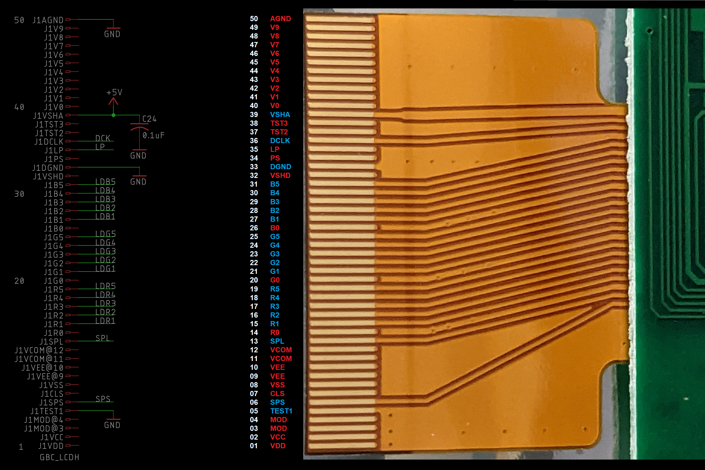
45 |
46 | ## Audio Amplifier
47 |
48 | The new audio circuit on the MGBC is powered by the LM4853, the same as my DMGC project. This TI chip is perfectly suited for the Game Boy - it has stereo inputs and headphone outputs, and mono speaker output. Makes it quite easy to implement without extra circuitry shenanigans.
49 |
50 | 
51 |
52 | - C18/C19 are DC blocking capacitors and RA1A/RA1B are current limiting resistors, so when the volume is turned all the way down, the S01 and S02 pins aren’t overloaded.
53 | - C52/C53 are DC blocking capacitors so only the AC audio signal passes to the amplifier.
54 | - The ratio of R30/R31 and R32/R33 set the amplification of the audio amp - increase R30 and R32 to decrease the output volume.
55 | - The audio gain has quite a large effect on the power draw and power quality of the system when using the speaker. I do not recommend using an amplification of greater than 0.2.
56 | - The shutdown pin should be tied to GND to allow the amp to work. The output on the headphones will sound really quiet and the speaker won't work if the chip is shutdown.
57 | - The headphone detect pin (HP_SWITCH) is connected to GND when the headphone jack is empty, and is pulled up to 5 V via R36 when headphones are inserted. This switches the output on the audio amplifier between the speakers and headphones. C51 is for debouncing the headphone detection.
58 | - C26/C27 are DC blocking capacitors so only the AC audio signal passes to the headphones.
59 | - The speaker output shouldn't need a DC blocking capacitor, as the LM4853 outputs to the speaker as a bridge tied load (BTL). However, I found that if a DC blocking capacitor is not included, a strange issue is possible in specific situations. There’s a very brief moment when plugging the headphones in where the right output channel is shorted to ground (ring and sleeve are connected inside the jack). When this happens, the right output DC blocking cap is connected to GND, and causes a large surge of current from the power supply to charge it up. In my testing, this sometimes would cause a brownout, causing the power supply to shut off. Therefore, I have included C8 for DC blocking.
60 | - Similarly, R22 and R23 are included to pull down the negative sides of the DC blocking capacitors C26 and C27 when headphones are not connected – without them, the outputs would be floating. This will prevent inrush current during headphone insertion, which I have seen cause issues with the LM4853 in the past.
61 |
62 | ## CPU Reset
63 |
64 | I’ve replaced the original PST9135N with a TPS3840DL35. These chips pull the /RESET pin on the CPU low when the voltage supply drops below 3.5 V (/RESET set to low turns off the CPU). The TPS3840DL35 does the same thing. The reason this chip is included is to hold the CPU off while powering down so no random instructions are made while the game is turning off.
65 |
66 | R3 and C17 introduces a time delay on the /RESET pin during start-up, to allow the rest of the power supplies to stabilize before letting the CPU operate. This is called a "power-on reset" circuit, and I used values that the original GBC schematic used. (The DMG, GBC, and GBA all use the same odd 18 ms time constant!)
67 |
68 | 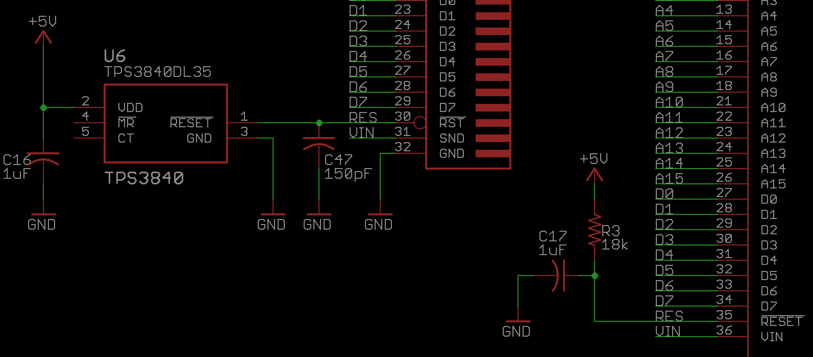
69 |
70 | ## Navigation Switch
71 |
72 | This takes place where the contrast wheel used to be. On the Q5 board, there are two capacitive touch sensors - one for changing brightness, one for changing the color palette. Instead of using the touch sensors in the MGBC, the navigation switch will toggle these inputs by connecting a series capacitance (C13 and C14) to ground to simulate a touch. This also has the benefit of not having to modify the driver board in any way, and instead just requiring soldered wires to the board where capacitive sensors were connected.
73 |
74 | 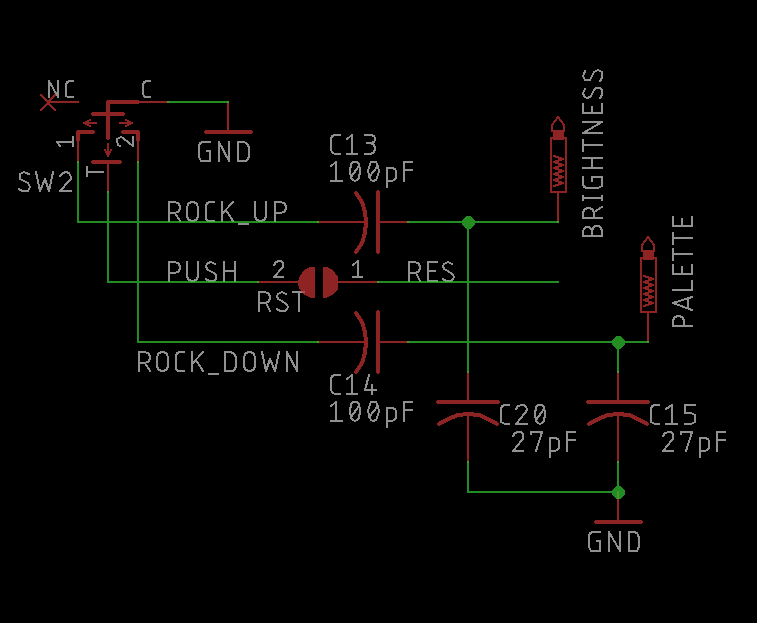
75 |
76 | C15 and C20 are provided to de-sensitize the touch sensors on the IPS kit, so that getting your fingers too close to the wires routed near the inside edge of the shell does not accidentally trigger a touch. Using the rocker switch doesn't *disable* the touch sensor, it just simulates a touch. So you can still accidentally trigger the touch sensors yourself.
77 |
78 | When wired properly, rocking up on the dial will toggle the brightness setting, rocking it down will toggle the color palette setting. Rocking up and holding it will toggle the battery level display on the screen, and rocking it down and holding it will toggle the pixel grid. Pushing in on the switch grounds the /RESET line on the CPU to act as a reset button, if the designated solder pads are bridged.
79 |
80 | ## OSD Pads
81 |
82 | There are six test points at the top of the MGBC for short wires to connect to the Q5 board. The Q5 board includes pads for the select, B, and A buttons for navigation in the OSD. And as previously mentioned - there's a battery pad, which is for measuring the battery life on the OSD, and two pads for brightness control and color palette swapping.
83 |
84 | 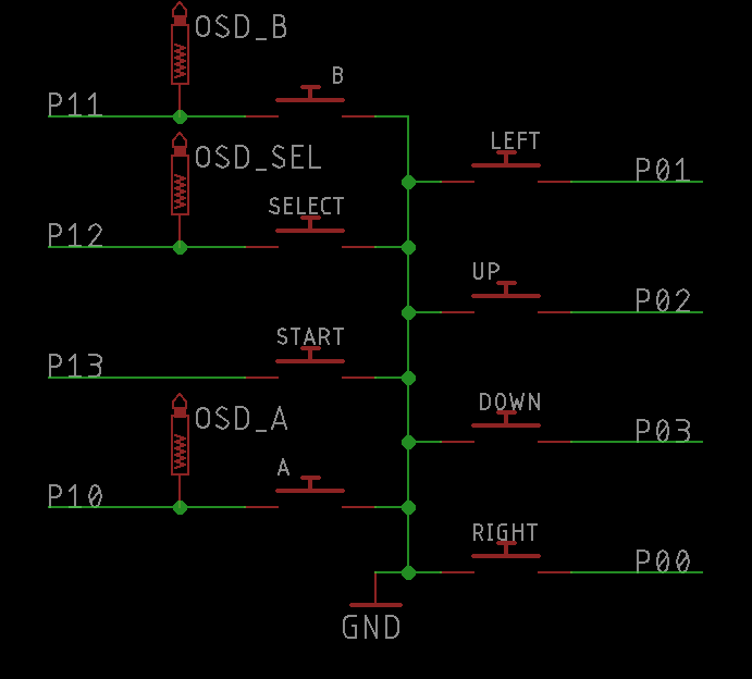
85 |
86 | # Resources
87 |
88 | - Pocket Mouse Power Board repo
89 | - GBC schematic
90 | - LM4853 datasheet
91 | - TPS3840 datasheet
92 |
93 | # License
94 |
This work is licensed under a Creative Commons Attribution-ShareAlike 4.0 International License. You are able to copy and redistribute the material in any medium or format, as well as remix, transform, or build upon the material for any purpose (even commercial) - but you **must** give appropriate credit, provide a link to the license, and indicate if any changes were made.
95 |
96 | ©MouseBiteLabs 2023
97 |
--------------------------------------------------------------------------------
/Technical/schematic.png:
--------------------------------------------------------------------------------
https://raw.githubusercontent.com/MouseBiteLabs/Game-Boy-Pocket-Color/e438e8a5643067cf37bb57570c9ef4bc98b809fd/Technical/schematic.png
--------------------------------------------------------------------------------
/Technical/schematic_v1-5_(OLD).png:
--------------------------------------------------------------------------------
https://raw.githubusercontent.com/MouseBiteLabs/Game-Boy-Pocket-Color/e438e8a5643067cf37bb57570c9ef4bc98b809fd/Technical/schematic_v1-5_(OLD).png
--------------------------------------------------------------------------------
/Technical/schematic_v1-6_(OLD).png:
--------------------------------------------------------------------------------
https://raw.githubusercontent.com/MouseBiteLabs/Game-Boy-Pocket-Color/e438e8a5643067cf37bb57570c9ef4bc98b809fd/Technical/schematic_v1-6_(OLD).png
--------------------------------------------------------------------------------
/audio_GBC.mp3:
--------------------------------------------------------------------------------
https://raw.githubusercontent.com/MouseBiteLabs/Game-Boy-Pocket-Color/e438e8a5643067cf37bb57570c9ef4bc98b809fd/audio_GBC.mp3
--------------------------------------------------------------------------------
/audio_MGBC.mp3:
--------------------------------------------------------------------------------
https://raw.githubusercontent.com/MouseBiteLabs/Game-Boy-Pocket-Color/e438e8a5643067cf37bb57570c9ef4bc98b809fd/audio_MGBC.mp3
--------------------------------------------------------------------------------
/previous_revs_BOM.csv:
--------------------------------------------------------------------------------
1 | Name Changes from v1.5 to v1.6,,,,,Cart link for v1.5 and earlier:,https://www.mouser.com/ProjectManager/ProjectDetail.aspx?AccessID=79af12f511
2 | LED1 >> D2,,,,,,
3 | ,,,,,,
4 | Parts not on v1.5 and earlier,,,,,,
5 | "Q1, C21",,,,,,
6 | ,,,,,,
7 | BOM Changes/Additions for v1.5 and earlier,,,,,,
8 | Reference Designators,Qty,Value/Part Number,Package,Description,Comment,Source
9 | C11,1,1uF,0603,Capacitor (MLCC),"Should be X5R (or better), at least 16V",https://www.mouser.com/ProductDetail/KEMET/C0603C105K3PACTU?qs=STjISULpmtalQKXy67%252B4Cg%3D%3D
10 | Q2,1,MMBT3904,SOT23,NPN BJT,,https://www.mouser.com/ProductDetail/Nexperia/MMBT3904VL?qs=cnAQGvEIVkKbCwIpHJoHxQ%3D%3D
11 | R4,1,200k,0603,Resistor,,https://www.mouser.com/ProductDetail/YAGEO/RC0603FR-10200KL?qs=x6vGwhDZZUbWpD4Ucl8tsQ%3D%3D
12 | R5,1,140k,0603,Resistor,,https://www.mouser.com/ProductDetail/YAGEO/RC0603FR-07140KL?qs=IuGqVx9wL0ITcCE98xJS3Q%3D%3D
13 | R8,1,100k,0603,Resistor,,https://www.mouser.com/ProductDetail/YAGEO/RC0603FR-07100KL?qs=e1ok2LiJcmaihem8Va5%2Fsw%3D%3D
14 |
--------------------------------------------------------------------------------