├── Init.m
├── imgs
├── image1.png
├── image2.png
├── image3.png
├── image4.png
├── image5.png
├── image6.png
├── image7.png
├── image8.png
├── image9.png
├── flyeval.png
├── flyveal2.png
├── image10.png
├── videocover.png
├── SimulinkSetting.png
├── SimulinkRunandCompile.png
└── SimulinkOutputDefinitions.png
├── MavLinkStruct.mat
├── MathModelDocEn.pdf
├── Multicopter_vPC.slx
├── SupportedVehicleTypes.docx
└── README.md
/Init.m:
--------------------------------------------------------------------------------
https://raw.githubusercontent.com/RflySim/CopterSim/HEAD/Init.m
--------------------------------------------------------------------------------
/imgs/image1.png:
--------------------------------------------------------------------------------
https://raw.githubusercontent.com/RflySim/CopterSim/HEAD/imgs/image1.png
--------------------------------------------------------------------------------
/imgs/image2.png:
--------------------------------------------------------------------------------
https://raw.githubusercontent.com/RflySim/CopterSim/HEAD/imgs/image2.png
--------------------------------------------------------------------------------
/imgs/image3.png:
--------------------------------------------------------------------------------
https://raw.githubusercontent.com/RflySim/CopterSim/HEAD/imgs/image3.png
--------------------------------------------------------------------------------
/imgs/image4.png:
--------------------------------------------------------------------------------
https://raw.githubusercontent.com/RflySim/CopterSim/HEAD/imgs/image4.png
--------------------------------------------------------------------------------
/imgs/image5.png:
--------------------------------------------------------------------------------
https://raw.githubusercontent.com/RflySim/CopterSim/HEAD/imgs/image5.png
--------------------------------------------------------------------------------
/imgs/image6.png:
--------------------------------------------------------------------------------
https://raw.githubusercontent.com/RflySim/CopterSim/HEAD/imgs/image6.png
--------------------------------------------------------------------------------
/imgs/image7.png:
--------------------------------------------------------------------------------
https://raw.githubusercontent.com/RflySim/CopterSim/HEAD/imgs/image7.png
--------------------------------------------------------------------------------
/imgs/image8.png:
--------------------------------------------------------------------------------
https://raw.githubusercontent.com/RflySim/CopterSim/HEAD/imgs/image8.png
--------------------------------------------------------------------------------
/imgs/image9.png:
--------------------------------------------------------------------------------
https://raw.githubusercontent.com/RflySim/CopterSim/HEAD/imgs/image9.png
--------------------------------------------------------------------------------
/MavLinkStruct.mat:
--------------------------------------------------------------------------------
https://raw.githubusercontent.com/RflySim/CopterSim/HEAD/MavLinkStruct.mat
--------------------------------------------------------------------------------
/imgs/flyeval.png:
--------------------------------------------------------------------------------
https://raw.githubusercontent.com/RflySim/CopterSim/HEAD/imgs/flyeval.png
--------------------------------------------------------------------------------
/imgs/flyveal2.png:
--------------------------------------------------------------------------------
https://raw.githubusercontent.com/RflySim/CopterSim/HEAD/imgs/flyveal2.png
--------------------------------------------------------------------------------
/imgs/image10.png:
--------------------------------------------------------------------------------
https://raw.githubusercontent.com/RflySim/CopterSim/HEAD/imgs/image10.png
--------------------------------------------------------------------------------
/MathModelDocEn.pdf:
--------------------------------------------------------------------------------
https://raw.githubusercontent.com/RflySim/CopterSim/HEAD/MathModelDocEn.pdf
--------------------------------------------------------------------------------
/Multicopter_vPC.slx:
--------------------------------------------------------------------------------
https://raw.githubusercontent.com/RflySim/CopterSim/HEAD/Multicopter_vPC.slx
--------------------------------------------------------------------------------
/imgs/videocover.png:
--------------------------------------------------------------------------------
https://raw.githubusercontent.com/RflySim/CopterSim/HEAD/imgs/videocover.png
--------------------------------------------------------------------------------
/imgs/SimulinkSetting.png:
--------------------------------------------------------------------------------
https://raw.githubusercontent.com/RflySim/CopterSim/HEAD/imgs/SimulinkSetting.png
--------------------------------------------------------------------------------
/SupportedVehicleTypes.docx:
--------------------------------------------------------------------------------
https://raw.githubusercontent.com/RflySim/CopterSim/HEAD/SupportedVehicleTypes.docx
--------------------------------------------------------------------------------
/imgs/SimulinkRunandCompile.png:
--------------------------------------------------------------------------------
https://raw.githubusercontent.com/RflySim/CopterSim/HEAD/imgs/SimulinkRunandCompile.png
--------------------------------------------------------------------------------
/imgs/SimulinkOutputDefinitions.png:
--------------------------------------------------------------------------------
https://raw.githubusercontent.com/RflySim/CopterSim/HEAD/imgs/SimulinkOutputDefinitions.png
--------------------------------------------------------------------------------
/README.md:
--------------------------------------------------------------------------------
1 | # CopterSim
2 | A high-fidelity simulation model developed in Simulink that compatible with different types of multicopters. The model can be used to develop control algorithms in Simulink. The simulation model includes sensor data outputs that can be used to generate code to performe hardware-in-the-loop simulations for autopilot systems like Pixhawk/PX4 or Ardupilot. The fault-injection function allows testing the safety and reliability of the control algorithms.
3 |
4 | ## Contact Info.
5 | Visit our Lab pages to contact us:
6 | http://rfly.buaa.edu.cn/index.html
7 |
8 | A video to present the hardware-in-the-loop simulation project based on this simulation model.
9 | [](https://youtu.be/GIb7JcGcXig)
10 |
11 |
12 |
13 | ## How to use the files.
14 | 1. Open "Multicopter_vPC.slx" file with Matlab 2017b and later. Noteworthy, the Aerospace Blockset is required for MATLAB.
15 | 2. Click the "Run" button to run the Simulink model.
16 | 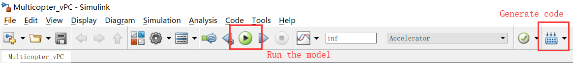
17 | 3. Click the "Compile" button to compile the model to C Code (Visual C++ 2015 or later is required).
18 | 4. Generate Code for LabVIEW for hardware-in-the-loop simulations. Configure the Simulink setting page according to the figure below.
19 | 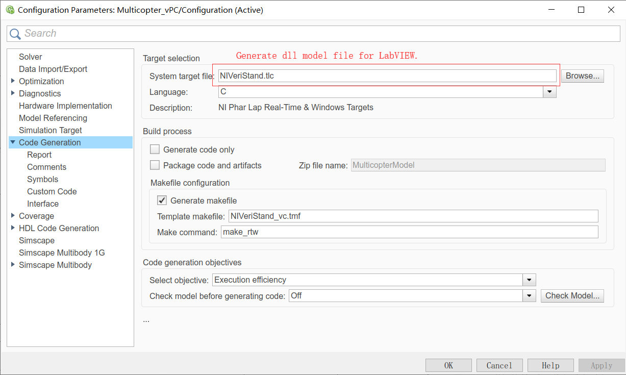
20 | 5. Generate code for embedded system. Change the above "System target file" option to "ert.tlc".
21 |
22 |
23 |
24 |
25 | ## File structure.
26 | imgs: images for this Readme.md Tutorial.
27 | Init.m: Initialization script automatically called before running the model File.
28 | MavLinkStruct.mat: the bus Structs for the output and input signals
29 | Multicopter_vPC.slx : the main Simulink model file.
30 | SupportedVehicleTypes.docx : supported vehicle types.
31 | MathModelDocEn.pdf : Mathematical derivation and simple modeling method for the simulatin model.
32 |
33 |
34 |
35 | ## Input and output Ports.
36 | inPWMs: input signal, ESC/motor control signal from the control system, eight-dimensional float vector, ranges from 0 to 1.
37 | Terrain: input signal, the current terrain height, one-dimensional float value, positive for the down direction, unit (m)
38 | MavHILSensor: output signal, bus struct, contains sensor data required by the Autopilot system like PX4/Ardupilot
39 | MavHILGPS: output signal, bus struct, contains GPS data required by the Autopilot system like PX4/Ardupilot
40 | MavVehileStateInfo: output signal, bus struct, contains true state of the vehicle for the vehicle software simulation in Simulink
41 | the detailed definition for the above output structs are presented below.
42 | 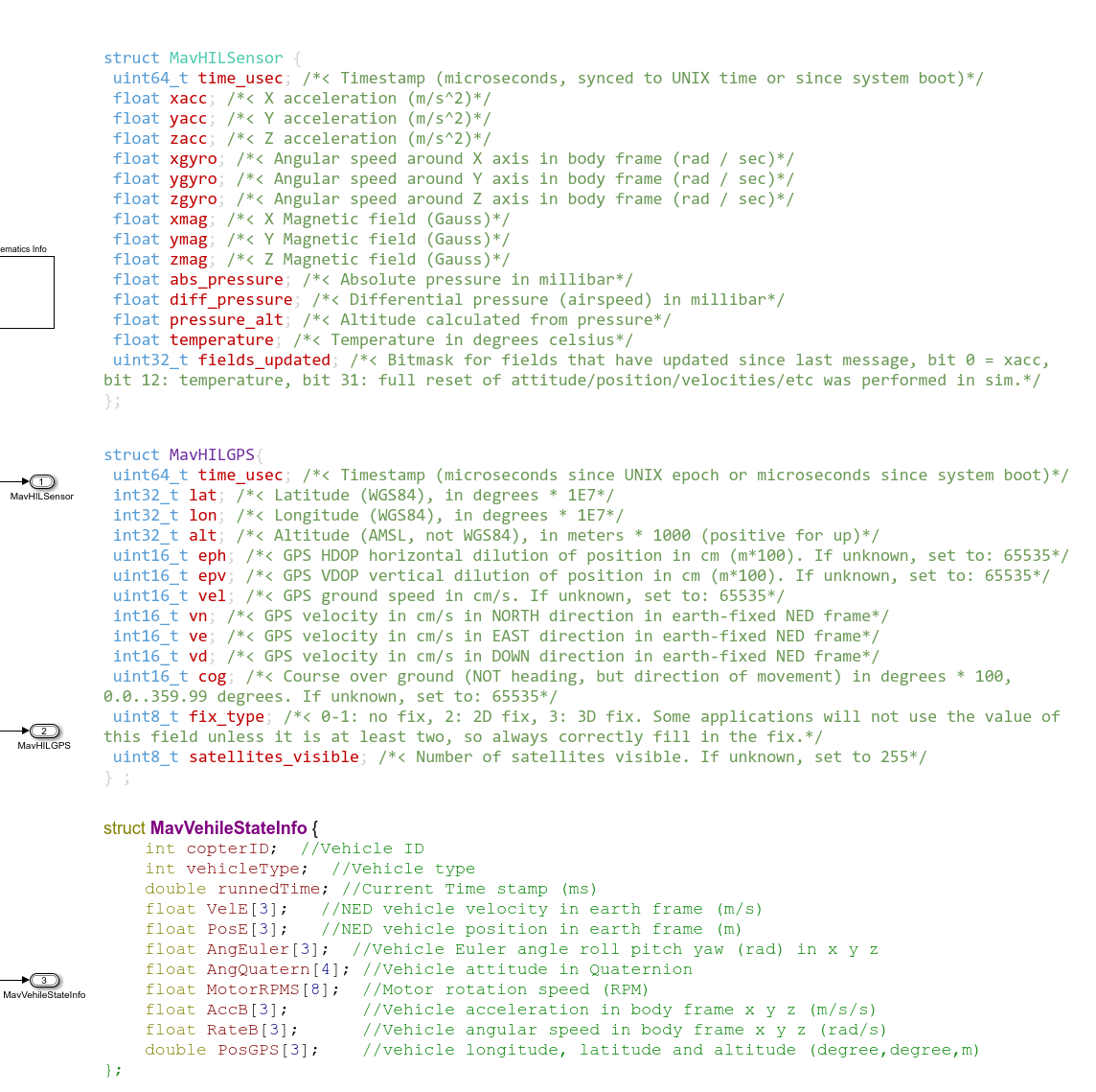
43 |
44 | ## Change vehicle types.
45 | The models cover all multicopter airframe for PX4 autopilot?http://dev.px4.io/en/airframes/airframe_reference.html
46 | Modify the parameter "ModelParam_uavType" in Init.m file to change the vehicle types.
47 | The supported vehicle types include:
48 | ModelParam_uavType = 1: Tricopter Y+
49 | 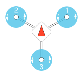
50 |
51 | ModelParam_uavType = 2: Tricopter Y-
52 | 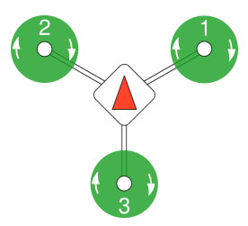
53 |
54 | ModelParam_uavType = 3: Quadrotor X
55 | 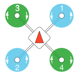
56 |
57 | ModelParam_uavType = 4: Quadrotor +
58 | 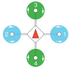
59 |
60 | ModelParam_uavType = 5: Hexarotor x
61 | 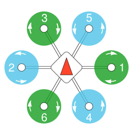
62 |
63 | ModelParam_uavType = 6: Hexarotor +
64 | 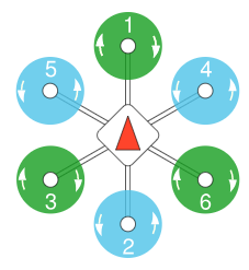
65 |
66 | ModelParam_uavType = 7: Hexarotor Coaxial
67 | 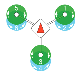
68 |
69 | ModelParam_uavType = 8: Octorotor x
70 | 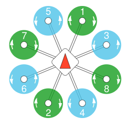
71 |
72 | ModelParam_uavType = 9: Octorotor +
73 | 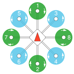
74 |
75 | ModelParam_uavType = 10: Octorotor Coaxial
76 | 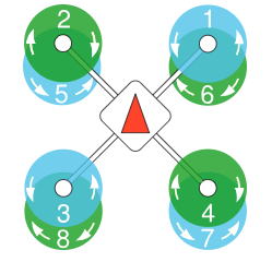
77 |
78 |
79 |
80 | ## An online toolbox to quickly obtain the model parameters
81 | https://flyeval.com
82 | [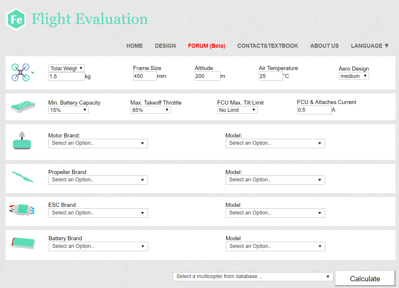](https://flyeval.com)
83 | [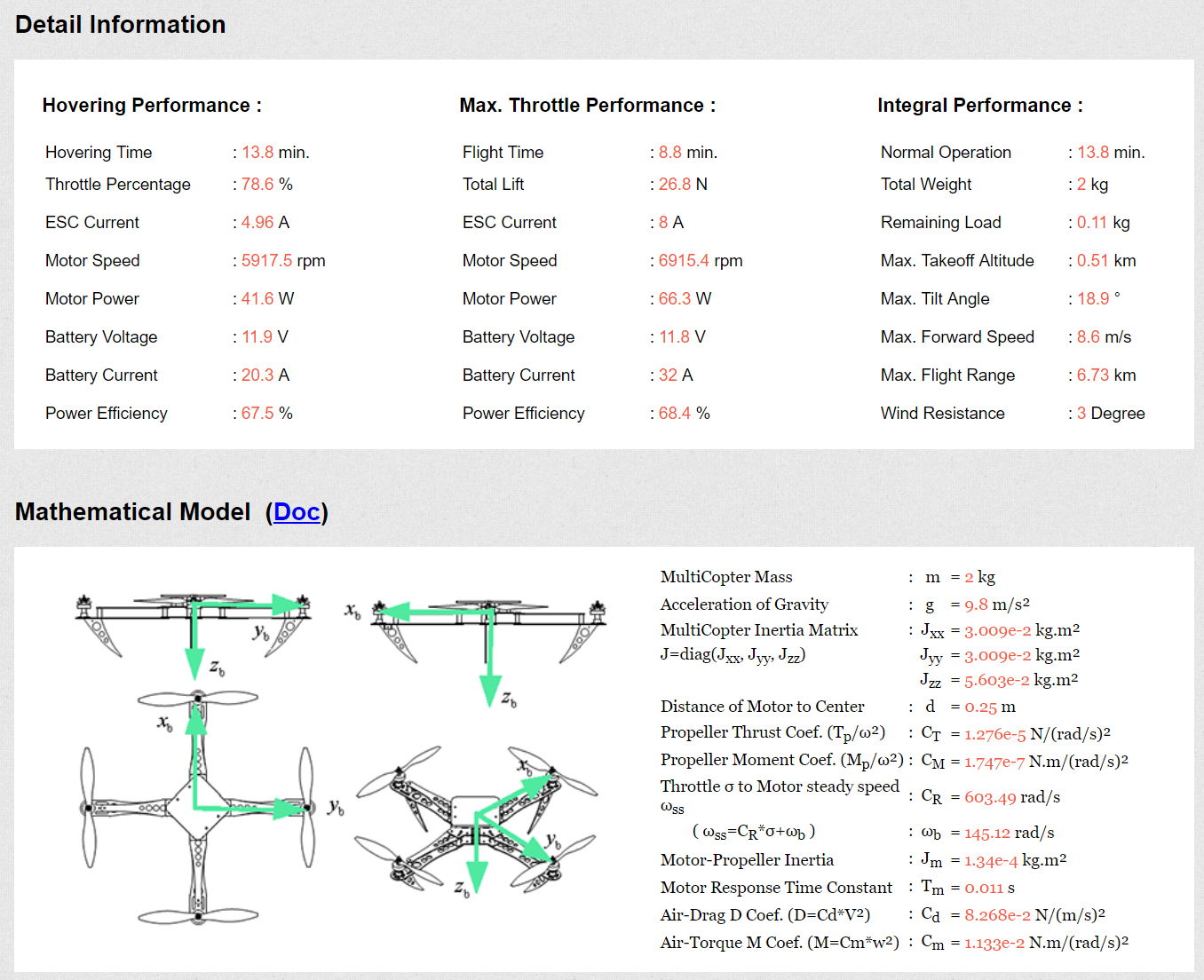](https://flyeval.com)
84 |
85 |
86 |
87 | ## Modify model parameters and inject fault during flight.
88 | Change the corresponding parameters in Init.m file
89 |
90 | load MavLinkStruct; % load the bus structs HILGPS MavLinkGPS MavLinkSensor MavVehileInfo
91 |
92 | %Initial condition
%set vehicle initial state.
93 | ModelInit_PosE = [0,0,0]; % Vehicle postion xyz in the NED earth frame (m)
94 | ModelInit_VelB = [0,0,0]; % Vehicle speed xyz in the NED earth frame (m/s)
95 | ModelInit_AngEuler = [0,0,0]; % Vehicle Euler angle xyz (roll,pitch,yaw) (rad)
96 | ModelInit_RateB = [0,0,0]; % Vehicle angular speed xyz (roll,pitch,yaw) in the body frame (rad/s)
97 | ModelInit_RPM = 0; %Initial motor speed (rad/s)
98 |
99 | %UAV model parameter
100 | ModelParam_uavMass = 1.4; %Mass of UAV(kg)
101 | ModelParam_uavJxx = 0.0241; % moment of inertia in body x axis
102 | ModelParam_uavJyy = 0.0239; % moment of inertia in body y axis
103 | ModelParam_uavJzz = 0.0386; % moment of inertia in body z axis
104 | %Moment of inertia matrix
105 | ModelParam_uavJ= [ModelParam_uavJxx,0,0;...
106 | 0,ModelParam_uavJyy,0;...
107 | 0,0,ModelParam_uavJzz];
108 | ModelParam_uavType = int8(3); %X-type quadrotor£¬refer to "SupportedVehicleTypes.docx" for specific definitions
109 | ModelParam_uavMotNumbs = int8(4); %Number of motors
110 | ModelParam_uavR = 0.225; %Body radius(m)
111 |
112 | ModelParam_motorCr = 1148; %Motor throttle-speed curve slope(rad/s)
113 | ModelParam_motorWb =-141.4; %Motor speed-throttle curve constant term(rad/s)
114 | ModelParam_motorT = 0.02; %Motor inertia time constant(s)
115 | ModelParam_motorJm = 0.0001287; %Moment of inertia of motor rotor + propeller(kg.m^2)
116 | %M=Cm*w^2
117 | ModelParam_rotorCm = 1.779e-07; %Rotor torque coefficient(kg.m^2)
118 | %T=Ct**w^2
119 | ModelParam_rotorCt = 1.105e-05; %Rotor thrust coefficient(kg.m^2)
120 | ModelParam_motorMinThr = 0.05; %Motor throttle dead zone(kg.m^2)
121 |
122 | ModelParam_uavCd = 0.055; %Damping coefficient(N/(m/s)^2)
123 | ModelParam_uavCCm = [0.0035 0.0039 0.0034]; %Damping moment coefficient vector(N/(m/s)^2)
124 | ModelParam_uavDearo = 0.12; %Vertical position difference of Aerodynamic center and gravity center(m)
125 |
126 | ModelParam_GlobalNoiseGainSwitch =0; %Noise level gain
127 |
128 | %Environment Parameter
129 | ModelParam_envGravityAcc = 9.8; %Gravity acceleration(m/s^2). not used.
130 | ModelParam_envLongitude = 116.259368300000; %longitude (degree)
131 | ModelParam_envLatitude = 40.1540302; %Latitude (degree)
132 | ModelParam_GPSLatLong = [ModelParam_envLatitude ModelParam_envLongitude]; %Latitude and longitude
133 | ModelParam_envAltitude = -41.5260009765625; %Reference height, down is positive
134 | ModelParam_BusSampleRate = 0.001; %Model sampling rate
135 |
136 | ModelParam_timeSampBaro = 0.01; % Barometer data sample time
137 | ModelParam_timeSampTurbWind = 0.01; % Atmospheric turbulence data sample time
138 | %%%ModelParam_BattModelEnable=int8(0);
139 | ModelParam_BattHoverMinutes=18; %time of endurance for the battery simulation
140 | ModelParam_BattHoverThr=0.609; % Vehilce hovering time
141 |
142 | %GPS Parameter
143 | ModelParam_GPSEphFinal=0.3; % GPS horizontal accuracy
144 | ModelParam_GPSEpvFinal=0.4; % GPS vertical accuracy
145 | ModelParam_GPSFix3DFix=3; % GPS fixed index
146 | ModelParam_GPSSatsVisible=10; % GPS number of satellites
147 |
148 | %Noise Parameter
149 | ModelParam_noisePowerAccel = [0.001,0.001,0.003];% accelerometer noise power xyz in Body frame
150 | ModelParam_noiseSampleTimeAccel = 0.001; % accelerometer noise sample time
151 | ModelParam_noisePowerOffGainAccel = 0.04; %accelerometer noise factor without motor vibration
152 | ModelParam_noisePowerOffGainAccelZ = 0.03; %accelerometer Z noise factor without motor vibration
153 | ModelParam_noisePowerOnGainAccel = 0.8; %accelerometer noise factor under motor vibration
154 | ModelParam_noisePowerOnGainAccelZ = 4.5; %accelerometer Z noise factor under motor vibration
155 | ModelParam_noisePowerGyro = [0.00001,0.00001,0.00001]; %gyroscope noise power xyz in Body frame
156 | ModelParam_noiseSampleTimeGyro = 0.001; % gyroscope noise sample time
157 | ModelParam_noisePowerOffGainGyro = 0.02; %accelerometer noise factor without motor vibration
158 | ModelParam_noisePowerOffGainGyroZ = 0.025; %accelerometer noise Z factor without motor vibration
159 | ModelParam_noisePowerOnGainGyro = 2; %accelerometer noise factor under motor vibration
160 | ModelParam_noisePowerOnGainGyroZ = 1; %accelerometer Z noise factor under motor vibration
161 |
162 | ModelParam_noisePowerMag = [0.00001,0.00001,0.00001];
163 | ModelParam_noiseSampleTimeMag = 0.01; %magnetometer sample time
164 | ModelParam_noisePowerOffGainMag = 0.02; %magnetometer noise gain without motor magnetic field effect
165 | ModelParam_noisePowerOffGainMagZ = 0.035;
166 | ModelParam_noisePowerOnGainMag = 0.025; %magnetometer noise gain under motor magnetic field effect
167 | ModelParam_noisePowerOnGainMagZ = 0.05;
168 | ModelParam_noisePowerIMU=0;%IMU noisePower
169 |
170 | ModelParam_noiseUpperGPS=0.5; %GPS noise upper limit (unit:m)
171 | ModelParam_noiseGPSSampTime=0.2;%GPS Sample time (5Hz)
172 |
173 | ModelParam_noiseUpperBaro=0; %barometer noise upper limit (unit: m)
174 | ModelParam_noiseBaroSampTime=0.5;%barometer noise sample time
175 | ModelParam_noiseBaroCoupleWithSpeed=0;% barometer disturbance factor caused by moving forward
176 |
177 | ModelParam_noiseUpperWindBodyRatio=0;% wind distrubance amplitude scale factor
178 | ModelParam_noiseWindSampTime=0.001;
179 |
180 |
181 | ModelParam_envAirDensity = 1.225; %ideal air density (not used)
182 | ModelParam_envDiffPressure = 0; % Differential pressure (airspeed) in millibar
183 | ModelParam_noiseTs = 0.001;
184 |
185 | %Failt Injection Test
186 | ModelFailEnable = boolean(0); %is enabling failt injection test
187 |
188 | %Battery fault simulation info.
189 | ModelFailBatt_isEnable = boolean(0); %is injecting battery fault?
190 | ModelFailBatt_isUseCustomHovTime = boolean(0); % is use time of endurance simulation?
191 | ModelFailBatt_CustomHovTime=15;%the time of endurance (unit min)
192 | ModelFailBatt_isPowOff = boolean(0);% is power off failure injected.
193 | ModelFailBatt_isLowVoltage = boolean(0); % is low voltage failure injected
194 | ModelFailBatt_remainVoltageRatio = 0.5; %remain voltage for low voltage failure injiection
195 | ModelFailBatt_islowCapacity = boolean(0); % is low capacility failure injected
196 | ModelFailBatt_remainCapacityRatio=0.2; %remain capacility for low capacility failure injection
197 |
198 |
199 | %Propeller Model Failed
200 | ModelFailProp_isEnable = boolean(1);% is injecting propeller failed
201 | ModelFailProp_PropEffRatioVec = ones(1,8);%health state of the eight propeller (0:totally failed,0.x: propller thrust ratio, 1:OK);
202 |
203 | %Payload failure injection
204 | ModelFailLoad_isEnable = boolean(0);%is Enabling payload failure
205 | ModelFailLoad_loadMassRatio = 0; %payload weight ratio for the vehicle weight (0 to 1)
206 | ModelFailLoad_isLoadFall = boolean(0); %is payload droped
207 | ModelFailLoad_isLoadShift = boolean(0); %is payload offset
208 | ModelFailLoad_LoadShiftXRatio = 0; %x-direction offset ration 0 to 1
209 | ModelFailLoad_LoadShiftYRatio = 0; %y-direction offset ration 0 to 1
210 | ModelFailLoad_LoadShiftZRatio = 0; %z-direction offset ration 0 to 1
211 | ModelFailLoad_isLoadLeak = boolean(0); %is payload slowly leaked
212 | ModelFailLoad_LoadLeakRatioRate = 0; %leak speed %/s
213 |
214 |
215 | %wind disturbance Failure
216 | ModelFailWind_isEnable = boolean(0);%is enabling wind disturbance
217 | ModelFailWind_isConstWind = boolean(0);%is constant wind disturbance
218 | ModelFailWind_ConstWindX = 0;%constant wind X-direction speed (m/s)
219 | ModelFailWind_ConstWindY = 0;%constant wind Y-direction speed(m/s)
220 | ModelFailWind_ConstWindZ = 0;%constant wind Z-direction speed(m/s)
221 | ModelFailWind_isGustWind = boolean(0);%is enabling Gust wind
222 | ModelFailWind_GustWindStrength =0;%gust wind stregth (m/s)
223 | ModelFailWind_GustWindFreq =0;%gust wind frequency (times/per minute)
224 | ModelFailWind_isTurbWind = boolean(0);% is enabling atmospheric turbulence
225 | ModelFailWind_TurbWindStrength =0;%turbulence strength
226 | ModelFailWind_isSheerWind = boolean(0);%is enabling sheer wind disturabance
227 | ModelFailWind_SheerWindStrength =0;%sheer wind strength
228 |
229 | ModelFailWind_TurbWindDirec=0;%turbulence wind yaw direction
230 | ModelFailWind_SheerWindDirec=0;%sheer wind yaw direction
231 |
232 |
233 |
234 |
--------------------------------------------------------------------------------