7 |
8 | The platform is mainly composed of three parts.
9 |
10 | 1. chassis module
11 |
12 |
13 |
14 |
15 |
16 | - Use Mecanum wheels for omnidirectional movement
17 |
18 | - Powered by the RoboMaster [M3508 P19 Brushless DC Gear Motor](https://store.dji.com/product/rm-m3508-p19-brushless-dc-gear-motor) and RoboMaster [C620 ESC](https://store.dji.com/product/rm-c620-brushless-dc-motor-speed-controller))
19 |
20 | - Use RoboMaster [Development Board](https://store.dji.com/product/rm-development-board-type-a?from=menu_products)[ Type A](https://store.dji.com/product/rm-development-board-type-a?from=menu_products) (STM32F427) as MCU
21 |
22 |
23 | 2. Gimbal module
24 |
25 |
26 |
27 |
28 |
29 |
30 | - Use 2-axis gimbal for two-DOF rotation movement
31 | - Provide the mechanism for supplying and launching 17mm TPU projectiles
32 | - Powered by RoboMaster [GM6020 Brushless Motor](https://store.dji.com/cn/product/rm-gm6020-brushless-dc-motor) (with the ESC) for gimbal movement
33 | - Powered by RoboMaster [M2006 P36 Brushless DC Gear Motor](https://store.dji.com/cn/product/rm-m2006-p36-brushless-motor) for projectile supply
34 | - Powered by [DJI Snail 2305 Racing Motor](https://store.dji.com/product/snail-racing-propulsion-system?from=menu_products) for projectile launching
35 | - Use RoboMaster [Development Board Type A](https://store.dji.com/product/rm-development-board-type-a?from=menu_products) (STM32F427) as MCU
36 |
37 |
38 | 3. Referee system module
39 |
40 |
41 |
42 |
43 |
44 |
45 | - An electronic penalty system that integrates computation, communication, and control features into different submodules and is used for robotic competitions only. Developers can acquire the information from specific software interface about the progress of the competition and the status of robots
46 | - The Referee System includes the onboard terminal installed on the robot, as well as the server and client software installed on the PC
47 | - Submodules installed on the robot consists of **Armor Module**,**Main Control Module**,**Speed Monitor Module**,**RFID Interaction Module** and **Power Management Module**
48 | - For more information about the referee system, please refer to "the Referee System Specification Manuel" under [Related Resources](en/resources).
49 |
50 | In addition, **DT7 Remote Controller** and smart Lipo 6s battery ([Matrice 100 TB47D Battery](https://store.dji.com/product/matrice-100-tb47d-battery?from=autocomplete&position=0) or [TB48D](https://store.dji.com/product/matrice-100-tb48d-battery)) with related charger are included in the accessories of the robot plateform.
51 |
52 | The platform accommodates an extensive variety of sensors and computing devices, customized to meet research needs easy for extended development. It provides sensor Installation holder compatible with different types of sensors including industrial mono-camera, Lidar, UWB locating kit, depth camera and so on. And the platform officially supported DJI Manifold 2 as the onboard computing device, but it is compatible with intel NUC, Nvidia Jetson TX1, TX2 or Xavier with certain type of carrier board.
53 |
54 | ## Hardware Parameters
55 | | Structure | |
56 | | :-------------------- | :-------------------- |
57 | | Overall size | 600 x 450 x 460 mm |
58 | | Weight (Including battery) | 16.6 kg |
59 | | **Performance** | |
60 | | Maximum forward Speed | 3 m/s |
61 | | Maximum Pan Speed | 2 m/s |
62 | | Gimbal Pitch axis rotating angle | -20° ~ 20° |
63 | | Gimbal Yaw axis rotating angle | -90° ~ 90° |
64 | | Maximum launching frequency | 10 projectiles per second |
65 | | Maximum launching speed | 25 m/s |
66 | | Remote Controller | 200 projetiles |
67 | | **Battery** | |
68 | | Model | DJI TB47D / DJI TB48D |
69 | | Type | LiPo 6s |
70 | | Voltage | 22.8v |
71 | | Battery capacity | 4500 mAH / 5700 mAH |
72 | | **Remote control** | |
73 | | Model | DJI DT7 |
74 | | Firmware upgrade | 2.4 GHz |
75 | | Charing port | Micro USB |
76 | | **Communicating port** | |
77 | | Port type | Micro USB |
78 | | Communication mode | STM32???? |
79 | | Baud rate | 921600 |
80 |
81 |
82 |
--------------------------------------------------------------------------------
/en/quick_start/quick_test.md:
--------------------------------------------------------------------------------
1 | # Quick Test
2 |
3 | > [!Warning]
4 | >
5 | >Before testing, Refer to [Software Dependency Configuration](en/quick_start/setup_on_manifold2?id=software-dependency-configuration) and [Roborts Download and Compile](en/quick_start/setup_on_manifold2?id=roborts-download-and-compile). Make sure software dependencies are installed, roborts packages are compiled successfully according to the guidelines before testing.
6 |
7 | ### Test in Simulator
8 |
9 | 1. Launch the script of Stage simulator, localization and motion planning modules
10 | ```bash
11 | roslaunch roborts_bringup roborts_stage.launch
12 | ```
13 |
14 | 2. Run behavior test node for simple decisions
15 | ```bash
16 | rosrun roborts_decision behavior_test_node
17 | ```
18 | Input different digital command like 1/2/3/4/5/6 and you can switch to perform different behaviors
19 |
20 | ### Test in Real World
21 |
22 | #### Step 1: Test Robot Driver
23 |
24 | 1. Launch the script of robot driver module
25 | ```
26 | roslaunch roborts_bringup base.launch
27 | ```
28 | Check the functionality to get information from MCU and control the robot through the command line tools
29 |
30 | > [!Tip]
31 | >
32 | >Robot driver module communicates with MCU through virtual serial, thus peripheral port mapping needs configuring correctly. Please refer to [Peripheral Port Mapping](en/quick_start/setup_on_manifold2?id=peripheral-port-mapping) for more information。
33 |
34 | #### Step 2: Test Simple Decisions
35 |
36 | 1. Launch the script of robot driver, static TF broadcaster, lidar, localization and motion planning modules
37 | ```bash
38 | roslaunch roborts_bringup roborts.launch
39 | ```
40 |
41 | 2. Run behavior test node for simple decisions
42 | ```bash
43 | rosrun roborts_decision behavior_test_node
44 | ```
45 | Input different digital command like 1/2/3/4/5/6 and you can switch to perform different behaviors
46 |
47 |
--------------------------------------------------------------------------------
/en/quick_start/setup_on_manifold2.md:
--------------------------------------------------------------------------------
1 | This chapter focuses on the deployment and application of RoboRTS on Manifold 2.
2 |
3 | > [!Tip]
4 | >
5 | > Manifold 2 is a microcomputer create by DJI for developers. The Manifold 2-G series is equipped with the NVIDIA Jetson TX2 module. The Manifold 2 is the Manifold 2-G series by default. This document also applies to the Nvidia Jetson TX2 Native Development Kit.
6 |
7 | ## Performance Configuration
8 |
9 | ### Turn on the maximum performance
10 |
11 | In Manifold 2, you can use NVPModel to allocate the cpu core number and the maximum frequency of cpu and gpu. Manifold 2 default mode only opens 4 `CPU` cores , to get maximum performance, you need to use the `nvpmodel` command to change the configuration.
12 |
13 | #### View and change mode
14 |
15 | ```bash
16 | sudo nvpmodel -q --verbose # View current mode
17 |
18 | sudo nvpmodel -m [mode] # For the introduction of each mode, please refer to the table in Appendix 1.
19 | sudo nvpmodel -m0 # Recommended configuration
20 | ```
21 | The mode corresponding to the number is as follows:
22 |
23 |
24 |
25 | | MODE | MODE NAME | DENVER 2 | FREQUENCY | ARM A57 | FREQUENCY | GPU FREQUENCY |
26 | | :--: | :------------: | :------: | :-------: | :-----: | :-------: | :-----------: |
27 | | 0 | Max-N | 2 | 2.0 GHz | 4 | 2.0 GHz | 1.30 Ghz |
28 | | 1 | Max-Q | 0 | | 4 | 1.2 GHz | 0.85 Ghz |
29 | | 2 | Max-P Core-All | 2 | 1.4 GHz | 4 | 1.4 GHz | 1.12 Ghz |
30 | | 3 | Max-P ARM | 0 | | 4 | 2.0 GHz | 1.12 Ghz |
31 | | 4 | Max-P Denver | 2 | 2.0 GHz | 0 | | 1.12 Ghz |
32 |
33 | #### Turn on the maximum clock frequency
34 |
35 | Manifold 2 will install this script in the Home directory. Run this script changing the clock frequency, mainly to maximize performance.
36 |
37 | ```bash
38 | sudo ./jetson_clocks.sh
39 | ```
40 |
41 | ### Network speed test and connection
42 |
43 | - Ethernet bandwidth and speed test on Manifold 2
44 |
45 | ``` bash
46 | sudo apt-get install iperf
47 | #start server
48 | sudo iperf -s
49 | #start client
50 | sudo iperf -c 192.168.1.xxx -i 5
51 | ```
52 |
53 | - WiFi test on Manifold 2
54 |
55 | - Turn off wlan0 energy saving mode
56 |
57 | ```bash
58 | iw dev wlan0 set power_save off #- to disable power save and reduce ping latency.
59 | iw dev wlan0 get power_save # will return current state.
60 |
61 | ```
62 |
63 | - View RSSI of WiFi
64 |
65 | ```bash
66 | watch -n 0.1 iw dev wlan0 link
67 | ```
68 |
69 | > [!Tip]
70 | >
71 | > Refer to the [Script](en/sdk_docs/roborts_bringup?id=script) section of the `roborts_bringup` module documentation to enable maximum performance and turn off wlan0 power-saving mode by booting the service after downloading and compiling the roborts packages.
72 |
73 |
74 | ## Peripheral Port Mapping
75 |
76 | According to the hardware interface (serial port, USB or ACM), configure the udev file in /etc/udev/rules.d to implement the device binding of the STM32 device virtual serial port and lidar:
77 |
78 | First connect to the virtual serial port of the STM32 device. lsusb can view the IDs of Vendor and Product, then create and configure the /etc/udev/rules.d/roborts.rules file.
79 |
80 | ```bash
81 | KERNEL=="ttyACM*", ATTRS{idVendor}=="0483", ATTRS{idProduct}=="5740", MODE:="0777", SYMLINK+="serial_sdk"
82 |
83 | ```
84 | The same applies to the laser scanner. Then reload and start the udev service, which may take effect after the device is re-plugged.
85 |
86 | ```bash
87 | sudo service udev reload
88 | sudo service udev restart
89 | ```
90 |
91 | It is a bit more troublesome to configure multiple cameras of the same model. Since the IDs of Vendor and Product are the same, you should check the specific characteristics of each camera.
92 |
93 | ```bash
94 | udevadm info --attribute-walk --name=/dev/video0
95 | ```
96 |
97 | Generally, you can use the serial port number as a property to distinguish each camera, for example:
98 |
99 | ```bash
100 | SUBSYSTEM=="usb", ATTR{serial}=="68974689267119892", ATTR{idVendor}=="1871", ATTR{idProduct}=="0101", SYMLINK+="camera0"
101 | SUBSYSTEM=="usb", ATTR{serial}=="12345698798725654", ATTR{idVendor}=="1871", ATTR{idProduct}=="0101", SYMLINK+="camera1"
102 | ```
103 |
104 | If it is a cheap camera, the serial port number may be the same, you can configure it according to the physical port of the connected HUB (KERNEL or KERNELS binding), for example:
105 |
106 | ```bash
107 | SUBSYSTEM=="usb", KERNEL=="2-3", ATTR{idVendor}=="1871", ATTR{idProduct}=="0101", SYMLINK+="camera0"
108 | SUBSYSTEM=="usb", KERNEL=="2-4", ATTR{idVendor}=="1871", ATTR{idProduct}=="0101", SYMLINK+="camera1"
109 | ```
110 |
111 | >[!Tip]
112 | >
113 | >You can refer to the [Script](en/sdk_docs/roborts_bringup?id=script) section of the `roborts_bringup` module documentation to execute the udev port mapping script after downloading and compiling the roborts packages.
114 |
115 |
116 |
117 | ## Software Dependency Configuration
118 |
119 | ### ROS (ros-kinetic-ros-base)
120 |
121 | Manifold 2 installs ROS Kinetic by default. If you use other platforms, you can install ROS by referring to the [Installation Guide](http://wiki.ros.org/kinetic/Installation/Ubuntu)
122 |
123 | > [!Note]
124 | >
125 | > Pay attention that whether to write `source /opt/ros/kinetic/setup.bash` into `.bashrc` or `.zshrc` to properly load ROS-related environment variables.
126 |
127 | Third-party dependencies required to install ROS, as well as other dependencies such as `SuiteSparse`, `Glog`, `Protobuf`
128 |
129 | ```bash
130 | sudo apt-get install -y ros-kinetic-opencv3 \
131 | ros-kinetic-cv-bridge \
132 | ros-kinetic-image-transport \
133 | ros-kinetic-stage-ros \
134 | ros-kinetic-map-server \
135 | ros-kinetic-laser-geometry \
136 | ros-kinetic-interactive-markers \
137 | ros-kinetic-tf \
138 | ros-kinetic-pcl-* \
139 | ros-kinetic-libg2o \
140 | ros-kinetic-rplidar-ros \
141 | ros-kinetic-rviz \
142 | protobuf-compiler \
143 | libprotobuf-dev \
144 | libsuitesparse-dev \
145 | libgoogle-glog-dev \
146 | ```
147 |
148 | ### Other recommended software
149 |
150 | - git
151 | - cmake
152 | - vim
153 | - terminator
154 | - htop
155 |
156 | ## RoboRTS Download and Compile
157 |
158 |
159 | ```bash
160 | # Create a workspace folder
161 | mkdir -p roborts_ws/src
162 | # Switch to the src directory
163 | cd roborts_ws/src
164 | # Download RoboRTS source code
165 | git clone https://github.com/RoboMaster/RoboRTS
166 | # Compile source code
167 | cd ..
168 | catkin_make
169 | # Load environment variables
170 | source devel/setup.bash
171 | ```
172 |
173 | > [!Note]
174 | >
175 | > If you use `zsh`, be careful to source `setup.zsh` instead of `setup.bash`.
176 |
--------------------------------------------------------------------------------
/en/resources.md:
--------------------------------------------------------------------------------
1 | # Documents
2 |
3 | ICRA 2019 RoboMaster AI Challenge documents
4 |
5 | ## Rules Manual V1.0
6 |
7 | [ICRA 2019 RoboMaster AI Challenge Rules Manual V1.0.pdf](https://rm-static.djicdn.com/tem/19806/ICRA%202019%20RoboMaster%20AI%20Challenge%20Rules%20Manual%20V1.0.pdf)
8 |
9 | ## AI Robot User Manual V1.0
10 |
11 | [ICRA 2019 DJI RoboMaster AI Challenge AI Robot User Manual V1.0.pdf](https://rm-static.djicdn.com/tem/19806/ICRA%202019%20DJI%20RoboMaster%20AI%20Challenge%20AI%20Robot%20User%20Manual%20V1.0.pdf)
12 |
13 |
14 | ## Referee System Specification Manual V1.0
15 |
16 | [ICRA 2019 RoboMaster AI Challenge Referee System Specification Manual V1.0.pdf](https://rm-static.djicdn.com/tem/19806/ICRA%202019%20RoboMaster%20AI%20Challenge%20Referee%20System%20Specification%20Manual%20V1.0.pdf)
17 |
18 | ## RoboMaster AI Robot Mechanism drawings
19 |
20 | ### STEP
21 |
22 | [Mechanism drawings STEP](https://rm-static.djicdn.com/documents/19806/4df8649b3596f1548056917303346609.STEP)
23 |
24 | ### SolidWorks
25 |
26 | (SolidWorks 2016 or higher version)
27 |
28 | [Mechanism drawings Solidworks](https://rm-static.djicdn.com/documents/19806/232fed8050cfe1548739880652461892.SLDPRT)
29 |
30 | ### Creo
31 | (Creo 3 or higher version)
32 |
33 | [Mechanism drawings Creo](https://rm-static.djicdn.com/documents/19806/a96a1cc07664b1548738962638883052.1)
34 |
35 | ## RoboMaster AI Robot Open Source Code Repository
36 | [RoboMaster AI Robot Embedded MCU(STM32)](https://github.com/RoboMaster/RoboRTS-Firmware)
37 |
38 | [RoboMaster AI Robot Onboard PC(ROS)](https://github.com/RoboMaster/RoboRTS)
--------------------------------------------------------------------------------
/en/roborts.md:
--------------------------------------------------------------------------------
1 |
RoboMaster 2019 AI Robot Platform
2 |
3 | 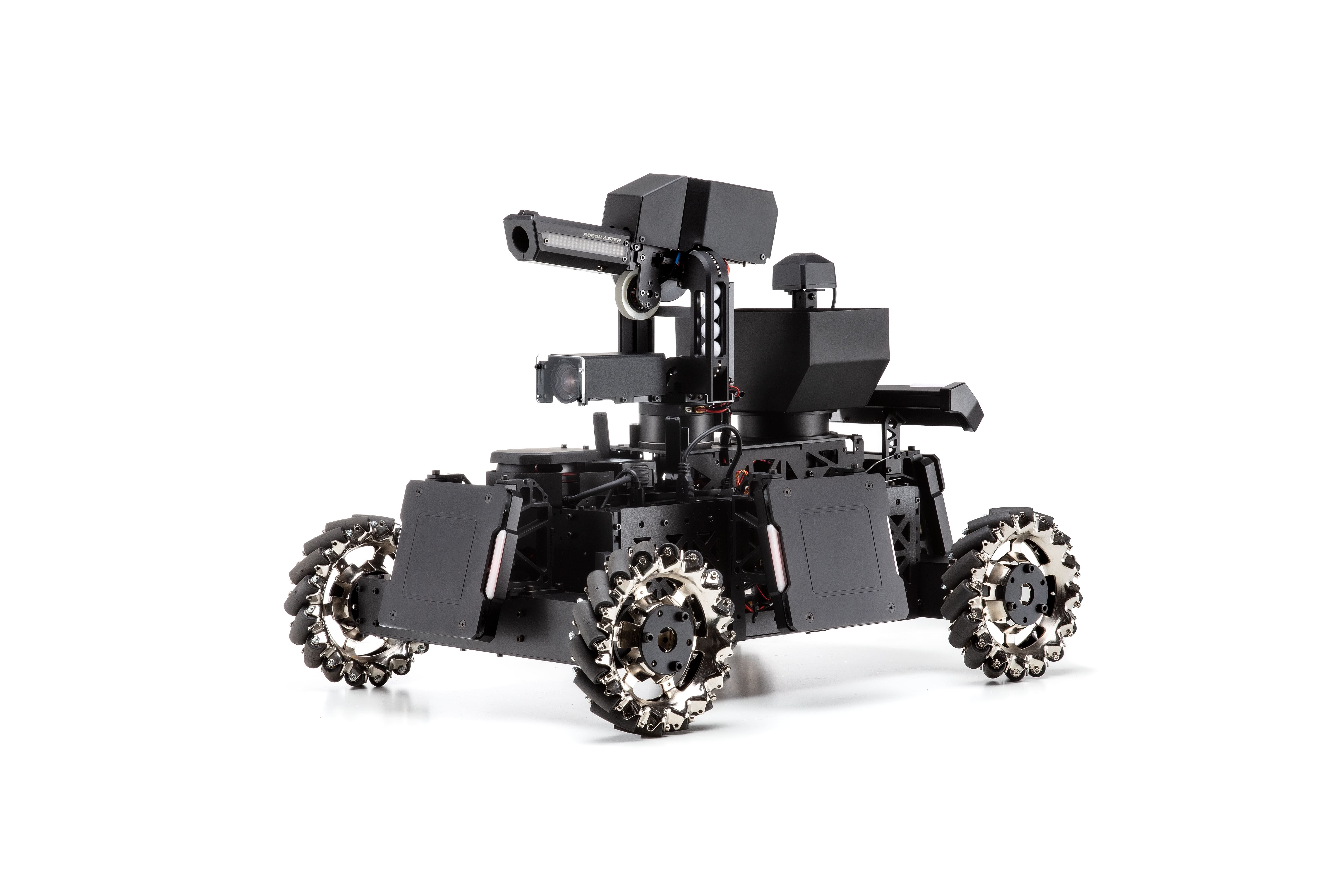
4 | **RoboMaster 2019 AI Robot Platform** is a universal mobile robot platform for [**ICRA 2019 RoboMaster AI Challenge**](https://www.icra2019.org/competitions/dji-robomaster-ai-challenge)**.** It is an Open Source Platform for not only mechanical design, but software framework for real-time embedded system based on STM32 series and onboard RoboRTS framework for advanced robotic algorithms fully supported in ROS with community driven as well as platform-customized code and examples.
5 |
--------------------------------------------------------------------------------
/en/sdk_docs/_sidebar.md:
--------------------------------------------------------------------------------
1 |
2 | * [Back](en/)
3 | * [architecture](en/sdk_docs/architecture.md)
4 | * [roborts_base](en/sdk_docs/roborts_base.md)
5 | * [roborts_camera](en/sdk_docs/roborts_camera.md)
6 | * [roborts_detection](en/sdk_docs/roborts_detection.md)
7 | * [roborts_localization](en/sdk_docs/roborts_localization.md)
8 | * [roborts_decision](en/sdk_docs/roborts_decision.md)
9 | * roborts_planning
10 | * [global path planner](en/sdk_docs/roborts_planning_global_planner.md)
11 | * [local trajecotry planner](en/sdk_docs/roborts_planning_local_planner.md)
12 | * [roborts_bringup](en/sdk_docs/roborts_bringup.md)
13 |
14 |
15 |
16 |
--------------------------------------------------------------------------------
/en/sdk_docs/architecture.md:
--------------------------------------------------------------------------------
1 | # Overall Architecture
2 |
3 | ## Architecture and Module Introduction
4 | The overall system is structured with the loop of `sensor->perception->decision->planning->control->executor`, and the different modules are maintained in the form of ROS Package. The module and its data flow are shown in the figure below.
5 | 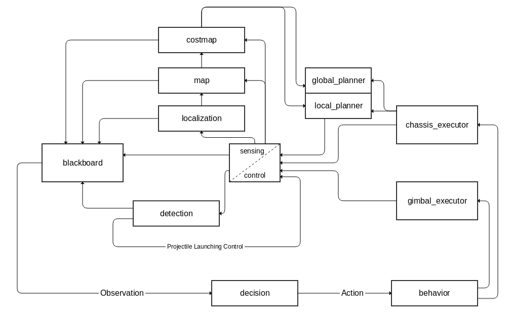
6 |
7 | ### Sensors, Controllers and Executers
8 |
9 | - The central module integrates sensor modules (lidar, camera, IMU, etc.), embedded control platform (executing real-time tasks such as closed-loop control and data acquisition and pre-processing) and actuators (motors, etc.), and is responsible for sensing and control. The ROS Package for the embedded SDK is [roborts_base] (en/sdk_docs/roborts_base); for the camera is [roborts_camera](en/sdk_docs/roborts_camera). The system also includes the ROS packages for the related sensor drivers.
10 |
11 | ### Perception
12 |
13 | Perception includes robot localization, map maintenance and representation, target detection and tracking, etc.
14 |
15 | - localization module is responsible for robot localization. See [roborts_localization](en/sdk_docs/roborts_localization) for details.
16 |
17 | - The map module is responsible for robot map maintenance, currently using ROS open source package [map_server](http://wiki.ros.org/map_server)
18 |
19 | - The costmap module is responsible for the representation of the costmap. It integrates the static map layer, the obstacle layer and the inflation layer. It is mainly used in the motion planning part. Please see roborts_costmap for details. In the subsequent plans, this module will be updated to feature map module, not only for planning.
20 |
21 | - The detection module is responsible for target detection and tracking. For details, see [roborts_detection](en/sdk_docs/roborts_detection). Currently, this module integrates the enemy detection and the projectile controller. Since the frame rate requirement is relatively high, the current detection and control are coupled, which will be decoupled later, putting the gimbal planner for tracking the target into the gimbal_executor.
22 |
23 | ### Task Scheduling and Decision Making
24 |
25 | The task scheduling and decision making part includes the interface of the perception scheduler as input and the plan execution scheduler as output , and the core framework of the decision-making.
26 | - The decision module is a robotic decision-making framework, and the Behavior Tree is officially provided. The blackboard module schedules the perception task acquisition information of various modules and the game information of the referee system. The behavior module integrates various actions or behaviors of the discrete action space. For details, see [roborts_decision](en/sdk_docs/roborts_decision)
27 |
28 | - The executor module is a dependency of the behavior module, which contains the delegation interface of the chassis and the gimbal of different abstraction levels (e.g. scheduling the chassis to execute the result of the motion planning). See roborts_decision/executor for details.
29 |
30 | ### Motion Planning
31 |
32 | The motion planning part is the motion planning function module, which is scheduled and delegated by the chassis_executor module in the decision part, completed in the roborts_planning part. See roborts_planning for details.
33 |
34 | - The global_planner module is responsible for the global path planning of the robot. See [roborts_planning/global_planner](en/sdk_docs/roborts_planning_global_planner) for details. It depends on roborts_costmap
35 |
36 | - The local_planner module is responsible for the local trajectory planning of the robot. See [roborts_planning/local_planner](en/sdk_docs/roborts_planning_local_planner) for details. It depends on roborts_costmap
37 |
38 |
39 | ## ROS Package Introduction
40 |
41 | | Package | function | internal dependency |
42 | | :--: | :------------: | :------: |
43 | | roborts | Meta-package | - |
44 | | roborts_base | Embedded communication interface | roborts_msgs |
45 | | roborts_camera | camera driver | roborts_common |
46 | | roborts_common | common dependency | - |
47 | | roborts_decision | robot decision package | roborts_common roborts_msgs roborts_costmap |
48 | | roborts_detection | computer vision detection algorithm package | roborts_msgs roborts_common roborts_camera |
49 | | roborts_localization | robot localization algorithm package | - |
50 | | roborts_costmap | costmap-related package | roborts_common |
51 | | roborts_msgs | custom message definition package | - |
52 | | roborts_planning | motion planning algorithm package | roborts_common roborts_msgs roborts_costmap |
53 | | roborts_bringup | launch package | roborts_base roborts_common roborts_localization roborts_costmap roborts_msgs roborts_planning |
54 | | roborts_tracking | computer vision tracking algorithm package | roborts_msgs |
55 |
--------------------------------------------------------------------------------
/en/sdk_docs/roborts_base.md:
--------------------------------------------------------------------------------
1 | # Robot Driver Module
2 |
3 | ## Module introduction
4 |
5 | The robot Driver Module is a bridge between the underlying embedded control board to the upper onboard computer,through the virtual serial port, the data type of bidirectional transmission is defined based on a common set of protocols, thereby completing the task of data mutual transmission.
6 |
7 | In computing device,`roborts_base `has a ROS interface which receives data sent by the underlying embedded control board and sends data to complete mode switching and motion control of the robot.
8 |
9 | `roborts_base`depends on the relevant message types defined in`roborts_msgs`.
10 |
11 | The module file directory is as follows
12 | ```bash
13 | roborts_base
14 | ├── CMakeLists.txt
15 | ├── cmake_module
16 | │ └── FindGlog.cmake
17 | ├── chassis #Chassis module ROS interface package
18 | │ ├── chassis.cpp
19 | │ └── chassis.h
20 | ├── gimbal #Gimbal module ROS interface package
21 | │ ├── gimbal.cpp
22 | │ └── gimbal.h
23 | ├── config
24 | │ └── roborts_base_parameter.yaml #Parameter configuration file
25 | ├── roborts_base_config.h #Parameter reading class
26 | ├── roborts_base_node.cpp #Core node Main function
27 | ├── ros_dep.h #Includes header files for all protocols corresponding to ROS messages
28 | ├── roborts_sdk
29 | │ ├── ...
30 | └── package.xml
31 | ```
32 | The Original protocol SDK in the roborts_sdk file,without any ROS dependencies, as follows
33 | ```bash
34 | ├── roborts_sdk
35 | │ ├── hardware #Hardware layer to raw data transmission
36 | │ │ ├── hardware_interface.h #Hardware layer base class
37 | │ │ ├── serial_device.cpp #Serial device implementation
38 | │ │ └── serial_device.h
39 | │ ├── protocol #Protocol layer to unpack and pack the message
40 | │ │ ├── protocol.cpp #Protocol layer
41 | │ │ ├── protocol_define.h #Protocol message type definition header file
42 | │ │ └── protocol.h
43 | │ ├── dispatch #The dispatch layer to dispatch message
44 | │ │ ├── dispatch.h #Dispatch layer
45 | │ │ ├── execution.cpp #Dispatch layer execution
46 | │ │ ├── execution.h
47 | │ │ ├── handle.cpp #roborts_sdk three-layer external interface
48 | │ │ └── handle.h
49 | │ ├── sdk.h #roborts_sdk external document
50 | │ ├── test
51 | │ │ └── sdk_test.cpp #Protocol test file
52 | │ └── utilities
53 | │ ├── circular_buffer.h #Ring buffer pool
54 | │ ├── crc.h #crc check file
55 | │ ├── log.h #Log file
56 | │ └── memory_pool.h #Memory pool
57 | ```
58 |
59 | >[!Note]
60 | >For details of the agreement, please refer to `RoboMaster AI Robot communication protocol document(TODO)`.
61 |
62 |
63 | In the core running node`roborts_base_node` of the module,After the objects of the required modules (such as the chassis and the gimbal) are created and initialized, the communication task can be performed normally.
64 |
65 | Its ROS node is shown as follows:
66 |
67 | 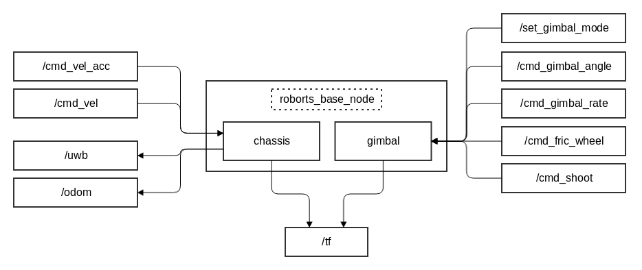
68 |
69 | ### Chassis Module
70 |
71 | #### Input
72 |
73 | * /cmd_vel ([geomtry_msgs/Twist]())
74 |
75 | Chassis speed control, In the next control cycle, the chassis is moving at a constant speed.
76 |
77 | * /cmd_vel_acc ([roborts_msgs/TwistAccel]())
78 |
79 | Chassis speed and acceleration control,During the next control cycle, the chassis performs a uniform acceleration motion at an initial given speed.
80 |
81 |
82 | #### Output
83 |
84 | * /odom ([nav_msgs/Odometry]())
85 |
86 | Chassis odometry information
87 |
88 | * /uwb ([geometry_msgs/PoseStamped]())
89 |
90 | Pose information of the chassis in the UWB coordinate system
91 |
92 | * /tf ([tf/tfMessage](http://docs.ros.org/api/tf/html/msg/tfMessage.html))
93 |
94 | From base_link->odom
95 |
96 |
97 | ### Gimbal Module
98 |
99 | #### Input
100 |
101 | * /cmd_gimbal_angle ([roborts_msgs/GimbalAngle]())
102 |
103 | Control of the angle of the gimba. Judging whether it is absolute angle control or relative angle control according to the relative angle mark
104 |
105 | * /cmd_gimbal_rate ([roborts_msgs/GimbalRate]())
106 |
107 | [**deprecated**] Gimbal rate control
108 |
109 | * /set_gimbal_mode ([roborts_msgs/GimbalMode]())
110 |
111 | Set the mode of the gimbal
112 |
113 | * /cmd_fric_wheel ([roborts_msgs/FricWhl]())
114 |
115 | Open and close the friction wheel (to be opened to launch speed control)
116 |
117 | * /cmd_shoot ([roborts_msgs/ShootCmd]())
118 |
119 | Control instructions for projectile launch (including launch mode, frequency and number)
120 |
121 | #### Output
122 |
123 | * /tf ([tf/tfMessage](http://docs.ros.org/api/tf/html/msg/tfMessage.html))
124 |
125 | From base_link->gimbal
126 |
127 | ### Related Parameters
128 |
129 | * serial_path(`string`, Defaults: "/dev/serial_sdk")
130 |
131 | Serial port path name,The default value is "/dev/serial_sdk" set by udev rules
132 |
133 | ## Compile and Run
134 |
135 | ### Compile
136 |
137 | Compile in the ROS workspace
138 |
139 | ```shell
140 | catkin_make -j4 roborts_base_node
141 | ```
142 |
143 | ### Run
144 |
145 | Execute the roborts_base_node
146 |
147 | ```shell
148 | rosrun roborts_base roborts_base_node
149 | ```
150 |
151 | Or start the relevant launch file
152 |
153 | ```shell
154 | roslaunch roborts_bringup base.launch
155 | ```
156 |
157 |
158 |
--------------------------------------------------------------------------------
/en/sdk_docs/roborts_bringup.md:
--------------------------------------------------------------------------------
1 | # Bringup Module
2 |
3 | ## Module Introduction
4 |
5 | The bringup module mainly includes basic configuration files and startup scripts in the roborts_bringup Package. The module file directory is as follows.
6 | ```bash
7 | roborts_bringup
8 | ├── CMakeLists.txt
9 | ├── launch #Launch startup script
10 | │ ├── base.launch #Robot driver script
11 | │ ├── roborts.launch #Functional script in the actual scene
12 | │ ├── roborts_stage.launch #Functional script in the stage simulation
13 | │ ├── mapping.launch #Mapping script in the actual scene
14 | │ ├── mapping_stage.launch #Mapping script in the stage simulation
15 | │ ├── slam_gmapping.xml #gmapping node script
16 | │ └── static_tf.launch #Static coordinate transformation script
17 | ├── maps #Map profile
18 | │ ├── icra2018.pgm
19 | │ ├── icra2018.yaml
20 | │ ├── icra2019.pgm
21 | │ └── icra2019.yaml
22 | ├── package.xml
23 | ├── rviz #rviz configuration file
24 | │ ├── mapping.rviz
25 | │ ├── roborts.rviz
26 | │ └── teb_test.rviz
27 | ├── scripts
28 | │ ├── udev #udev port mapping script
29 | │ │ ├── create_udev_rules.sh
30 | │ │ ├── delete_udev_rules.sh
31 | │ │ └── roborts.rules
32 | │ └── upstart #startup script
33 | │ ├── create_upstart_service.sh
34 | │ ├── delete_upstart_service.sh
35 | │ ├── jetson_clocks.sh
36 | │ ├── max-performance.service
37 | │ ├── max_performance.sh
38 | │ ├── roborts.service
39 | │ └── roborts-start.sh
40 | └── worlds #stage configuration file
41 | ├── icra2018.world
42 | └── icra2019.world
43 |
44 | ```
45 |
46 | ## Script
47 |
48 | Execute the script to add udev mapping rules:
49 |
50 | ```shell
51 | ./create_udev_rules.sh
52 | ```
53 |
54 | Execute the script to delete udev mapping rules:
55 | ```shell
56 | ./delete_udev_rules.sh
57 | ```
58 |
59 | The udev rule script is described in the `roborts.rules` file. According to the peripherals you need, you can add and modify it flexibly.
60 |
61 | In Manifold2, execute the script to add a startup service:
62 |
63 | ```shell
64 | ./create_upstart_service.sh
65 | ```
66 | Execute the script to delete the startup service:
67 |
68 | ```shell
69 | ./delete_upstart_service.sh
70 | ```
71 |
72 | The startup service includes
73 |
74 | - To execute the jetson_clock.sh script with the nvpmodel command to maximize performance.
75 |
76 | - Start the roborts.service service and execute the roborts-start.sh script to run the ros launch script.
77 |
78 | Users can modify the required script files and service files to customize the startup service according to their needs.
79 |
80 | ## Test and Run
81 |
82 | In the actual scenario, run the robot driver script
83 |
84 | ```shell
85 | roslaunch roborts_bringup base.launch
86 | ```
87 |
88 | In the actual scenario, execute the script for functional nodes in addition to the decision and scheduling module.
89 |
90 | ```shell
91 | roslaunch roborts_bringup roborts.launch
92 | ```
93 |
94 | In the stage simulation environment,execute the script for functional nodes in addition to the decision and scheduling module.
95 |
96 | ```shell
97 | roslaunch roborts_bringup roborts_stage.launch
98 | ```
99 |
100 | In the actual scenario, execute the test script for gmapping
101 |
102 | ```shell
103 | roslaunch roborts_bringup mapping.launch
104 | ```
105 |
106 | In the stage simulation environment, execute the test script for gmapping
107 |
108 | ```shell
109 | roslaunch roborts_bringup mapping_stage.launch
110 | ```
111 |
112 | > [!Note]
113 | >
114 | > Pay attention, all launch scripts that are applied in the actual scenario will not launch the rviz node for visualization by default.
115 |
--------------------------------------------------------------------------------
/en/sdk_docs/roborts_camera.md:
--------------------------------------------------------------------------------
1 | # Camera driver module
2 |
3 | ## Module Introduction
4 |
5 | The camera driver module encapsulates common camera drivers and publishes image data and camera parameters via ROS `image_transport`.
6 |
7 | The camera module is located in the roborts_camera Package and depends on the abstract factory pattern and parameter reading in the roborts_common Package. The module file directory is as follows
8 |
9 | ```bash
10 | roborts_camera
11 | ├── CMakeLists.txt
12 | ├── package.xml
13 | ├── cmake_module
14 | │ └── FindProtoBuf.cmake
15 | ├── camera_base.h #Camera abstract
16 | ├── camera_node.cpp #Camera core running node and Main function
17 | ├── camera_node.h
18 | ├── camera_param.cpp #Camera parameter reading
19 | ├── camera_param.h
20 | ├── config
21 | │ └── camera_param.prototxt #Camera parameter profile
22 | ├── proto
23 | │ ├── camera_param.pb.cc
24 | │ ├── camera_param.pb.h
25 | │ └── camera_param.proto #Camera parameter definition file
26 | ├── test
27 | │ └── image_capture.cpp #Camera test node for image capture
28 | └── uvc
29 | ├── CMakeLists.txt
30 | ├── uvc_driver.cpp #uvc camera
31 | └── uvc_driver.h
32 | ```
33 |
34 | The camera runs the node`roborts_camera_node`, which automatically dispatches the camera to publish image data by reading the configuration parameters of one or more cameras.
35 |
36 | ### Related Parameters
37 | The parameters are defined in `proto/camera_param.proto`. For the configuration of the parameters, see `config/camera_param.prototxt`which accepts multiple camera configurations. Single camera parameters include
38 |
39 | * camera_name (`string`)
40 |
41 | Camera name, namespace used to post camera messages
42 |
43 | * camera_type (`string`)
44 |
45 | Camera type, used to register and instantiate key values of camera objects in abstract factory mode, such as uvc camera as "uvc"
46 |
47 | * camera_path (`string`)
48 |
49 | Camera path, used to open the camera port path name
50 |
51 | * camera_matrix (`double[]`)
52 |
53 | Camera internal reference matrix, generally 3X3
54 |
55 | * camera_distortion (`double[]`)
56 |
57 | Camera distortion matrix
58 |
59 | * fps (`uint32`)
60 |
61 | Camera frame rate(Unit frame per second)
62 |
63 | * resolution
64 |
65 | * width (`uint32`)
66 |
67 | Resolution width (in pixels)
68 |
69 | * height (`uint32`)
70 |
71 | Resolution length (in pixels)
72 |
73 | * width_offset (`uint32`)
74 |
75 | Resolution width offset value (in pixels) for the Crop offset when the hardware captures the image frame
76 |
77 | * height_offset (`uint32`)
78 |
79 | Resolution length offset value (in pixels) for the Crop offset when the hardware captures the image frame
80 |
81 | * auto_exposure (`bool`)
82 |
83 | Auto exposure
84 |
85 | * exposure_value (`uint32`)
86 |
87 | Exposure value
88 |
89 | * exposure_time (`uint32`)
90 |
91 | Exposure time (unit us)
92 |
93 | * auto_white_balance (`bool`)
94 |
95 | Automatic white balance
96 |
97 | * white_balance_value (`uint32`)
98 |
99 | White balance value
100 |
101 | * auto_gain (`bool`)
102 |
103 | Auto gain
104 |
105 | * gain_value (`uint32`)
106 |
107 | Gain value
108 |
109 | * contrast (`uint32`)
110 |
111 | Contrast
112 |
113 | ### Output
114 |
115 | /camera_name/camera_info ([sensor_msgs/CameraInfo]())
116 |
117 | Camera parameter information
118 |
119 | /camera_name/image_raw ([sensor_msgs/Image]())
120 |
121 | Camera raw image data
122 |
123 |
124 | ## Compile and Run
125 |
126 | ### Compile
127 |
128 | Compile in the ROS workspace
129 |
130 | ```shell
131 | catkin_make -j4 roborts_camera_node
132 | ```
133 |
134 | ### Run
135 |
136 | Start camera node
137 |
138 | ```shell
139 | rosrun roborts_camera roborts_camera_node
140 | ```
141 |
142 | Open rqt image viewer
143 |
144 | ```shell
145 | rqt_image_view
146 | ```
147 |
--------------------------------------------------------------------------------
/en/sdk_docs/roborts_decision.md:
--------------------------------------------------------------------------------
1 | # Task Scheduling and Decision Module
2 |
3 | ## Module Introduction
4 |
5 | Task scheduling and decision module , provided perceptual input scheduling modules , planning the interface of executing the output scheduling module,and the core frame of the decision.
6 |
7 | The module is located in `roborts_decision`,and depends on the module of parameter reading in `roborts_common` , and the objects of cost maps in the `roborts_costmap` (selectable) as well as the related information types in the `roborts_msgs`.
8 |
9 | The module file directory is as follows:
10 |
11 | ```bash
12 | roborts_decision/
13 | ├── behavior_test.cpp #Test nodes of the behavior example
14 | ├── behavior_tree #Example of decision frame,behavior tree
15 | │ ├── behavior_node.h #Definiton of behavior tree's nodes
16 | │ ├── behavior_state.h #Definition of behavior tree's state
17 | │ └── behavior_tree.h #Definition of behavior tree's runnig
18 | ├── blackboard
19 | │ └── blackboard.h #Definition of the blackboard(the input of decision frame)
20 | ├── CMakeLists.txt
21 | ├── cmake_module
22 | │ ├── FindEigen3.cmake
23 | │ └── FindProtoBuf.cmake
24 | ├── config
25 | │ └── decision.prototxt #Parameter configuration file of the behavior example
26 | ├── example_behavior #Behavior examples(the output of decision frame)
27 | │ ├── back_boot_area_behavior.h #Definition of behavior of returning to the startup area
28 | │ ├── chase_behavior.h #Definition of behavior of Chasing the enemy
29 | │ ├── escape_behavior.h #Definition of executing escape behavior when obseving the enemy
30 | │ ├── goal_behavior.h #Definition of behavior of assigning target navigation
31 | │ ├── line_iterator.h
32 | │ ├── patrol_behavior.h #Definition of fixed patrol behavior
33 | │ └── search_behavior.h #Definition of searching behavior in the local disappearance area
34 | ├── executor #Scheduling of task executor(Mission commission of different modules)
35 | │ ├── chassis_executor.cpp
36 | │ ├── chassis_executor.h #Definition of chassis task scheduling
37 | │ ├── gimbal_executor.cpp
38 | │ └── gimbal_executor.h #Definition of gimbal task scheduling
39 | ├── package.xml
40 | └── proto
41 | ├── decision.pb.cc
42 | ├── decision.pb.h
43 | └── decision.proto #Parameter configuration file of the behavior example
44 |
45 | ```
46 | There is two core parts including decision and task scheduling:
47 |
48 | ### Decision Modules
49 |
50 | Decision modules include several parts:
51 |
52 | - Decision frame
53 |
54 | The decision-making framework takes the information of the observation as input and the action as the output to assist the robot in making decisions. The current official example framework is the behavior tree , more information please refer to:`roborts_decision/behavior_tree`
55 |
56 | - Blackboard
57 |
58 | The blackboard is similar to the concept of Blackboard in game design. As an input to the observation in the current decision system, it is used to dispatch a series of perceptual tasks and obtain perceptual information. More details please refer to:`roborts_decision/blackboard/blackboard.h`, the user can complete the modification and improvement of the blackboard class according to the type of information acquired by the user.
59 |
60 | - Behavior
61 |
62 | The specific behavior of the robot can be used as an action in the current decision system after different levels of abstraction. The framework provide a series of specific behavior examples. More details please refer to:`roborts_decision/example_behavior`,users can custom behavior according to samples.
63 |
64 | ### Task Scheduling Modules
65 |
66 | The behavior-dependent task scheduling module is mainly responsible for the task delegation of each module, and the function execution module is scheduled to complete the specific task.
67 |
68 | For each scheduling module, the core is:
69 |
70 | - Task execution(specific task input)
71 |
72 | - Updating of the task state(real-time feedback of the task)
73 |
74 | - Cancel of task(State reset and related recycling after interruption)
75 |
76 | Three call interfaces can basically perform scheduling for different tasks.
77 |
78 | Task state including:
79 |
80 | - IDLE
81 |
82 | - RUNNING
83 |
84 | - SUCCESS
85 |
86 | - FAILURE
87 |
88 | According to the main part of the robot module , it can be divided into :
89 |
90 | - chassis scheduling modules
91 |
92 | - gimbal scheduling modules
93 |
94 | #### Chassis Scheduling Modules
95 |
96 | The chassis scheduling modules includes a task scheduling interface with different levels of abstraction for the chassis. The operation block diagram is as follows:
97 |
98 | 
99 |
100 | It includes three task modules:
101 |
102 | - Motion planning control
103 |
104 | Input the target goal ([geometry_msgs/PoseStamped]()) , delegate path plannning task and trajectory plannning task for robot chassis motion planning control
105 |
106 | - Speed control
107 |
108 | Input the target speed twist ([geometry_msgs/Twist]()) to control the robot chassis directly moving at a constant speed.
109 |
110 | - Speed and acceleration control
111 |
112 | Input target speed and acceleration twist_accel ([roborts_msgs/TwistAccel]()) to control the robot chassis directly performing a uniform acceleration motion at an initial given speed.
113 |
114 | ##### Examples of Navigation Task
115 |
116 | As to the navigation task of motion planning control, it is actually a complex task in which multi-module nodes cooperate with each other. The chassis scheduling module delegates the planning task to the global planning module and the local planning module, and finally outputs the speed and acceleration control amount to the underlying main control board. The planning module also relies on real-time updated odometer information, location information and cost maps.
117 |
118 | The block diagram of the navigation system in the actual scene and virtual environment is as follows:
119 |
120 | 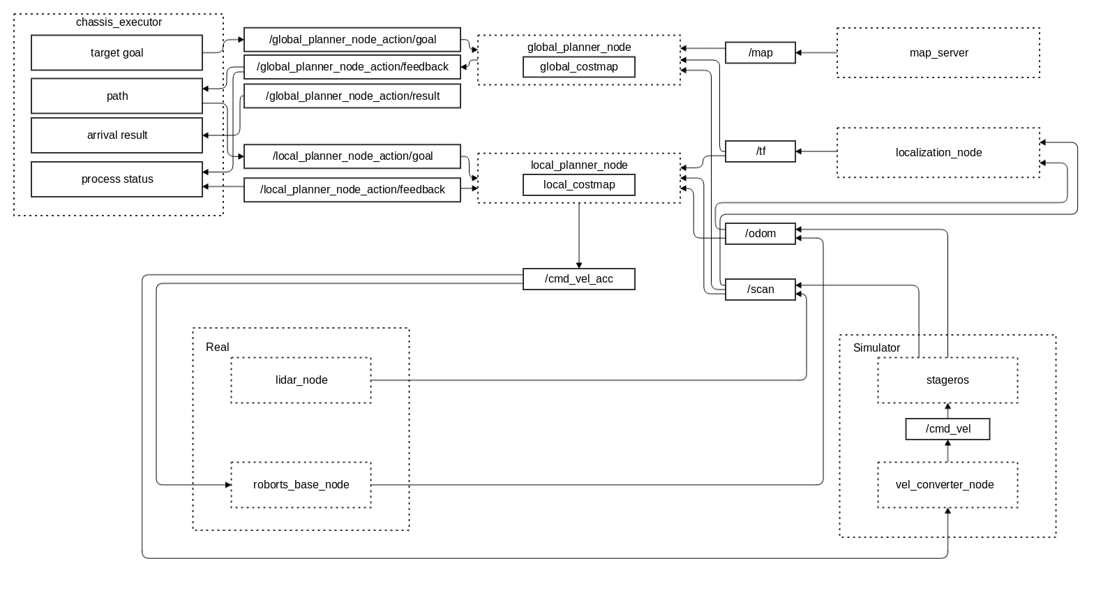
121 |
122 | #### Gimbal scheduling Modules
123 |
124 | The gimbal scheduling modules includes a task scheduling interface with different levels of abstraction for the gimbal. The operation block diagram is as follows:
125 |
126 | 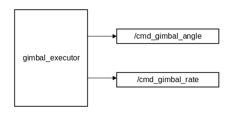
127 |
128 | It includes two task modes:
129 |
130 | - Angle control
131 |
132 | Input target angle ([roborts_msgs/GimbalAngle]())to control the angle of gimbal of the robot directly
133 |
134 | - Rate control
135 |
136 | [**deprecated**] Input target rate ([roborts_msgs/GimbalRate]())to control the rate of gimbal of the robot directly
137 |
138 |
139 |
140 |
141 | ## Compile and Run
142 |
143 | ### Compile
144 |
145 | Compile in the workspace of ROS
146 |
147 | ```shell
148 | catkin_make -j4 behavior_test_node
149 | ```
150 |
151 | ### Run
152 |
153 |
154 | Test in the simulation environment
155 |
156 | ```shell
157 | roslaunch roborts_bringup roborts_stage.launch
158 | ```
159 |
160 | Start the testing nodes of behavior
161 |
162 | ```shell
163 | rosrun roborts_decision behavior_test_node
164 | ```
165 |
166 | Input different digital command like 1/2/3/4/5/6 and you can switch to perform different behaviors
167 |
168 |
169 |
170 |
171 |
172 |
173 |
--------------------------------------------------------------------------------
/en/sdk_docs/roborts_detection.md:
--------------------------------------------------------------------------------
1 | # Detection Module
2 |
3 | ## Module Introduction
4 |
5 | Decision module provides tools to detect robot armor in ICRA Robomaster 2019 AI Challenge, and it also includes a simple analysis of the projectile model. (for more information, see the PDF documentation [projectile model analysis](https://raw.githubusercontent.com/RoboMaster/RoboRTS-Tutorial/master/pdf/projectile_model.pdf))
6 |
7 | This module is a submodule of `roborts_detection` and depends on the abstract factory pattern and parameter loading in module `roborts_common`. The module file directory is shown as below.
8 |
9 | ```bash
10 | roborts_detection
11 | ├── package.xml
12 | ├── CMakeLists.txt
13 | ├── armor_detection # Algorithms for armor detection
14 | │ ├── CMakeLists.txt
15 | │ ├── config
16 | │ │ └── armor_detection.prototxt # Config file for armor detecion parameters
17 | │ ├── armor_detection_algorithms.h # Header file for armor detection algorithms (all algorithm's header file should be included here)
18 | │ ├── armor_detection_base.h # Base class of the armor detection class
19 | │ ├── armor_detection_client.cpp # Client of actionlib for armor detection, for development usages
20 | │ ├── armor_detection_node.cpp # ROS node for internal logic of armor detection
21 | │ ├── armor_detection_node.h # Header/Entry file for the armor detection node
22 | │ ├── gimbal_control.cpp # Calculate gimbal's pitch and yaw according to projectile model
23 | │ ├── gimbal_control.h
24 | │ └── proto
25 | │ ├── armor_detection.pb.cc
26 | │ ├── armor_detection.pb.h
27 | │ └── armor_detection.proto # Structure description file for parameters used by armor detection node
28 | │ ├── constraint_set # Armor detection algorithm, identifies armor using armor characteristics
29 | │ │ ├── CMakeLists.txt
30 | │ │ ├── config
31 | │ │ │ └── constraint_set.prototxt # Adjustable armor detection parameters
32 | │ │ ├── constraint_set.cpp
33 | │ │ ├── constraint_set.h
34 | │ │ └── proto
35 | │ │ ├── constraint_set.pb.cc
36 | │ │ ├── constraint_set.pb.h
37 | │ │ └── constraint_set.proto # Structure description file for parameters used by constraint set
38 | ├── cmake_module
39 | │ ├── FindEigen3.cmake
40 | │ └── FindProtoBuf.cmake
41 | └── util
42 | ├── CMakeLists.txt
43 | └── cv_toolbox.h # Image data subscriber used by the detection node. It acts as a tool box for common image processing functions.
44 | ```
45 |
46 | The ROS node graph of armor_detection_node can be shown as follows:
47 |
48 | 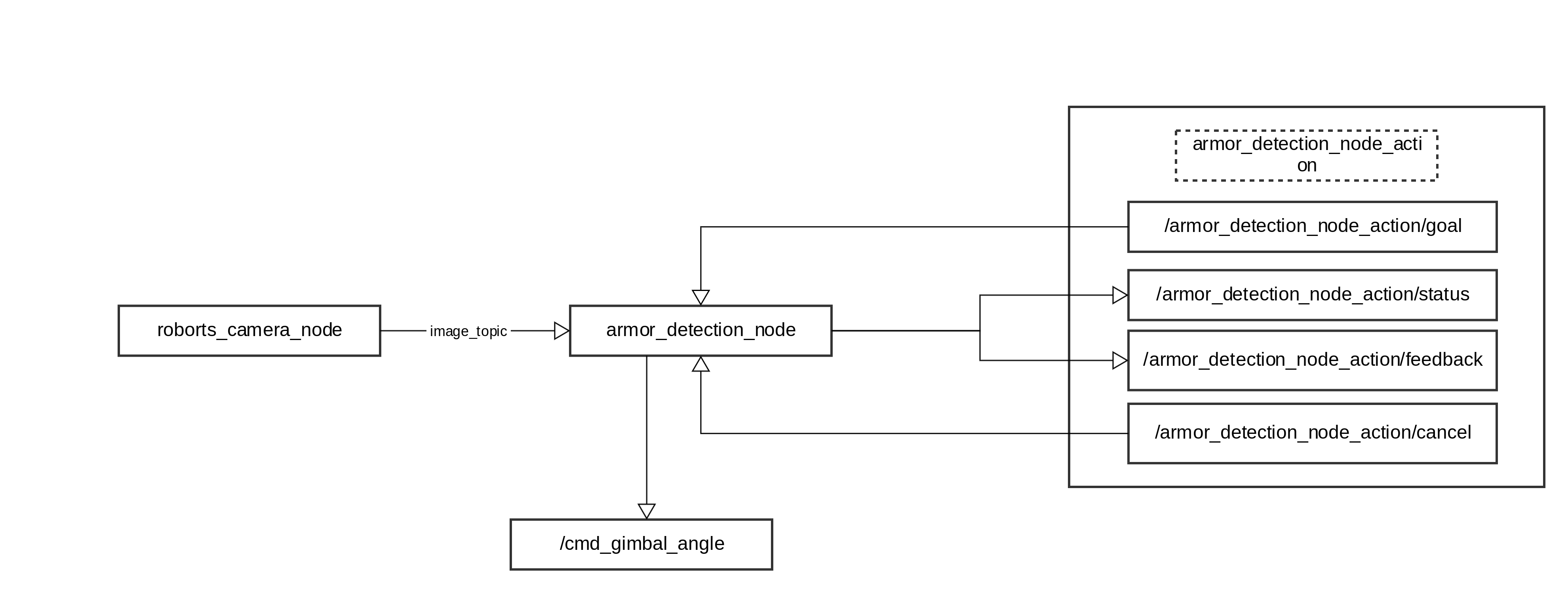
49 |
50 | Inputs and outputs of the node are as follows:
51 |
52 | ### Input
53 |
54 | - /camera_name/image_raw ([sensor_msgs/Image](http://docs.ros.org/melodic/api/sensor_msgs/html/msg/Image.html))
55 |
56 | (requried) Obtained by subscribing to `roborts_camera`, used for armor detection.
57 |
58 | - /camera_name/camera_info ([sensor_msgs/CameraInfo](http://docs.ros.org/melodic/api/sensor_msgs/html/msg/CameraInfo.html))
59 |
60 | (requried) Obtained by subscribing to `roborts_camera`, used to calculate PnP and get 3D coodinates of the target.
61 |
62 | ### Output
63 |
64 | - /armor_detection_node_action/feedback (roborts_msgs/action/ArmorDetection)
65 |
66 | `Actionlib Server` responds in real-time with location data of detected armor; the interface is wrapped by Actionlib.
67 |
68 | - /armor_detection_node_action/status ([actionlib_msgs/GoalStatusArray](http://docs.ros.org/melodic/api/actionlib_msgs/html/msg/GoalStatusArray.html))
69 |
70 | `Actionlib Server` responds in real-time with states of the detection node; the interface is wrapped by Actionlib.
71 |
72 |
73 | - /cmd_gimbal_angle (roborts_msgs/msgs/GimbalAngle)
74 |
75 | Publish gimbal control messages.
76 |
77 | ### Related Parameters
78 |
79 | For definitions of parameters see `proto/armor_detection.proto`,for parameter config data see `config/armor_detection.prototxt`.
80 |
81 | - name(`string`)
82 |
83 | Name of the armor detection algorithm
84 |
85 | - selected_algorithm(`string`)
86 |
87 | Selected detection algorithm name
88 |
89 | - undetected_armor_delay(`uint32`)
90 |
91 | Counter variable that keeps track of times when no armor is detected and data of the previous frame is published
92 |
93 | - camera_name(`string`)
94 |
95 | Camera name, should be identical to camera_name in the config file under roborts_camera
96 |
97 | - camera_gimbal_transform(`CameraGimbalTransform`) # composite data
98 |
99 | Transformation matrix for camera and gimbal, including the following parameters
100 |
101 | - offset_x(`float`)
102 |
103 | Offset of camera and gimbal in x direction
104 |
105 | - offset_y
106 |
107 | Offset of camera and gimbal in y direction
108 |
109 | - offset_z
110 |
111 | offset of camera and gimbal in z direction
112 |
113 | - offset_pitch
114 |
115 | Offset of pitch angle of camera and gimbal
116 |
117 | - offset_yaw
118 |
119 | Offset of yaw angle of camera and gimbal
120 |
121 | - projectile_model_info(`ProjectileModelInfo`) # composite data
122 |
123 | Projectile initial parameters, used for model analysis, including the following parameters
124 |
125 | - init_v(`float`)
126 |
127 | Initial velocity of the projectile
128 |
129 | - init_k(`float`)
130 |
131 | Air friction constant, for more details see projectile_model.pdf
132 |
133 | ## Compile and Run
134 |
135 | ### Compile
136 |
137 | Compile inside a ros workspace
138 |
139 | ```shell
140 | catkin_make -j4 armor_detection_client armor_detection_node
141 | ```
142 |
143 | ### Run
144 |
145 | Run the armor detection node
146 |
147 | ```shell
148 | rosrun roborts_detection armor_detection_node
149 | ```
150 |
151 | In the actual debugging process, you may need to run the armor_detection_client node
152 |
153 | ```shell
154 | rosrun roborts_detection armor_detection_client
155 | ```
156 |
157 |
158 |
159 |
160 |
161 |
--------------------------------------------------------------------------------
/en/sdk_docs/roborts_localization.md:
--------------------------------------------------------------------------------
1 | # Localization
2 |
3 | ## Module Introduction
4 |
5 | The localization node is a required dependency in the localization system. By analysing data from sensors using specific algorithms, the node acquires the transformation of coordinate systems from the robot and the map, which indicates the pose and position of the robot. The default localization algorithm in `roborts_localization` is AMCL algorithm. For more information about AMCL and relative parameters, see [AMCL](en/sdk_docs/roborts_localization?id=amcl).
6 |
7 |
8 | The data flow diagram is as follows:
9 |
10 | 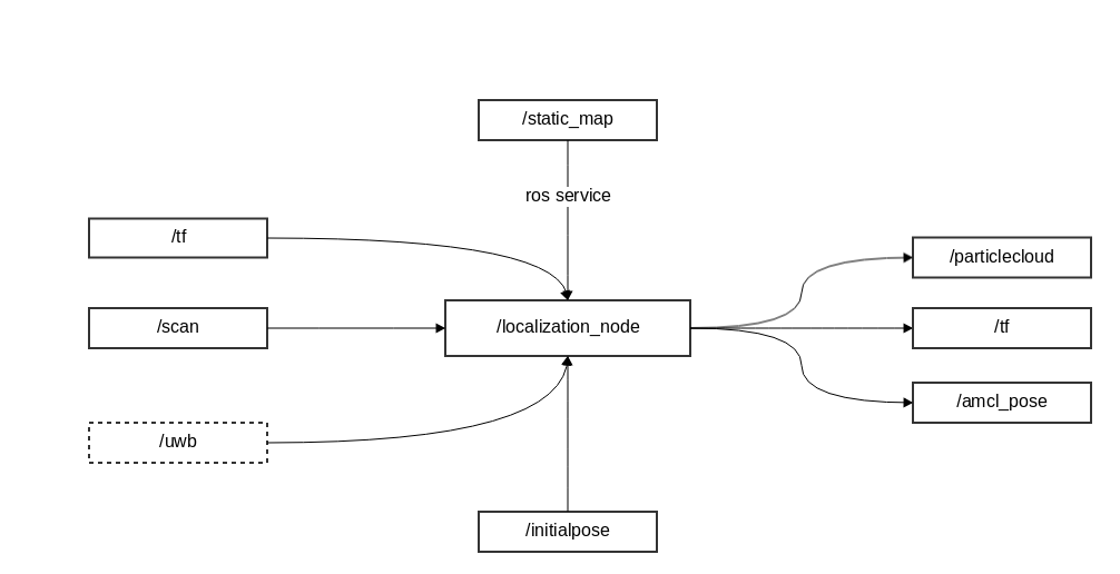
11 |
12 |
13 | The file directory is as shown below:
14 |
15 | ```bash
16 | ├── CMakeLists.txt
17 | ├── cmake_module
18 | │ ├── FindEigen3.cmake
19 | │ └── FindGlog.cmake
20 | ├── config
21 | │ └── localization.yaml # parameter config file for localization, loaded in the launch file
22 | ├── localization_config.h # parameter structure class for localization
23 | ├── localization_math.cpp
24 | ├── localization_math.h # common math related functions, for internal use only
25 | ├── localization_node.cpp # main node and main function
26 | ├── localization_node.h
27 | ├── log.h # Glog Wrapper
28 | ├── package.xml
29 | ├── types.h # Type define
30 | ├── amcl # AMCL algorithm directory
31 | │ ├── amcl_config.h # AMCL parameter config
32 | │ ├── amcl.cpp # AMCL main logic
33 | │ ├── amcl.h
34 | │ ├── CMakeLists.txt
35 | │ ├── config
36 | │ │ └── amcl.yaml # AMCL parameter config file, loaded in the launch file
37 | │ ├── map
38 | │ │ ├── amcl_map.cpp
39 | │ │ └── amcl_map.h # AMCL map related calculation
40 | │ ├── particle_filter # particle filter directory
41 | │ │ ├── particle_filter.cpp
42 | │ │ ├── particle_filter_gaussian_pdf.cpp
43 | │ │ ├── particle_filter_gaussian_pdf.h
44 | │ │ ├── particle_filter.h
45 | │ │ ├── particle_filter_kdtree.cpp
46 | │ │ ├── particle_filter_kdtree.h
47 | │ │ └── particle_filter_sample.h
48 | │ └── sensors # Odometer sensor model and lidar sensor model
49 | │ ├── sensor_laser.cpp
50 | │ ├── sensor_laser.h
51 | │ ├── sensor_odom.cpp
52 | │ └── sensor_odom.h
53 | ```
54 |
55 |
56 |
57 |
58 | Localization node can be started independently from the command line:
59 |
60 | ```bash
61 | # compile roborts_localization
62 | catkin_make -DCMAKE_BUILD_TYPE=Release localization_node
63 |
64 | rosrun roborts_localization localization_node
65 | ```
66 |
67 |
68 | Or run the node from launch file:
69 |
70 | ```xml
71 |
72 |
73 |
74 |
75 |
76 |
77 | ```
78 |
79 | Test result in RViz:
80 |
81 | 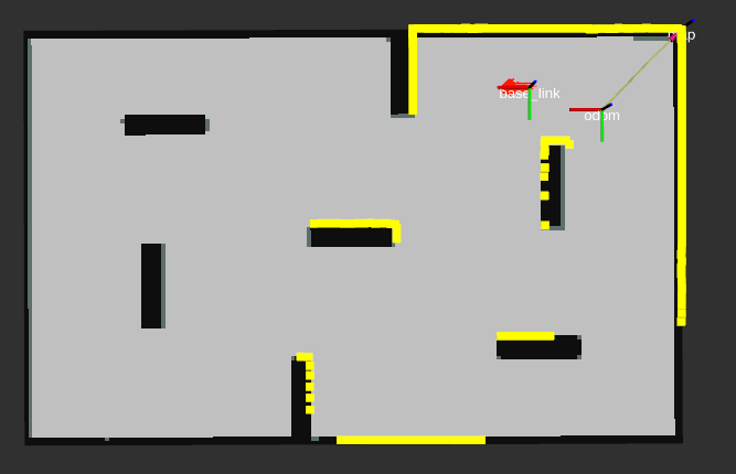
82 |
83 |
84 |
85 | ## Input
86 |
87 | * /map ([nav_msgs/OccupancyGrid](http://docs.ros.org/api/nav_msgs/html/msg/OccupancyGrid.html))
88 |
89 | (required) Subscribe to static map data.
90 |
91 | * /tf ([tf/tfMessage](http://docs.ros.org/api/tf/html/msg/tfMessage.html))
92 |
93 | (required) Obtain transformation between coordinate systems. (odom->bask_link)
94 |
95 | * /scan ([sensor_msgs/LaserScan](http://docs.ros.org/api/sensor_msgs/html/msg/LaserScan.html))
96 |
97 | (required) Subscribe to laser scan data.
98 |
99 | * /initialpose ([geometry_msgs/PoseWithCovarianceStamped](http://docs.ros.org/api/geometry_msgs/html/msg/PoseWithCovarianceStamped.html))
100 |
101 | (optional) Estimate the pose and initialize the particle filter with this mean and variance. Corresponds to 2D Pose Estimate in Rviz.
102 |
103 | * /uwb ([geometry_msgs/PoseStamped](http://docs.ros.org/melodic/api/geometry_msgs/html/msg/PoseStamped.html))
104 |
105 | (optional) UWB data used to correct global localization data.
106 |
107 | ## Output
108 |
109 | * /amcl_pose ([geometry_msgs/PoseWithCovarianceStamped](http://docs.ros.org/api/geometry_msgs/html/msg/PoseWithCovarianceStamped.html))
110 |
111 | Estimated pose by the AMCL algorithm.
112 |
113 | * /particlecloud ([geometry_msgs/PoseArray](http://docs.ros.org/api/geometry_msgs/html/msg/PoseArray.html))
114 |
115 | The pose of the particles in the particle filter.
116 |
117 | * /tf ([tf/tfMessage](http://docs.ros.org/api/tf/html/msg/tfMessage.html))
118 |
119 | Publish the transformation between `odom` and the `map` coordinate systems.
120 |
121 |
122 | > [!NOTE]
123 | > before running `roborts_localization` make sure roborts_base and drivers for laser scan is correctly installed and running.
124 |
125 |
126 |
127 | ## Related Parameters
128 |
129 | * odom_frame_id (`string`, default: "odom")
130 |
131 | coordinate system of odom
132 |
133 | * base_frame_id (`string`, default: "base_link")
134 |
135 | coordinate system of the robot body
136 |
137 | * global_frame_id (`string`, default: "map")
138 |
139 | coordinate system of the map
140 |
141 | * laser_topic_name (`string`, default: "scan")
142 |
143 | name of the topic published by laser scan
144 |
145 | * map_topic_name (`string`, default: "map")
146 |
147 | name of the topic published by the map
148 |
149 | * init_pose_topic_name (`string`, default: "initialpose")
150 |
151 | name of the topic to which the estimated pose is sent
152 |
153 | * transform_tolerance (`double`, default: 0.1)
154 |
155 | tf publish time interval
156 |
157 |
158 | * initial_pose_x (`double`, default: 1)
159 |
160 | x position of initially estimated pose
161 |
162 | * initial_pose_y (`double`, default: 1)
163 |
164 | y position of initially estimated pose
165 |
166 | * initial_pose_a (`double`, default: 0)
167 |
168 | yaw angle of initially estimated pose
169 |
170 | * initial_cov_xx (`double`, default: 0.1)
171 |
172 | the xx covariance of the initially estimated pose
173 |
174 | * initial_cov_yy (`double`, default: 0.1)
175 |
176 | the yy covariance of the initially estimated pose
177 |
178 | * initial_cov_aa (`double`, default: 0.1)
179 |
180 | the aa covariance of the initially estimated pose
181 |
182 | * enable_uwb (`bool`, default: true)
183 |
184 | whether to enable uwb correction
185 |
186 | * uwb_frame_id (`string`, default: "uwb")
187 |
188 | UWB coordinate system
189 |
190 | * uwb_topic_name (`string`, default: "uwb")
191 |
192 | name of the topic published by UWB
193 |
194 | * use_sim_uwb (`bool`, default: false)
195 |
196 | whether to use fake UWB data generated by stage simulator
197 |
198 | * uwb_correction_frequency (`int`, default: 20)
199 |
200 | frequency of UWB correction
201 |
202 |
203 | ## AMCL
204 |
205 | ### ALgorithm Introduction
206 |
207 | 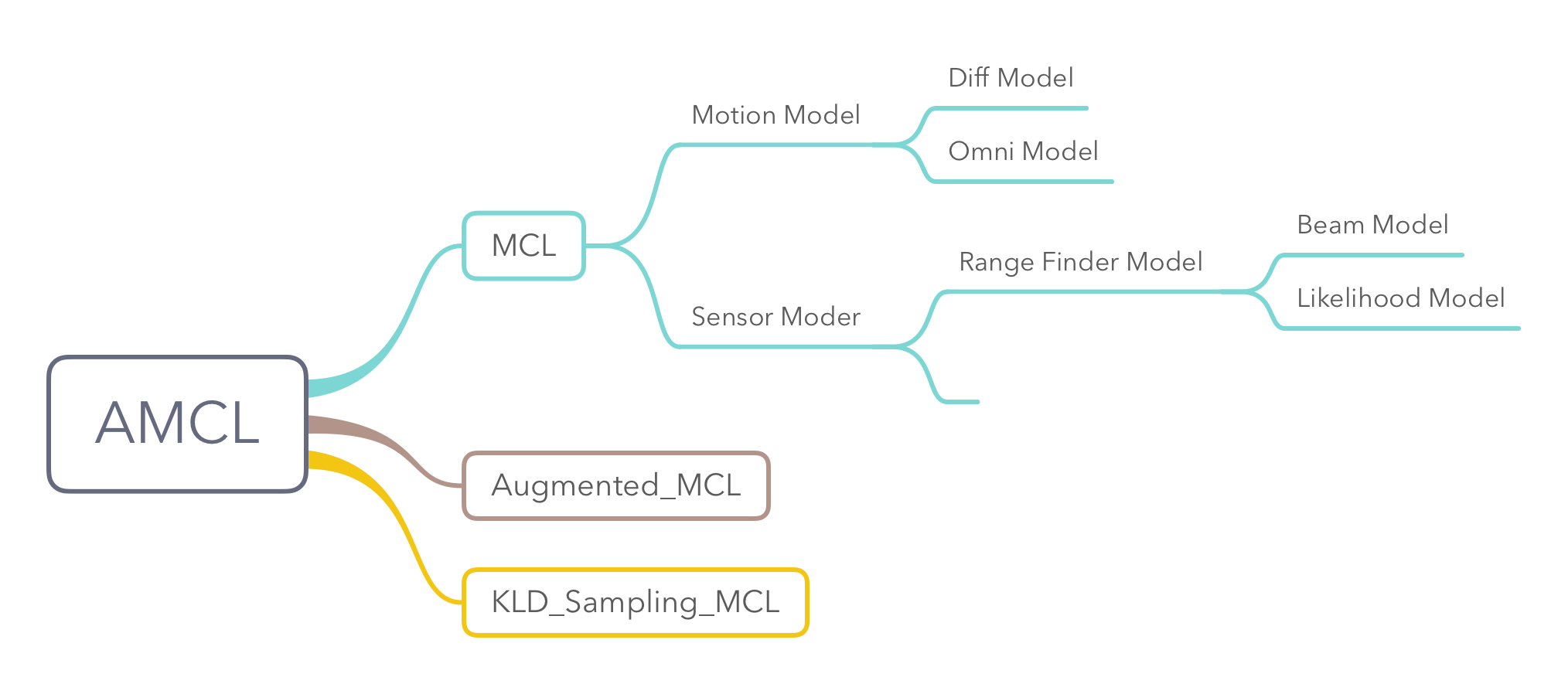
208 |
209 | Adaptive Monte Carlo Localization (AMCL) is a set of localization algorithms for 2D robot motion. The main algorithmic principle stems from the combination and implementation of the **MCL**, **Augmented_MCL**, and **KLD_Sampling_MCL** algorithms described in Probabilistic Robotics, Chapter 8.3. Meanwhile, the Motion Model described in Chapter 5 and the Sensor Model described in Chapter 6 are used for motion prediction and particle weight update in AMCL.
210 |
211 | The integrated AMCL in `roborts_localization` comes with additional functions for random angles, random positions and angle initialization, in order to facilitate rapid deployment in the competition.
212 |
213 |
214 | The basic logic of the algorithm is shown as follows.
215 | 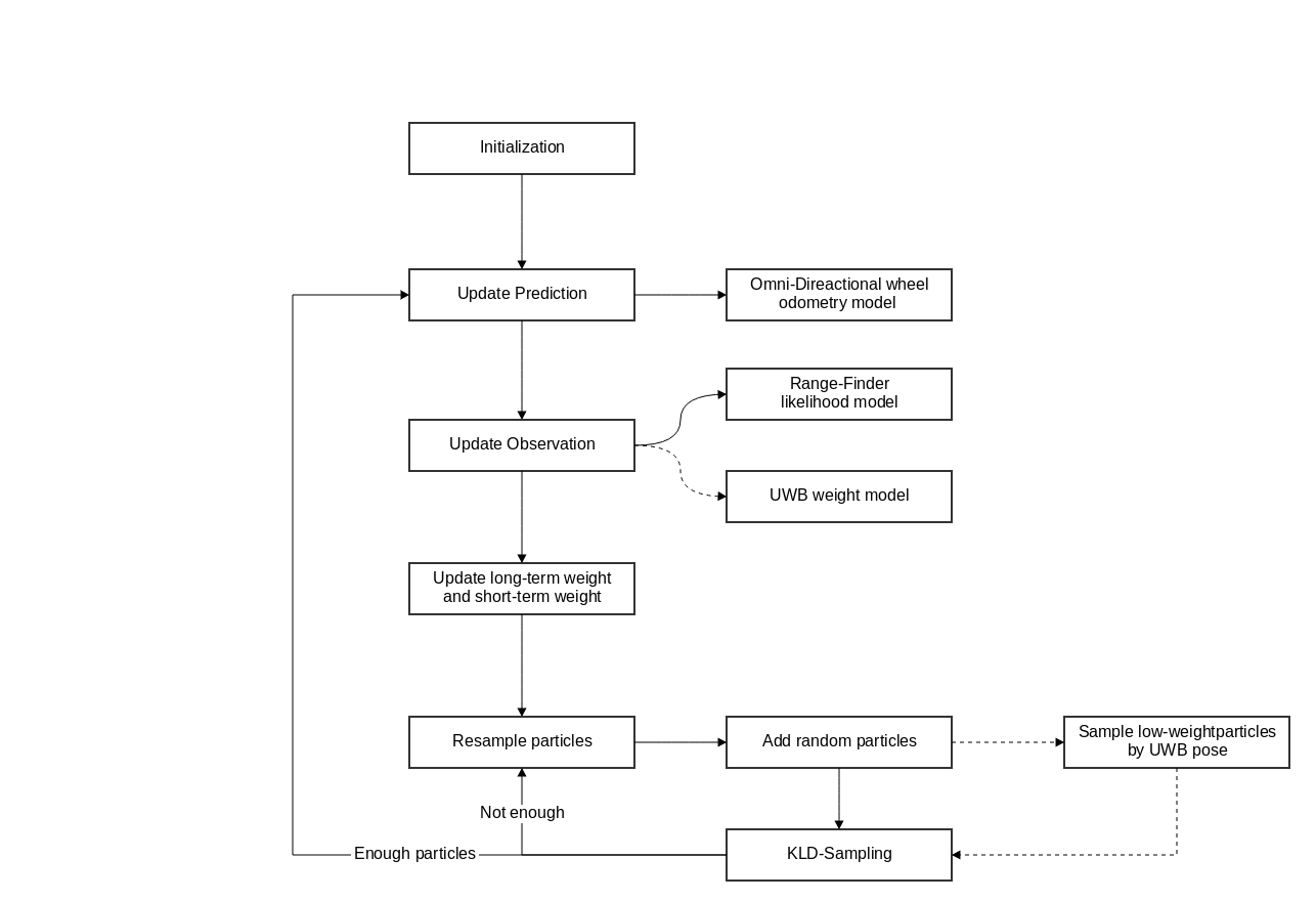
216 |
217 |
218 |
219 | ### Related Parameters
220 |
221 | * min_particles (int, default: 50)
222 |
223 | the minimum number of particles in the particle filter
224 |
225 | * max_particles (int, default: 2000)
226 |
227 | the maximum number of particles in the particle filter
228 |
229 | * use_global_localization (bool, default: false)
230 |
231 | whether to randomly initialize global localization on start up
232 |
233 | * random_heading (bool, default: false)
234 |
235 | whether to initialize random angle on start up
236 |
237 | * update_min_d (double, default: 0.1)
238 |
239 | the displacement threshold for filter update
240 |
241 |
242 | * update_min_a (double, default: 0.5)
243 |
244 | the rotation threshold for filter update
245 |
246 |
247 | * odom_model (ENUM, ODOM_MODEL_OMNI)
248 |
249 | robot motion model, currently only supports omnidirectional wheel odometer models
250 |
251 | * odom_alpha1 (double, default: 0.005)
252 |
253 | error parameter 1 for odometer model
254 |
255 | * odom_alpha2 (double, default: 0.005)
256 |
257 | error parameter 2 for odometer model
258 |
259 | * odom_alpha3 (double, default: 0.01)
260 |
261 | error parameter 3 for odometer model
262 |
263 | * odom_alpha4 (double, default: 0.005)
264 |
265 | error parameter 4 for odometer model
266 |
267 | * odom_alpha5 (double, default: 0.003)
268 |
269 | error parameter 5 for odometer model
270 |
271 | * laser_min_range (double, default: 0.15)
272 |
273 | the minimum effective distance of the laser radar
274 |
275 |
276 | * laser_max_range (double, default: 8.0)
277 |
278 | the maximum effective distance of the laser radar
279 |
280 | * laser_max_beams (int, default: 30)
281 |
282 | the maximum number of laser beams
283 |
284 | * laser_model (ENUM, default: LASER_MODEL_LIKELIHOOD_FIELD_PROB)
285 |
286 | laser radar rangefinder model. Currently only the likelihood domain improvement model is supported.
287 |
288 | * z_hit (double, default: 0.5)
289 |
290 | the $z_{hit}$ parameter in the likelihood domain model
291 |
292 | * z_rand (double, default: 0.5)
293 |
294 | the $z_{rand}$ parameter in the likelihood domain model
295 |
296 | * sigma_hit (double, default: 0.2)
297 |
298 | the $\sigma_{hit}$ parameter in the likelihood domain model
299 |
300 | * laser_likelihood_max_dist (double, default: 2.0)
301 |
302 | the maximum distance between the ranging point and the obstacle in the likelihood domain model
303 |
304 | * do_beamskip (bool, default: true)
305 |
306 | whether to ignore part of the laser beams in Position Tracking phase, in order to avoid unpredictable errors, such as moving objects.
307 |
308 | * beam_skip_distance (double, default: 0.5)
309 |
310 | the distance to ignore obstacles detected by the laser beam
311 |
312 | * beam_skip_threshold (double, default: 0.3)
313 |
314 | the threshold to ignore obstacles detected by the laser beam
315 |
316 | * beam_skip_error_threshold (double, default: 0.9)
317 |
318 | the error threshold for beam to ignore/skip obstacles
319 |
320 | * resample_interval (int, default: 2)
321 |
322 | interval for resampling
323 |
324 | * recovery_alpha_slow (double, default: 0.001)
325 |
326 | $\alpha_{slow}$ parameter in **Augmented_MCL**
327 |
328 | * recovery_alpha_fast (double, default: 0.1)
329 |
330 | $\alpha_{test}$ parameter in **Augmented_MCL**
331 |
332 | * kld_err (double, default: 0.05)
333 |
334 | $\epsilon$ parameter in **KLD_Sampling_MCL**
335 |
336 | * kld_z (double, default: 0.99)
337 |
338 | $(1-\delta)$ in **KLD_Sampling_MCL**
339 |
340 | * laser_filter_weight (double, default: 0.4)
341 |
342 | weight parameter used to filter out measured laser data that has lower weight
343 |
344 | * max_uwb_particles (int, default: 10)
345 |
346 | the maximum resampling number with UWB as the mean in resampling phase
347 |
348 | * uwb_cov_x (double, default: 0.06)
349 |
350 | the x covariance of the Gaussian distribution with UWB as the mean in resampling phase
351 |
352 | * uwb_cov_y (double, default: 0.06)
353 |
354 | the y covariance of the Gaussian distribution with UWB as the mean in resampling phase
355 |
356 | * resample_uwb_factor (double, default: 4.0)
357 |
358 | resampling factor used to determine symmetric localization
359 |
360 |
361 |
362 |
363 |
364 |
--------------------------------------------------------------------------------
/en/sdk_docs/roborts_planning_global_planner.md:
--------------------------------------------------------------------------------
1 | # Global Path Planning
2 |
3 | ## Module Introduction
4 |
5 | Global path planning (Referred to as global planning) is the first step of the motion planning of the Navigation System , after you set a target location, it will search a shortest path (a series of discrete coordinate points) without collision by perceptual global cost map , and then passed the path to the local trajectory planning module as a input to control the specific motion of the robot.
6 |
7 |
8 |
9 | The module of global path planning is located in `roborts_planner`, relevant action and mags are defined in the`roborts_msgs`and the abstract factory pattern and parameter in the`roborts_common`. The directory of module files are as follows:
10 |
11 | ```bash
12 | └── global_planner/
13 | ├── CMakeLists.txt
14 | ├── global_planner_algorithms.h #Contains header files for specific algorithms
15 | ├── global_planner_base.h #The abstract class of global planning algorithm.
16 | ├── global_planner_test.cpp #The test node of global planning.
17 | ├── global_planner_node.cpp #The planner executive node with Main functions
18 | ├── global_planner_node.h
19 | ├── a_star_planner #Astar global planning algorithm.
20 | │ └── ...
21 | ├── config
22 | │ └── global_planner_config.prototxt # Parameter configuration file
23 | └── proto
24 | ├── global_planner_config.pb.cc
25 | ├── global_planner_config.pb.h
26 | └── global_planner_config.proto # Global planning parameter definition file.
27 | ```
28 |
29 | Related algorithm of global path planning refers to [A Star Algorithm](en/sdk_docs/roborts_planning_global_planner?id=a)
30 |
31 | global_planner_node is the core planning node,ROS node graph is as follow:
32 |
33 | 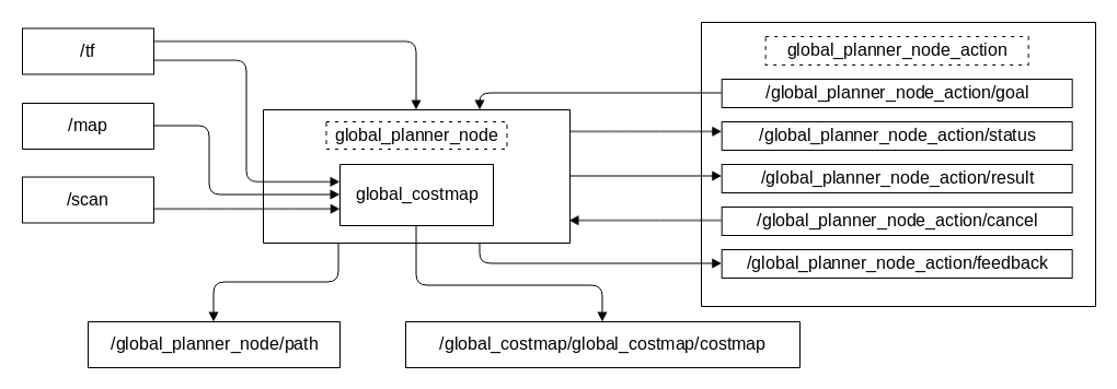
34 |
35 | The input and output of the nodes are as follows:
36 |
37 | ### Input
38 |
39 | * /tf ([tf/tfMessage](http://docs.ros.org/api/tf/html/msg/tfMessage.html))
40 |
41 | (Must)It is a base_link->map transformation that is listened to by `TransformListener`, provided by the `roborts_localization` Package within the roborts framework.
42 |
43 | * global_costmap Object (`roborts_costmap/CostmapInterface`)
44 |
45 | It can represent the global cost map (global_costmap) including the static and obstacle layers (optional), depending on the topic /tf, /map (static layer) and /scan (obstacle layer), which is provided by the `roborts_costmap` package.
46 |
47 | * /global_planner_node_action/goal ([roborts_msgs/GlobalPlannerGoal]())
48 |
49 | (Must)Enter the target of the global planning from `Actionlib Client` to `Actionlib Server`. The interface is encapsulated by Actionlib. The specific message type is([geometry_msgs/PoseStamped](http://docs.ros.org/api/geometry_msgs/html/msg/PoseStamped.html))
50 |
51 | * /global_planner_node_action/cancel ([actionlib_msgs/GoalID](http://docs.ros.org/api/actionlib_msgs/html/msg/GoalID.html))
52 |
53 | Apply`Actionlib Client`to`Actionlib Server`to cancel the running task of the global planning. The interface is encapsulated by Actionlib.
54 |
55 | ### Output
56 |
57 | * /global_planner_node_action/feedback ([roborts_msgs/GlobalPlannerFeedback]())
58 |
59 | `Actionlib Server`Real-time feedback of the planning path. The interface is encapsulated by Actionlib. Concrete message type is: [nav_msgs/Path](http://docs.ros.org/api/nav_msgs/html/msg/Path.html)
60 |
61 | * /global_planner_node_action/result ([roborts_msgs/GlobalPlannerResult]())
62 |
63 | `Actionlib Server`Feedback of the planning results, which is used to judge whether it reaches the target or failed to get the feasible plan. The interface is encapsulated by Actionlib.
64 |
65 | * /global_planner_node_action/status ([actionlib_msgs/GoalStatusArray](http://docs.ros.org/api/actionlib_msgs/html/msg/GoalStatusArray.html))
66 |
67 | `Actionlib Server`Real-time feedback of the planning status. The interface is encapsulated by Actionlib.
68 |
69 | * /global_planner_node/path ([nav_msgs/Path](http://docs.ros.org/api/nav_msgs/html/msg/Path.html))
70 |
71 | It is used to visually display paths.
72 |
73 | * /global_costmap/global_costmap/costmap ([nav_msgs/OccupancyGrid](http://docs.ros.org/api/nav_msgs/html/msg/OccupancyGrid.html))
74 |
75 | It is used to visually display the global cost map.
76 |
77 | ### Related Parameters
78 |
79 | Definition of the parameters refer to `proto/global_planner_config.proto`. Configuration of the parameters refer to `config/global_planner_config.prototxt`
80 |
81 | * selected_algorithm(`string`, default: "a_star_planner")
82 |
83 | Select the name of global planning algorithm.
84 |
85 | * frequency(`int`, default: 3)
86 |
87 | Frequency of global planning execution.
88 |
89 | * max_retries(`int`, default: 5)
90 |
91 | max allowed times of retry after the global plan failed.
92 |
93 | * goal_distance_tolerance(`double`, default: 0.15)
94 |
95 | Euclidean distance tolerance on the goal point for the global planner.
96 |
97 | * goal_angle_tolerance(`double`, default: 0.1)
98 |
99 | Angle (Unit radian) tolerance on the goal point for the global planner.
100 |
101 | ### Executing Process
102 |
103 | In the core planning nodes`global_planner_node_action`, executing process is as follows:
104 |
105 | - Initialization:
106 | - Initialize Actionlib Server,create a visible publisher
107 | - Read the parameter.
108 | - Instantiate tf listener,global_costmap objects.
109 | - Instantiate specific algorithm planner object.
110 |
111 | - After the initialization is finished, start the planning thread, ROS callback queue starts to callback in the main thread, at the meantime, Actionlib Server Callback also start to callback.
112 | - The flow diagram of the planning thread when it is executed:
113 | 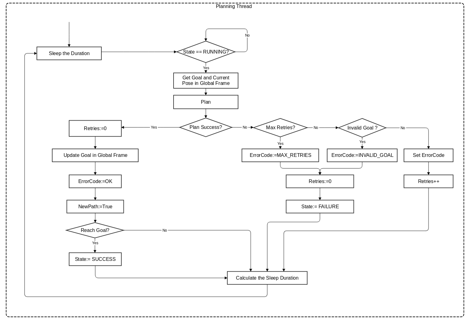
114 | - The flow diagram of Actionlib Server Callback thread:
115 | 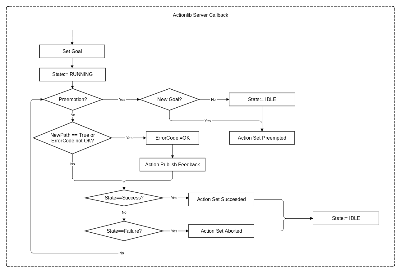
116 |
117 |
118 | ## Compile and Run
119 |
120 | ### Compile
121 |
122 | Compile in the working area of ROS:
123 |
124 | ```shell
125 | catkin_make -j4 global_planner_node global_planner_test
126 | ```
127 |
128 | ### Run
129 |
130 | Test in the simulation environment :
131 |
132 | ```shell
133 | roslaunch roborts_bringup roborts_stage.launch
134 | ```
135 |
136 | Start the testing nodes of global path planning.
137 |
138 | ```shell
139 | rosrun roborts_planning global_planner_test
140 | ```
141 | Start Rviz,it display the input and output of modules that needed,as shown in the following figure:
142 |
143 | 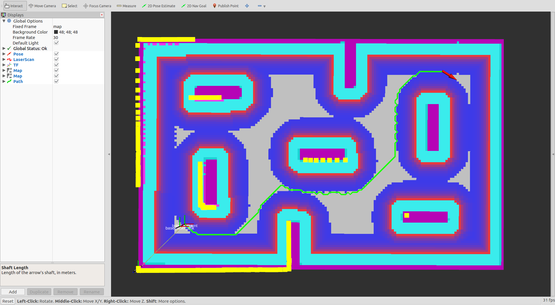
144 |
145 | - Pose: Red arrow is the planning destination.
146 | - LaserScan: Yellow point set is the data of laser radar scanning.
147 | - TF: Refer to coordinate system of TF.
148 | - Map: Gray-black part is the static map.
149 | - Map: Different colors (purple, red, blue, blue, etc.) show global cost maps at different costs.
150 | - Path: Green path is the planning path.
151 |
152 | ## A Star
153 | ### Algorithm Introduction
154 |
155 | The A*(A-Star) algorithm is the most effective method for solving the shortest path in a static road network.The formula is expressed as:
156 |
157 | $$ f(n) = g(n) + h(n) $$
158 |
159 | $f(n)$ is the value function of node n from the initial point to the target point, $g(n)$ is the actual cost from the initial node to the n node in the state space, $h(n)$ is the cost from n to the target node of the best path . In the actual global path planning, the static network routing is provided by the global cost map.
160 |
161 | ### Related Parameters
162 | * inaccessible_cost(`int`, default: 253)
163 |
164 | The cost of map grid which is impassable(deadly obstacle).
165 |
166 | * heuristic_factor(`double`, default: 1.0)
167 |
168 | Heuristic factor,refers to heuristic function: h(n) = heuristic_factor * manhattan_distance`
169 |
170 | * goal_search_tolerance(`double`, default: 0.45)
171 |
172 | Search tolerating distance of the new destination(unit:meter) , if the destination you send is impassable , then you can find a new passable destination in the given allowing distance range.
173 |
174 |
175 |
--------------------------------------------------------------------------------
/en/sdk_docs/roborts_planning_local_planner.md:
--------------------------------------------------------------------------------
1 | # Local Path Planner
2 |
3 | ## Module Introduction
4 |
5 | Local Path Planner Module calculates the optimal speed without collision for the robot, based on the Odometry information, LiDAR sensoring information, and the optimal path output from the Global Path Planner.
6 |
7 | Local Path Planner Module is located in `roborts_planner` package, it depends on the action and msgs in `roborts_msgs` package, and the abstract factory mode and parameter reader in `roborts_common`.
8 |
9 |
10 | The Local Path Planner has the following hierachy:
11 |
12 | ```bash
13 | local_planner
14 | ├── CMakeLists.txt
15 | ├── config
16 | │ └── local_planner.prototxt # Local Path Planner configuration file
17 | ├── include
18 | │ └── local_planner
19 | │ ├── proto
20 | │ │ ├── local_planner.pb.cc
21 | │ │ ├── local_planner.pb.h
22 | │ │ └── local_planner.proto # Local Path Planner parameter generation file
23 | │ ├── data_base.h # Local Path Planner data structures, used to build g2o edges and vertices
24 | │ ├── data_converter.h # Data converter, used to convert data into data_base structure
25 | │ ├── distance_calculation.h # Calculates distances between 2D points, lines, and geometry shapes
26 | │ ├── line_iterator.h # Calculates coordinates for continues line segments in discrete grid
27 | │ ├── local_planner_algorithms.h # Local Path Planner header files (all algorithm header files should be included in this file)
28 | │ ├── local_planner_base.h # Superclass for Local Path Planner algorithm
29 | │ ├── local_planner_node.h # Local Path Planner entry node
30 | │ ├── local_visualization.h # Visualization of Local Path Planner result
31 | │ ├── obstacle.h # 2D obstacle information
32 | │ ├── odom_info.h # Odometry information
33 | │ ├── optimal_base.h # Superclass for optimization algorithms
34 | │ ├── robot_footprint_model.h # Robot dimension descriptions
35 | │ ├── robot_position_cost.h # Cost calculation for robot position, used for determine the avalibility of the path
36 | │ └── utility_tool.h # Utility tool functions
37 | ├── src
38 | │ ├── local_planner_node.cpp # ros node file,used for logical scheduling inside the Local Path Planner
39 | │ ├── vel_converter.cpp # ros node file, convert the velocity into "cmd_vel" and publish it during the simulation
40 | │ ├── teb_test.cpp # timed elastic band test file
41 | │ └── ...
42 | └── timed_elastic_band
43 | ├── CMakeLists.txt
44 | ├── config
45 | │ └── timed_elastic_band.prototxt # timed elastic band configuration file
46 | ├── include
47 | │ └── timed_elastic_band
48 | │ ├── proto
49 | │ │ ├── timed_elastic_band.pb.cc
50 | │ │ ├── timed_elastic_band.pb.h
51 | │ │ └── timed_elastic_band.proto
52 | │ ├── teb_local_planner.h # timed elastic band implementation,inherited from local_planner_base.h
53 | │ ├── teb_optimal.h # g2o optimization logic,inherited from optimal_base.h
54 | │ └── ... # other g2o edge and vertex files
55 | └── src
56 | ├── teb_local_planner.cpp # timed elastic band implementation
57 | ├── teb_optimal.cpp # g2o optimization logic
58 | └── ...
59 |
60 | ```
61 |
62 | Local Path Planner related algorithms please refer to [Time Elastic Band](en/sdk_docs/roborts_planning_local_planner?id=timed-elastic-band)
63 |
64 |
65 | local_planner_node is the core planning node,the ROS node graph is shown below:
66 |
67 | 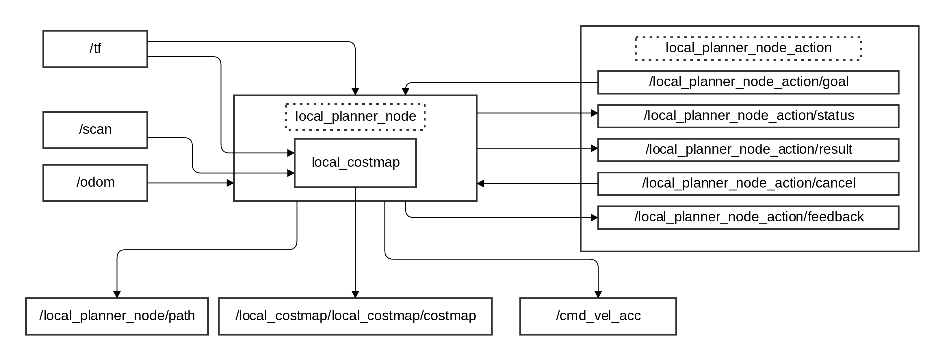
68 |
69 | The output of the node as follows:
70 |
71 | ### Input
72 |
73 | - /tf ([tf/tfMessage](http://docs.ros.org/api/tf/html/msg/tfMessage.html))
74 |
75 | (Required) Use `TransformListener` to monitor the conversion of map->odom,provided by roborts_localization package in roborts framework
76 |
77 | - local_costmap object(`roborts_costmap/CostmapInterface`)
78 |
79 | (Required) Can be used to represents the local grid cost map in obstacle layer(local_costmap), depends on topic /tf, /scan(obstacle layer),provided by roborts_costmap package in roborts framework.
80 |
81 | - /local_planner_node_action/goal (roborts_msgs/LocalPlannerGoal)
82 |
83 | (Required) From `Actionlib Client` to `Actionlib Server` input the path generated by Global Path Planner, the interface is encapsulted using Actionlib,the topic type is ([nav_msgs/Path](http://docs.ros.org/melodic/api/nav_msgs/html/msg/Path.html))
84 |
85 | - /locall_planner_node_action/cancel ([actionlib_msgs/GoalID](http://docs.ros.org/melodic/api/actionlib_msgs/html/msg/GoalID.html))
86 |
87 | From `Actionlib Client` to `Actionlib Server` to apply calceling the Local Planning task, the interface is encapsulted using Actionlib.
88 |
89 | ### Output
90 |
91 | - /local_planner_node_action/feedback (roborts_msgs/LocalPlannerFeedback)
92 |
93 | `Actionlib Server` generates real-time feedback of the error code and error message for Local Path Planner, the interface is encapsulted using Actionlib.
94 |
95 | - /local_planner_node_action/result (roborts_msgs/LocalPlannerResult)
96 |
97 | Not used
98 |
99 | - /local_planner_node_action/status ([actionlib_msgs/GoalStatusArray](http://docs.ros.org/melodic/api/actionlib_msgs/html/msg/GoalStatusArray.html))
100 |
101 | `Actionlib Server` generates the real-time feedback of the planning status, the interface is encapsulted using Actionlib.
102 |
103 | - /local_planner_node/trajectory([nav_msgs/Path](http://docs.ros.org/melodic/api/nav_msgs/html/msg/Path.html))
104 |
105 | Used for visualizing the path of Local Planner.
106 |
107 | - /local_costmap/local_costmap/costmap ([nav_msgs/OccupancyGrid](http://docs.ros.org/melodic/api/nav_msgs/html/msg/OccupancyGrid.html))
108 |
109 | Used for visualizing the Local Grid Costmap.
110 |
111 |
112 |
113 | ## Compile and Run
114 |
115 | ### Compile
116 |
117 | Before compiling, make sure installed all the dependencies. In your ROS workspace run the following command
118 |
119 | ```shell
120 | catkin_make local_planner_node vel_converter teb_test
121 | ```
122 |
123 | ### Run
124 |
125 | ```shell
126 | # Launch the Local Planner node
127 | rosrun roborts_planning local_planner_node
128 | # Launch vel_converter
129 | rosrun roborts_planning vel_converter
130 | # Launch timed elastic band test node
131 | rosrun roborts_planning teb_test
132 | ```
133 |
134 | Or using launch file
135 |
136 | ```xml
137 |
138 |
139 |
140 |
141 | ```
142 |
143 | ## Timed Elastic Band
144 | ### Algorithm Introduction
145 |
146 | The algorithm built-in the objective function for the path execution time, optimizes the actual moving path and calculates the optimal velocity, while keeping the safe distance with obstacles, and comply with the robot Kinematics. More theoretical detail can be found in paper:
147 |
148 | * C. Rösmann, F. Hoffmann and T. Bertram: Integrated online trajectory planning and optimization in distinctive topologies, Robotics and Autonomous Systems, Vol. 88, 2017, pp. 142–153.
149 |
150 | ### Related Parameters
151 |
152 | #### Path Parameters
153 |
154 | * teb_autosize
155 |
156 | Whether or not re-calculating the path
157 |
158 | * dt_ref
159 |
160 | Initial time constant
161 |
162 | * dt_hysteresis
163 |
164 | Time compensate constant
165 |
166 | * global_plan_overwrite_orientation
167 |
168 | Whether or not re-write the orientation for Path Planning position
169 |
170 | * allow_init_with_backwards_motion
171 |
172 | Whether or not allowing backward motion
173 |
174 | * global_plan_viapoint_sep
175 |
176 | Choose required Global Path Planning point
177 |
178 | * via_points_ordered
179 |
180 | Go to the waypoints via points order
181 |
182 | * max_global_plan_lookahead_dist
183 |
184 | Look ahead distance for Local Path Planning
185 |
186 | * exact_arc_length
187 |
188 | Arc length between two positions
189 |
190 | * force_reinit_new_goal_dist
191 |
192 | Force reinitialize new goal for Local Path Planner
193 |
194 | * feasibility_check_no_poses
195 |
196 | Calculate number of feasibility points for path
197 |
198 | * publish_feedback
199 |
200 | Not used
201 |
202 | * min_samples
203 |
204 | Minimum samples for path
205 |
206 | * max_samples
207 |
208 | Maximum samples for path
209 |
210 |
211 | #### Kinematics Parameters
212 |
213 |
214 | * max_vel_x
215 |
216 | Maximum forward velocity
217 |
218 | * max_vel_x_backwards
219 |
220 | Maximum backward velocity
221 |
222 | * max_vel_y
223 |
224 | Maximum translation velocity
225 |
226 | * max_vel_theta
227 |
228 | Maximum angular velocity
229 |
230 | * acc_lim_x
231 |
232 | Maximum forward/backward acceleration
233 |
234 | * acc_lim_y
235 |
236 | Maximum translation acceleration
237 |
238 | * acc_lim_theta
239 |
240 | Maximum angular acceleration
241 |
242 | * min_turning_radius
243 |
244 | Minimum turning radius
245 |
246 | * wheelbase
247 |
248 | Not used
249 |
250 | * cmd_angle_instead_rotvel
251 |
252 | Not used
253 |
254 | #### Tolerance Parameters
255 |
256 | * xy_goal_tolerance
257 |
258 | Goal distance tolerance
259 |
260 | * yaw_goal_tolerance
261 |
262 | Goal angular tolerance
263 |
264 | * free_goal_vel
265 |
266 | Free goal velocity
267 |
268 |
269 | #### Obstacle Parameters
270 |
271 | * min_obstacle_dist
272 |
273 | Minimum obstacle distance
274 |
275 | * inflation_dist
276 |
277 | Obstacle inflation distance
278 |
279 | * include_costmap_obstacles
280 |
281 | Not used, whether include costmap obstacles
282 |
283 | * costmap_obstacles_behind_robot_dist
284 |
285 | Threshold for obstacle costmap behind the robot
286 |
287 | * obstacle_poses_affected
288 |
289 | Obstacles that affect the number of waypoints, only works when legacy_obstacle_association is true
290 |
291 | * legacy_obstacle_association
292 |
293 | Select optimization objective to be the closest waypoint to the obstacle, or the closest obstacle to the waypoint
294 |
295 | * obstacle_association_cutoff_factor
296 |
297 | Do not consider the factor of obstacle, only works when legacy_obstacle_association is false
298 |
299 | * obstacle_association_force_inclusion_factor
300 |
301 | Force consider the factor of obstacle, only works when legacy_obstacle_association is false
302 |
303 | #### Optimization Parameters
304 |
305 | * no_inner_iterations
306 |
307 | The number of iterations for the solver when the path adjustment is done
308 |
309 | * no_outer_iterations
310 |
311 | The number of automatic path adjustment
312 |
313 | * optimization_activate
314 |
315 | Whether or not start optimization
316 |
317 | * optimization_verbose
318 |
319 | Whether or not output debug message for optimization
320 |
321 | * penalty_epsilon
322 |
323 | Constrained cost function conpensition
324 |
325 | * weight_max_vel_x
326 |
327 | Maximum x velocity weight
328 |
329 | * weight_max_vel_y
330 |
331 | Maximum y velocity weight
332 |
333 | * weight_max_vel_theta
334 |
335 | Maximum angular velocity weight
336 |
337 | * weight_acc_lim_x
338 |
339 | Maximum x acceleration weight
340 |
341 | * weight_acc_lim_y
342 |
343 | Maximum y acceleration weight
344 |
345 | * weight_acc_lim_theta
346 |
347 | Maximum angular acceleration weight
348 |
349 | * weight_kinematics_nh
350 |
351 | Non complete Kinematics constraint weight
352 |
353 | * weight_kinematics_forward_drive
354 |
355 | Forward drive weight
356 |
357 | * weight_kinematics_turning_radius
358 |
359 | Minimum steering radius weight, car like model
360 |
361 | * weight_optimaltime
362 |
363 | Optimization track time weight
364 |
365 | * weight_obstacle
366 |
367 | Minimum distance to obstacle weight
368 |
369 | * weight_inflation
370 |
371 | Weight after inflation
372 |
373 | * weight_dynamic_obstacle
374 |
375 | Dynamic obstacle weight
376 |
377 | * weight_viapoint
378 |
379 | Minimum distance to waypoint weight
380 |
381 | * weight_adapt_factor
382 |
383 | Weight adaptation factor, only used in obstacle for now
384 |
385 | * weight_prefer_rotdir
386 |
387 | Steering weight
--------------------------------------------------------------------------------
/en/software_framework.md:
--------------------------------------------------------------------------------
1 | # Software Architecture
2 | The entire software system decouples the driver module, function module and algorithm module to enhance the portability of the platform and improve the efficiency of collaborative development by developers in different fields.
3 |
4 | The entire software architecture is shown below:
5 |
6 | 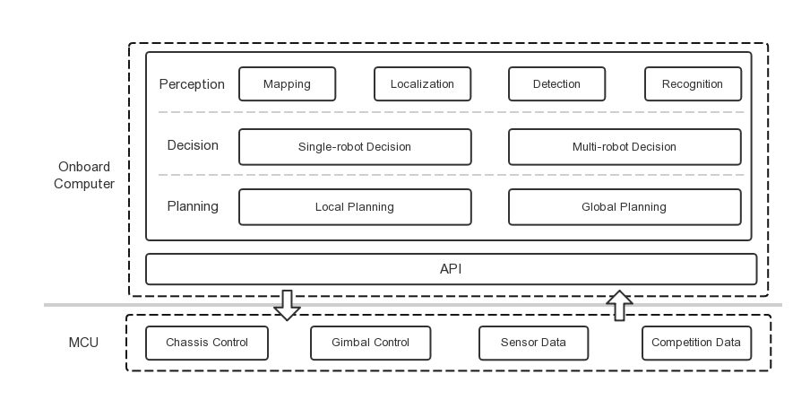
7 |
8 | Based on the platform, developers can develop in a buttom-up fashion to control the robot to complete different tasks. The whole framework is divided into two parts:
9 |
10 |
11 | As the low-level computing platform, the STM32 microcontroller runs RTOS (Real-Time Operating System) with limited computing power to perform various real-time tasks:
12 |
13 | - Closed-loop control tasks with feedback based on encoder or IMU
14 |
15 | - Acquisition, pre-processing and forwarding of sensor information for pose estimation
16 |
17 | - Forward information related to the competition, such as robot HP value, etc.
18 |
19 | On-board computing devices (such as Manifold 2) act as the upper-level computing platform, responsible for the execution of various algorithms with large amounts of computation:
20 |
21 | - Environment perception, including real-time localization, mapping, target detection, identification and tracking
22 |
23 | - Motion planning, including global planning (path planning), local planning (trajectory planning)
24 |
25 | - An observation-action-based decision model interface that adapts to various decision frameworks such as FSM (Finite State Machine), Behavior Tree and other learning-based decision frameworks.
26 |
27 | The two computing platforms communicate with the specified open source protocol through the serial port. The platform also provides a ROS-based API interface, which can be used for secondary development in ROS using C++ or Python. Based on this interface, developers can control the movement of the chassis and the gimbal, control the launching mechanism to fire the projectile by changing the input frequency, the velocity of projectiles and the quantity of projectiles, and receive the sensor information and game data in real-time. In more advanced applications, developers can define their own protocols based on the related documentation in [roborts_base](en/sdk_docs/roborts_base) to extend the capabilities of the robot.
28 |
29 | # Applications
30 |
31 | The original intention of RoboRTS and RoboMaster mobile robot platform is to encourage more developers to participate in the research of robot intelligent decision-making under different scenarios and rules. The first step is to implement some robot perception or planning algorithms based on this hardware platform, so the observation space and action space can be abstracted, and better decision models can be constructed.
32 |
33 | Our primary scenario is the decision-making of robotic competition, as shown below:
34 |
35 | Pursuit and search:
36 |
37 | 
38 |
39 | Patrol:
40 |
41 | 
42 |
43 |
44 |
45 |
46 |
--------------------------------------------------------------------------------
/hardware_specifications.md:
--------------------------------------------------------------------------------
1 | ## 结构组成
2 | RoboMaster机器人平台基于模块化设计,支持快拆结构,各模块可单独编程与调试使用。
3 |
4 |
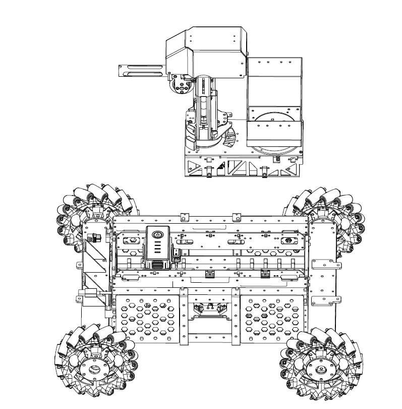
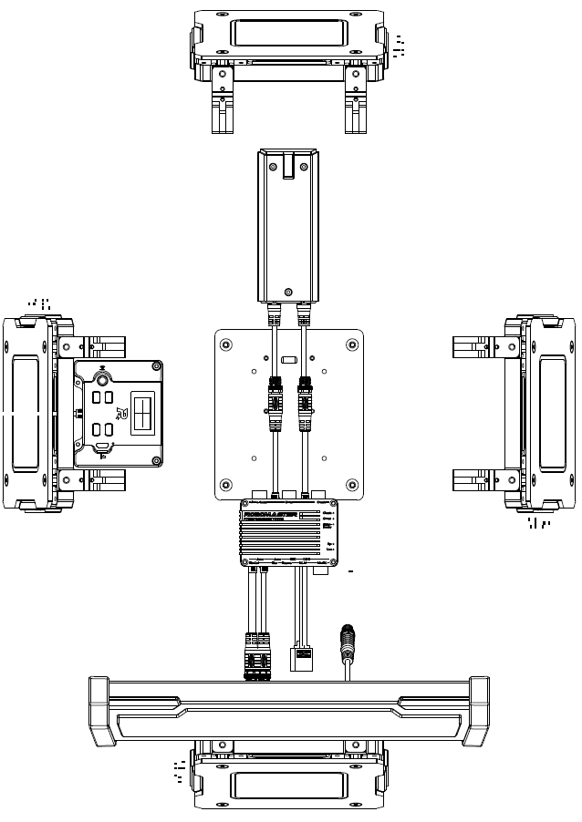 6 |
6 | 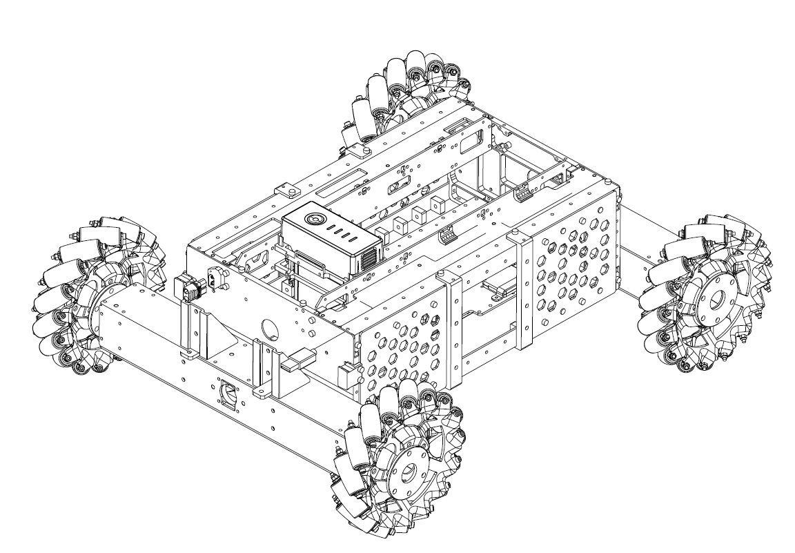 14 |
14 | 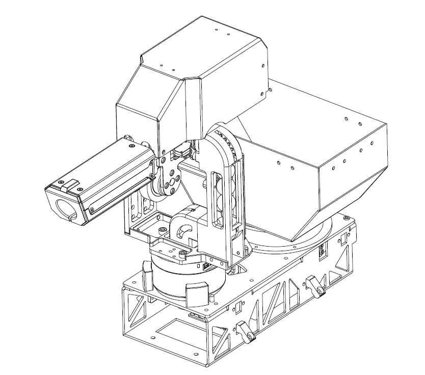 27 |
27 | 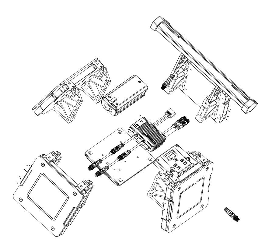 42 |
42 |