├── 10. Resources
└── README.md
├── 05. Home Network Basics
├── README.md
├── 5. Set Up a Home Router
│ ├── 2. Design Considerations
│ │ └── README.md
│ └── 1. First Time Setup
│ │ └── README.md
├── 1. Basics
│ ├── 2. Benefits of Wireless LAN
│ │ └── README.md
│ ├── 3. Components of a Home Network
│ │ └── README.md
│ ├── 4. Typical Home Network Routers
│ │ └── README.md
│ └── 1. Connecting Home Devices
│ │ └── README.md
├── 3. Wireless Standards
│ ├── 2. Wireless Settings
│ │ └── README.md
│ ├── 1. Wi-Fi Networks
│ │ └── README.md
│ └── 3. Network Mode
│ │ └── README.md
├── 4. Wireless Traffic Controls
│ └── 1. Wireless Channels
│ │ └── README.md
└── 2. Network Technologies in the Home
│ ├── 2. LAN Wireless Frequencies
│ └── README.md
│ ├── 1. The EM Spectrum
│ └── README.md
│ └── 3. Wired Network Technologies
│ └── README.md
├── _config.yml
├── 03. Network Protocols and Architecture
├── README.md
├── 1. Communication Principles
│ ├── README.md
│ ├── 4. Ethernet
│ │ ├── README.md
│ │ ├── 3. Ethernet MAC Address
│ │ │ └── README.md
│ │ ├── 2. Ethernet Evolution
│ │ │ └── README.md
│ │ └── 1. The Rise of Ethernet
│ │ │ └── README.md
│ ├── 2. Communication Standards
│ │ ├── 1. Internet and the Standards
│ │ │ └── README.md
│ │ └── 2. Network Standard Organizations
│ │ │ └── README.md
│ ├── 1. The Rules
│ │ ├── 1. The 3 Elements
│ │ │ └── README.md
│ │ └── 2. Communication Protocols
│ │ │ └── README.md
│ └── 3. Network Communication Models
│ │ └── 2. The TCP-IP Model
│ │ └── README.md
├── 2. Network Design & the Access Layer
│ ├── README.md
│ ├── 4. Broadcast Containment
│ │ ├── 3. Access Layer Communication
│ │ │ └── README.md
│ │ ├── 4. Address Resolution Protocol
│ │ │ └── README.md
│ │ ├── 1. The Ethernet Broadcast
│ │ │ └── README.md
│ │ └── 2. Broadcast Domain
│ │ │ └── README.md
│ ├── 3. The Access Layer & Devices
│ │ ├── 1. Access Layer
│ │ │ └── README.md
│ │ ├── 4. MAC Address Tables
│ │ │ └── README.md
│ │ ├── 2. Ethernet Switches
│ │ │ └── README.md
│ │ └── 3. Ethernet Hubs
│ │ │ └── README.md
│ ├── 2. Hierarchical Network Design
│ │ ├── 1. Physical & Logical Addresses
│ │ │ └── README.md
│ │ ├── 2. Benefits of Hierarchical Design
│ │ │ └── README.md
│ │ └── 3. Access, Distribution and Core Layer
│ │ │ └── README.md
│ └── 1. Encapsulation and the Ethernet Frame
│ │ ├── 1. Encapsulation
│ │ └── README.md
│ │ └── 2. Ethernet Frame
│ │ └── README.md
├── 4. The Internet Protocol
│ ├── 2. Binary Conversion of an IPv4
│ │ └── README.md
│ ├── 3. IPv4 Address Structure
│ │ ├── 2. Logical AND
│ │ │ └── README.md
│ │ ├── 3. Calculate the Number of Hosts
│ │ │ └── README.md
│ │ └── 1. Networks and Hosts
│ │ │ └── README.md
│ ├── 6. Unicast, Broadcast and Multicast Addresses
│ │ ├── 1. Unicast Transmission
│ │ │ └── README.md
│ │ ├── 2. Broadcast Transmission
│ │ │ └── README.md
│ │ └── 3. Multicast Transmission
│ │ │ └── README.md
│ ├── 1. Purpose of the IPv4
│ │ └── README.md
│ └── 5. Public and Private IP Addresses
│ │ └── 2. IPv4 Address Assignment
│ │ └── README.md
└── 3. Routing Between Networks
│ ├── 2. The Routing Table
│ ├── 2. Packet Forwarding
│ │ └── README.md
│ ├── 3. Routing Table Entries
│ │ └── README.md
│ ├── 1. Path Selection
│ │ └── README.md
│ └── 4. The Default Gateway
│ │ └── README.md
│ └── 3. Create a LAN
│ └── 1. Local Area Networks
│ └── README.md
├── 01. Internet Connection
├── 6. Online Connections
│ ├── README.md
│ ├── 1. Wireless Networks
│ │ └── README.md
│ ├── 3. Cisco Packet Tracer
│ │ ├── 2. Device Configuration in Packet Tracer
│ │ │ └── README.md
│ │ └── 1. Introduction
│ │ │ └── README.md
│ ├── 4. Network Documentation
│ │ ├── 1. Device Names & Address Planning
│ │ │ └── README.md
│ │ └── 2. Logical Network Information
│ │ │ └── README.md
│ └── 2. Local Network Connections
│ │ ├── 3. Manual & Automatic Address Assignment
│ │ └── README.md
│ │ └── 2. End Device Addressing
│ │ └── README.md
├── 5. Network Components
│ ├── 1. Network Infrastructure Symbols
│ │ └── README.md
│ ├── 2. Network Infrastructure
│ │ └── README.md
│ └── 3. End Devices
│ │ └── README.md
├── 3. Bandwidth & Throughput
│ ├── 1. Bandwidth
│ │ └── README.md
│ └── 2. Throughput
│ │ └── README.md
├── 2. Data Transmission
│ ├── 1. Types of Personal Data
│ │ └── README.md
│ └── 2. Methods of Data Transmission
│ │ └── README.md
├── 4. Clients & Servers
│ ├── 3. Peer-to-Peer Applications
│ │ └── README.md
│ ├── 4. Multiple Roles in a Network
│ │ └── README.md
│ ├── 2. Peer-to-Peer Networks
│ │ └── README.md
│ └── 1. Client & Server Roles
│ │ └── README.md
└── 1. Communications in a Connected World
│ ├── 3. Home Devices
│ └── README.md
│ ├── 4. Other Devices
│ └── README.md
│ └── 2. Mobile Devices
│ └── README.md
├── 04. Data Communications and Network Services
├── README.md
├── 3. Transport Layer Services
│ ├── README.md
│ ├── 3. Port Numbers
│ │ ├── 4. The netstat Command
│ │ │ └── README.md
│ │ ├── 2. Destination and Source Port Numbers
│ │ │ └── README.md
│ │ └── 3. Socket Pairs
│ │ │ └── README.md
│ ├── 2. TCP and UDP
│ │ ├── 2. TCP & UDP
│ │ │ └── README.md
│ │ ├── 3. TCP Reliability
│ │ │ └── README.md
│ │ ├── 1. Protocol Operations
│ │ │ └── README.md
│ │ └── 4. UDP - Best Effort Delivery
│ │ │ └── README.md
│ └── 1. Client - Server Relationship
│ │ ├── 3. URI, URN, URL
│ │ └── README.md
│ │ ├── 2. Client Requests a Webpage
│ │ └── README.md
│ │ └── 1. Client and Server Interaction
│ │ └── README.md
├── 4. Application Layer Services
│ ├── README.md
│ ├── 3. Web Clients and Servers
│ │ ├── README.md
│ │ └── 1. HTTP and HTML
│ │ │ └── README.md
│ ├── 1. Network Application Services
│ │ ├── README.md
│ │ └── 1. Common Network Application Services
│ │ │ └── README.md
│ ├── 4. FTP Clients and Server
│ │ ├── 2. FTP Client Software
│ │ │ └── README.md
│ │ └── 1. File Transfer Protocol
│ │ │ └── README.md
│ ├── 2. Domain Name System
│ │ ├── 2. DNS Servers
│ │ │ └── README.md
│ │ └── 1. Domain Name Translation
│ │ │ └── README.md
│ ├── 6. Email and Messaging
│ │ ├── 1. Email Clients and Server
│ │ │ └── README.md
│ │ ├── 3. Text Messaging
│ │ │ └── README.md
│ │ ├── 2. Email Protocols
│ │ │ └── README.md
│ │ └── 4. Internet Phonecalls
│ │ │ └── README.md
│ └── 5. Virtual Terminals
│ │ ├── 2. Security Issues with TelNet
│ │ └── README.md
│ │ └── 1. TelNet
│ │ └── README.md
├── 1. Dynamic Addressing with DHCP
│ ├── 2. DHCPv4 Configuration
│ │ ├── README.md
│ │ └── 1. DHCPv4 Operation
│ │ │ └── README.md
│ └── 1. Static and Dynamic Addressing
│ │ ├── README.md
│ │ ├── 2. Dynamic Addressing
│ │ └── README.md
│ │ ├── 1. Static Addressing
│ │ └── README.md
│ │ └── 3. DHCP Servers
│ │ └── README.md
└── 2. IPv4 and IPv6 Address Management
│ ├── 1. Network Boundaries
│ ├── README.md
│ ├── 1. Routers as Gateways
│ │ └── README.md
│ └── 2. Routers as Boundaries between Networks
│ │ └── README.md
│ ├── 2. Network Address Translation
│ ├── README.md
│ └── 1. NAT Operation
│ │ └── README.md
│ ├── 4. IPv6 Features
│ ├── 2. Link - Local Address
│ │ └── README.md
│ ├── 1. IPv6 Autoconfiguration
│ │ └── README.md
│ └── 3. IPv6 Address Representation
│ │ └── README.md
│ └── 3. IPv4 Issues
│ ├── 2. IPv6 Address Size
│ └── README.md
│ ├── 3. IPv4 and IPv6 Co-existence
│ └── README.md
│ └── 1. Need for IPv6
│ └── README.md
├── styles.css
├── 09. Intro to Cisco Networking
├── 2. Cisco IOS Command Line
│ ├── 1. IOS Navigation
│ │ ├── 1. Cisco IOS CLI
│ │ │ └── README.md
│ │ └── 2. IOS Command Modes
│ │ │ └── README.md
│ └── 2. The Command Structure
│ │ ├── 1. Basic IOS
│ │ └── README.md
│ │ └── 2. IOS Command Syntax
│ │ └── README.md
├── 4. Troubleshooting Common Network Problems
│ ├── 2. Physical Layer Problems
│ │ └── README.md
│ └── 1. The Troubleshooting Process
│ │ ├── 4. Guidelines
│ │ └── README.md
│ │ ├── 3. Structured Methods
│ │ └── README.md
│ │ ├── 2. Gather Information
│ │ └── README.md
│ │ └── 1. Overview
│ │ └── README.md
├── 1. Cisco Switches
│ ├── 3. LAN Switch Components
│ │ └── README.md
│ └── 4. In-band & Out-of-Band Management
│ │ └── README.md
└── 3. Cisco Routers
│ ├── 1. Router Components
│ └── README.md
│ ├── 2. Router Interface Ports
│ └── README.md
│ └── 3. Router Boot Process
│ └── README.md
├── .github
└── dependabot.yml
├── 08. Security Configuration
├── 3. Configure a Firewall
│ ├── 1. Firewall Overview
│ │ └── README.md
│ ├── 4. Port Forwarding
│ │ └── README.md
│ ├── 3. The DMZ
│ │ └── README.md
│ ├── 5. Port Triggering
│ │ └── README.md
│ └── 2. Firewall Operation
│ │ └── README.md
├── 2. Implement Wireless Security
│ ├── 2. Authentication and Association
│ │ └── README.md
│ ├── 1. Open Authentication
│ │ └── README.md
│ └── 3. Authentication Protocols
│ │ └── README.md
└── 1. Wireless Security Measures
│ ├── 4. Changing Default Settings
│ └── README.md
│ ├── 5. MAC Address Filtering
│ └── README.md
│ ├── 3. SSID Broadcasts
│ └── README.md
│ └── 2. A Security Plan
│ └── README.md
├── 02. Build a Simple Network
├── 7. Simple Network Using Cisco Packet Tracer
│ ├── README.md
│ ├── 2. The traceroute Command
│ │ └── README.md
│ └── 1. The ping Command
│ │ └── README.md
├── 1. Network Media Types
│ └── README.md
├── 3. Ethernet Cabling
│ └── 1. Twisted-Pair Cables
│ │ └── README.md
├── 4. Co-axial Cabling
│ └── README.md
├── 2. Common Network Cables
│ └── README.md
├── 5. Fiber-Optic Cabling
│ └── README.md
└── 6. Twisted-Pair Wiring
│ └── README.md
├── 06. Connecting to Internet
├── 2. Network Virtualization
│ ├── 1. Cloud Computing
│ │ └── README.md
│ ├── 10. SDN Architecture
│ │ └── README.md
│ ├── 7. Network Virtualization
│ │ └── README.md
│ ├── 9. Network Virtualization and SDN
│ │ └── README.md
│ ├── 8. Control Plane and Data Plane
│ │ └── README.md
│ ├── 5. Advantages of Virtualization
│ │ └── README.md
│ ├── 2. Types of Cloud
│ │ └── README.md
│ └── 3. Cloud Services
│ │ └── README.md
└── 1. ISP Connectivity Options
│ ├── 2. ISP Connections
│ └── README.md
│ ├── 1. ISP Services
│ └── README.md
│ └── 3. Cable and DSL Connections
│ └── README.md
├── CONTRIBUTING.md
├── 07. Network and Device Security
├── 5. Antimalware Software
│ ├── 4. Antispyware Software
│ │ └── README.md
│ ├── 3. Antispam Software
│ │ └── README.md
│ ├── 5. Additional Safeguards
│ │ └── README.md
│ ├── 1. Signs of Infection
│ │ └── README.md
│ └── 2. Antivirus Software
│ │ └── README.md
├── 3. Malware
│ ├── 1. Malicious Software
│ │ └── README.md
│ ├── 4. Adware and Popups
│ │ └── README.md
│ ├── 3. Spyware
│ │ └── README.md
│ ├── 2. Types of Malware
│ │ └── README.md
│ └── 5. Botnets and Zombies
│ │ └── README.md
├── 2. Social Engineering Attacks
│ ├── 1. Overview
│ │ └── README.md
│ └── 2. Types
│ │ └── README.md
├── 4. DoS Attacks
│ ├── 1. Denial of Service
│ │ └── README.md
│ └── 2. DDoS
│ │ └── README.md
└── 1. Security Threats
│ └── 2. Internal and External Threats
│ └── README.md
└── LICENSE
/10. Resources/README.md:
--------------------------------------------------------------------------------
1 |
2 |
--------------------------------------------------------------------------------
/05. Home Network Basics/README.md:
--------------------------------------------------------------------------------
1 |
2 |
--------------------------------------------------------------------------------
/_config.yml:
--------------------------------------------------------------------------------
1 | theme: jekyll-theme-hacker
--------------------------------------------------------------------------------
/03. Network Protocols and Architecture/README.md:
--------------------------------------------------------------------------------
1 |
2 |
--------------------------------------------------------------------------------
/01. Internet Connection/6. Online Connections/README.md:
--------------------------------------------------------------------------------
1 |
2 |
--------------------------------------------------------------------------------
/04. Data Communications and Network Services/README.md:
--------------------------------------------------------------------------------
1 |
2 |
--------------------------------------------------------------------------------
/01. Internet Connection/6. Online Connections/1. Wireless Networks/README.md:
--------------------------------------------------------------------------------
1 |
2 |
--------------------------------------------------------------------------------
/03. Network Protocols and Architecture/1. Communication Principles/README.md:
--------------------------------------------------------------------------------
1 |
2 |
--------------------------------------------------------------------------------
/04. Data Communications and Network Services/3. Transport Layer Services/README.md:
--------------------------------------------------------------------------------
1 |
2 |
--------------------------------------------------------------------------------
/03. Network Protocols and Architecture/2. Network Design & the Access Layer/README.md:
--------------------------------------------------------------------------------
1 |
2 |
--------------------------------------------------------------------------------
/04. Data Communications and Network Services/4. Application Layer Services/README.md:
--------------------------------------------------------------------------------
1 |
2 |
--------------------------------------------------------------------------------
/01. Internet Connection/5. Network Components/1. Network Infrastructure Symbols/README.md:
--------------------------------------------------------------------------------
1 |
2 |
--------------------------------------------------------------------------------
/styles.css:
--------------------------------------------------------------------------------
1 | body {
2 | margin: 0;
3 | background: pink;
4 | text-align: center;
5 | }
--------------------------------------------------------------------------------
/09. Intro to Cisco Networking/2. Cisco IOS Command Line/1. IOS Navigation/1. Cisco IOS CLI/README.md:
--------------------------------------------------------------------------------
1 |
2 |
--------------------------------------------------------------------------------
/05. Home Network Basics/5. Set Up a Home Router/2. Design Considerations/README.md:
--------------------------------------------------------------------------------
1 | # Design Considerations
2 |
--------------------------------------------------------------------------------
/09. Intro to Cisco Networking/2. Cisco IOS Command Line/1. IOS Navigation/2. IOS Command Modes/README.md:
--------------------------------------------------------------------------------
1 |
2 |
--------------------------------------------------------------------------------
/09. Intro to Cisco Networking/2. Cisco IOS Command Line/2. The Command Structure/1. Basic IOS/README.md:
--------------------------------------------------------------------------------
1 |
2 |
--------------------------------------------------------------------------------
/04. Data Communications and Network Services/1. Dynamic Addressing with DHCP/2. DHCPv4 Configuration/README.md:
--------------------------------------------------------------------------------
1 |
2 |
--------------------------------------------------------------------------------
/04. Data Communications and Network Services/2. IPv4 and IPv6 Address Management/1. Network Boundaries/README.md:
--------------------------------------------------------------------------------
1 |
2 |
--------------------------------------------------------------------------------
/04. Data Communications and Network Services/4. Application Layer Services/3. Web Clients and Servers/README.md:
--------------------------------------------------------------------------------
1 |
2 |
--------------------------------------------------------------------------------
/09. Intro to Cisco Networking/2. Cisco IOS Command Line/2. The Command Structure/2. IOS Command Syntax/README.md:
--------------------------------------------------------------------------------
1 |
2 |
--------------------------------------------------------------------------------
/09. Intro to Cisco Networking/4. Troubleshooting Common Network Problems/2. Physical Layer Problems/README.md:
--------------------------------------------------------------------------------
1 |
2 |
--------------------------------------------------------------------------------
/04. Data Communications and Network Services/4. Application Layer Services/1. Network Application Services/README.md:
--------------------------------------------------------------------------------
1 |
2 |
--------------------------------------------------------------------------------
/01. Internet Connection/6. Online Connections/3. Cisco Packet Tracer/2. Device Configuration in Packet Tracer/README.md:
--------------------------------------------------------------------------------
1 |
2 |
--------------------------------------------------------------------------------
/04. Data Communications and Network Services/1. Dynamic Addressing with DHCP/1. Static and Dynamic Addressing/README.md:
--------------------------------------------------------------------------------
1 |
2 |
--------------------------------------------------------------------------------
/04. Data Communications and Network Services/2. IPv4 and IPv6 Address Management/2. Network Address Translation/README.md:
--------------------------------------------------------------------------------
1 |
2 |
--------------------------------------------------------------------------------
/03. Network Protocols and Architecture/1. Communication Principles/4. Ethernet/README.md:
--------------------------------------------------------------------------------
1 | # Explain the OSI Model Layer 1 and Layer 2 Functions in an Ethernet Network
2 |
--------------------------------------------------------------------------------
/.github/dependabot.yml:
--------------------------------------------------------------------------------
1 | version: 2
2 | updates:
3 | # Update GitHub Actions
4 | - package-ecosystem: "github-actions"
5 | directory: "/"
6 | schedule:
7 | interval: "weekly"
8 |
--------------------------------------------------------------------------------
/01. Internet Connection/3. Bandwidth & Throughput/1. Bandwidth/README.md:
--------------------------------------------------------------------------------
1 | # Bandwidth
2 |
3 | - Bandwidth is the capacity of a medium to carry data.
4 | - Digital bandwidth measures the amount of data that can flow from one place to another in a given amount of time.
5 | - Bandwidth is typically measured in the number of bits that (theoretically) can be sent across the media in a second.
6 |
--------------------------------------------------------------------------------
/09. Intro to Cisco Networking/4. Troubleshooting Common Network Problems/1. The Troubleshooting Process/4. Guidelines/README.md:
--------------------------------------------------------------------------------
1 | # Guidelines for Selecting Troubleshooting Methods
2 |
3 | - To quickly resolve network problems, take the time to select the most effective network troubleshooting method.
4 |
5 | - The figure illustrates which method could be used when a certain type of problem is discovered.
6 |
--------------------------------------------------------------------------------
/03. Network Protocols and Architecture/4. The Internet Protocol/2. Binary Conversion of an IPv4/README.md:
--------------------------------------------------------------------------------
1 | # Binary Conversion of an IPv4 Address
2 |
3 | - To make the IPv4 address easier to understand, each octet is presented as its decimal value, separated by a decimal point or period. This is referred to as dotted-decimal notation.
4 | - The 32-bit binary equivalent of 192.168.1.5 is 11000000101010000000000100000101.
5 |
--------------------------------------------------------------------------------
/04. Data Communications and Network Services/2. IPv4 and IPv6 Address Management/4. IPv6 Features/2. Link - Local Address/README.md:
--------------------------------------------------------------------------------
1 | # Link - Local Address
2 |
3 | - Use of link-local address when communicating with a device on the same network.
4 | - The developers of IPv6 have made improvements to IP and related protocols such as ICMPv6.
5 | - These improvements included features related to efficiency, scalability, mobility, and flexibility for future enhancements.
6 |
--------------------------------------------------------------------------------
/09. Intro to Cisco Networking/4. Troubleshooting Common Network Problems/1. The Troubleshooting Process/3. Structured Methods/README.md:
--------------------------------------------------------------------------------
1 | # Troubleshooting Methods
2 |
3 | - There are several structured troubleshooting approaches that can be used.
4 |
5 | - Which one to use will depend on the situation.
6 |
7 | - Each approach has its advantages and disadvantages.
8 | - This topic describes methods and provides guidelines for choosing the best method for a specific situation.
9 |
--------------------------------------------------------------------------------
/08. Security Configuration/3. Configure a Firewall/1. Firewall Overview/README.md:
--------------------------------------------------------------------------------
1 | # Overview
2 |
3 | - A firewall is one of the most effective security tools available for protecting internal network users from external threats.
4 |
5 | - A firewall is usually installed between two or more networks and controls the traffic between them, as well as helping to prevent unauthorized access.
6 | - Firewall products use various techniques for determining what is permitted or denied access to a network.
7 |
--------------------------------------------------------------------------------
/02. Build a Simple Network/7. Simple Network Using Cisco Packet Tracer/README.md:
--------------------------------------------------------------------------------
1 | - Every device that sends messages across the internet must have an Internet Protocol (IP) address to identify it to the other devices in the network.
2 | - IP addresses are assigned by network administrators.
3 | - When a new device is added to a network, or if an existing device is having problems, it may be necessary to test the network to determine if the IP address assigned to the device can be reached by other devices on the network.
4 |
--------------------------------------------------------------------------------
/06. Connecting to Internet/2. Network Virtualization/1. Cloud Computing/README.md:
--------------------------------------------------------------------------------
1 | # Cloud Computing
2 |
3 | - Cloud computing is one of the ways that we access and store data.
4 | - Cloud computing allows us to store personal files, even backup an entire drive on servers over the internet.
5 | - Applications such as word processing and photo editing can be accessed using the cloud.
6 | - Cloud computing is possible because of data centers.
7 | - Data centers house servers, storage devices, and other network infrastructure equipment.
8 |
--------------------------------------------------------------------------------
/04. Data Communications and Network Services/4. Application Layer Services/4. FTP Clients and Server/2. FTP Client Software/README.md:
--------------------------------------------------------------------------------
1 | # FTP Client Software
2 |
3 | - Most client operating systems such as Windows, Mac OS, and Linux include a command-line interface for FTP.
4 | - There is also GUI-based FTP client software that provides a simple drag-and-drop interface for FTP.
5 |
6 | - After logging into the FTP server with a username and password, the user drags files between the local host window and the remote site (FTP server) window to transfer files.
7 |
8 |
--------------------------------------------------------------------------------
/09. Intro to Cisco Networking/1. Cisco Switches/3. LAN Switch Components/README.md:
--------------------------------------------------------------------------------
1 | # LAN Switch Components
2 |
3 | - The Cisco Catalyst 9300 switch shown in the figure is suitable for small- and medium-sized networks.
4 | - It provides 24 1 Gbps data ports with Power over Ethernet (PoE) so that some device types can be directly powered from the switch.
5 |
6 | - It also has two modular 40 Gbps uplink ports.
7 | - The LEDs indicate the port and system status of the switch.
8 | - The switch is equipped with a console and storage ports for device management.
9 |
10 |
--------------------------------------------------------------------------------
/01. Internet Connection/6. Online Connections/3. Cisco Packet Tracer/1. Introduction/README.md:
--------------------------------------------------------------------------------
1 | # Getting Started
2 |
3 | - Packet Tracer is a tool that allows you to simulate real networks. It provides three main menus that you can use for the following:
4 | - Add devices and connect them via cables or wireless
5 | - Select, delete, inspect, label, and group components within your network
6 | - Manage your network
7 |
8 | - The network management menu lets you do the following:
9 | - Open an existing/sample network
10 | - Save your current network
11 | - Modify your user profile or your preferences
12 |
--------------------------------------------------------------------------------
/03. Network Protocols and Architecture/1. Communication Principles/2. Communication Standards/1. Internet and the Standards/README.md:
--------------------------------------------------------------------------------
1 | # The Internet & Standards
2 |
3 | - A standard is a set of rules that determines how something must be done.
4 | - Networking and internet standards ensure that all devices connecting to the network implement the same set of rules or protocols in the same manner.
5 | - Using standards, it is possible for different types of devices to send information to each other over the internet.
6 | - For example, the way in which an email is formatted, forwarded, and received by all devices is done according to a standard.
7 |
--------------------------------------------------------------------------------
/01. Internet Connection/2. Data Transmission/1. Types of Personal Data/README.md:
--------------------------------------------------------------------------------
1 | # The following categories are used to classify types of personal data:
2 |
3 | ## 1. Volunteered data
4 |
5 | - This is created and explicitly shared by individuals, such as social network profiles. This type of data might include video files, pictures, text or audio files.
6 |
7 | ## 2. Observed data
8 |
9 | - This is captured by recording the actions of individuals, such as location data when using cell phones.
10 |
11 | ## 3. Inferred data
12 |
13 | - This is data such as a credit score, which is based on analysis of volunteered or observed data.
14 |
--------------------------------------------------------------------------------
/01. Internet Connection/2. Data Transmission/2. Methods of Data Transmission/README.md:
--------------------------------------------------------------------------------
1 | # There are three common methods of signal transmission used in networks:
2 |
3 | ## 1. Electricl Signals
4 |
5 | - Transmission is achieved by representing data as electrical pulses on copper wire.
6 |
7 | ## 2. Optical Signals
8 |
9 | - Transmission is achieved by converting the electrical signals into light pulses.
10 |
11 | ## 3. Wireless Signals
12 |
13 | - Transmission is achieved by using infrared, microwave, or radio waves through the air.
14 |
15 |
16 |
17 |
18 | 
19 |
--------------------------------------------------------------------------------
/03. Network Protocols and Architecture/1. Communication Principles/1. The Rules/1. The 3 Elements/README.md:
--------------------------------------------------------------------------------
1 | # The 3 Elements
2 |
3 | - All communication methods have three elements in common.
4 |
5 | - `The first` of these elements is the message source, or sender.
6 | - Message sources are people, or electronic devices, that need to communicate a message to other individuals or devices.
7 |
8 | - `The second` element of communication is the destination, or receiver, of the message.
9 | - The destination receives the message and interprets it.
10 | - `The third` element is called a transmission medium, or channel.
11 | - It provides the pathway over which the message can travel from source to destination.
12 |
--------------------------------------------------------------------------------
/01. Internet Connection/5. Network Components/2. Network Infrastructure/README.md:
--------------------------------------------------------------------------------
1 | # Network Infrastructure
2 |
3 | - Network infrastructure is the platform that supports the network.
4 | - It provides the stable and reliable channel over which our communications can occur.
5 |
6 | ## The network infrastructure contains three categories of hardware components, as shown in the figure:
7 |
8 | End Devices(Desktop, Laptop, Smartphone, Printer etc.)
9 | Intermediate Devices(Wireless router, Firewall, LAN switch etc.)
10 | Network Media(Wireless media, WAN media, LAN media, etc.)
11 |
12 | 
13 |
--------------------------------------------------------------------------------
/01. Internet Connection/6. Online Connections/4. Network Documentation/1. Device Names & Address Planning/README.md:
--------------------------------------------------------------------------------
1 | # Device Names & Addressing
2 |
3 | - Computer operating systems such as Microsoft Windows allow the naming of a device such as a computer or a printer.
4 | - Device names must be unique and should have a consistent format that conveys meaningful information.
5 | - This can help to determine device type, function, location, and sequence number based on the device name.
6 | - IP addresses must also be unique to each device.
7 | - The use of logical device naming and addressing conventions that are well documented can greatly simplify the task of training and network management and can help as well with troubleshooting when problems arise.
8 |
--------------------------------------------------------------------------------
/CONTRIBUTING.md:
--------------------------------------------------------------------------------
1 | # Welcome to the Contributions
2 |
3 | ## Before making a Pull-Request,
4 |
5 | - Raise an issue regarding your doubt/feature request and then raise a PR after consulting maintainer's response only
6 |
7 | ## Follow these steps:
8 |
9 | 1. Create a fork of this repo
10 | 2. Raise an issue to suggest a change
11 | 3. If you have any changes, thay have to be on a **new branch**
12 | 4. Fix the issue in the new branch, add a suitable commit message
13 | 5. Push the changes to remote origin with **"Compare and Pull Request"**
14 | 6. Any changes from master to remote will be **closed**
15 | 7. Add a short description of what changes you have made with the pull request
16 |
17 |
18 | ### Happy Hacking. Thank You.
19 |
--------------------------------------------------------------------------------
/03. Network Protocols and Architecture/1. Communication Principles/2. Communication Standards/2. Network Standard Organizations/README.md:
--------------------------------------------------------------------------------
1 | # Network Standard Orgs
2 |
3 | - An internet standard is the end result of a comprehensive cycle of discussion, problem solving, and testing.
4 | - These different standards are developed, published, and maintained by a variety of organizations.
5 | - When a new standard is proposed, each stage of the development and approval process is recorded in a numbered Request for Comments (RFC) document so that the evolution of the standard is tracked.
6 | - RFCs for internet standards are published and managed by the Internet Engineering Task Force (IETF).
7 | - Other standards organizations that support the internet are IEEE, IANA, ICANN, ITU, etc.
8 |
--------------------------------------------------------------------------------
/04. Data Communications and Network Services/2. IPv4 and IPv6 Address Management/4. IPv6 Features/1. IPv6 Autoconfiguration/README.md:
--------------------------------------------------------------------------------
1 | # IPv6 Autoconfiguration
2 |
3 | - Stateless Address Autoconfiguration (SLAAC) allows a host to create its own internet-routable address (global unicast address or GUA), without the need for a DHCP server.
4 | - As shown in the figure, with the default method the host receives the prefix (network address), prefix length (subnet mask), and default gateway from the Router Advertisement message of the router.
5 | - The host can then create its own unique interface ID (host portion of the address) to give itself a routable global unicast address.
6 |
7 | 
8 |
9 |
--------------------------------------------------------------------------------
/05. Home Network Basics/1. Basics/2. Benefits of Wireless LAN/README.md:
--------------------------------------------------------------------------------
1 | # Benefits of Wireless LAN Technology
2 |
3 | - The benefits of wireless LAN technology include the following:
4 |
5 | - **Mobility** - allows for easy connection of both stationary and mobile clients
6 |
7 | - **Scalability** - can be easily expanded to allow more users to connect and to increase the coverage area
8 |
9 | - **Flexibility** - provides anytime, anywhere connectivity
10 |
11 | - **Cost Savings** - Equipment costs continue to fall as the technology matures
12 |
13 | - **Reduced Installation Time** - installation of a single piece of equipment can provide connectivity for a large number of people
14 |
15 | - **Reliability in Harsh Environments** - easy to install in emergency and hostile environments
16 |
--------------------------------------------------------------------------------
/05. Home Network Basics/1. Basics/3. Components of a Home Network/README.md:
--------------------------------------------------------------------------------
1 | # Components of a Home Network
2 |
3 | - In addition to an integrated router, there are many different types of devices that might be connecting to a home network, as shown in the figure. Here are a few examples:
4 |
5 | - Desktop computers
6 | - Gaming systems
7 | - Smart TV systems
8 | - Printers
9 | - Scanners
10 | - Security cameras
11 | - Telephones
12 | - Climate control devices
13 |
14 | - As the new technologies come on the market, more and more household functions will rely on the network to provide connectivity and control.
15 |
16 | ### Home Wireless Local Area Network (WLAN)
17 |
18 | 
19 |
--------------------------------------------------------------------------------
/02. Build a Simple Network/7. Simple Network Using Cisco Packet Tracer/2. The traceroute Command/README.md:
--------------------------------------------------------------------------------
1 | # The traceroute
2 |
3 | - The internet is not really a place; it is the interconnection of many different networks that provide services to the users. We can see this connectivity by using a network utility call `traceroute`.
4 | - the traceroute utility traces the route a message takes from its source to the destination.
5 | - Each individual network through which the message travels is referred to as a hop.
6 | - The traceroute command displays each hop along the way and the time it takes for the message to get to that network and back.
7 | - If a problem occurs, use the output of the traceroute utility to help determine where a message was lost or delayed.
8 | - The traceroute utility is called `tracert` in the Windows environment.
9 |
--------------------------------------------------------------------------------
/08. Security Configuration/2. Implement Wireless Security/2. Authentication and Association/README.md:
--------------------------------------------------------------------------------
1 | # Authentication and Association
2 |
3 | - After authentication is enabled, regardless of the method used, the client must successfully pass authentication before it can associate with the AP and join your network.
4 | - If both authentication and MAC address filtering are enabled, authentication occurs first.
5 |
6 | - When authentication is successful, the AP will then check the MAC address against the MAC address table.
7 | - After verification, the AP adds the host MAC address into its host table.
8 | - The client is then said to be associated with the AP and can connect to the network.
9 |
10 |
11 | 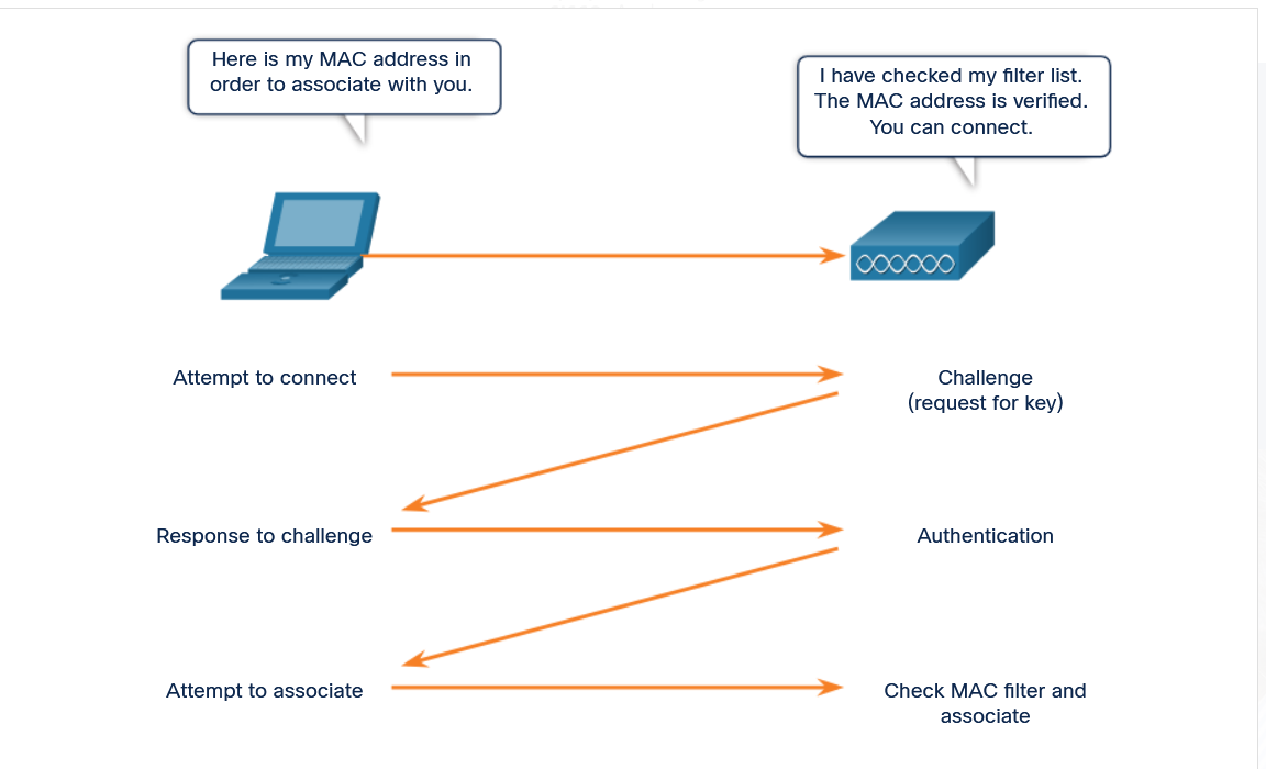
12 |
--------------------------------------------------------------------------------
/01. Internet Connection/6. Online Connections/2. Local Network Connections/3. Manual & Automatic Address Assignment/README.md:
--------------------------------------------------------------------------------
1 | # Manual IP Configuration
2 |
3 | - With manual configuration, the required values are entered into the device via the keyboard, typically by a network administrator.
4 | - The IP address that is entered is referred to as a static address and and must be unique on the network.
5 |
6 | # Dynamic IP Configuration
7 |
8 | - Most end-user devices can be set up to receive network configuration information dynamically.
9 | - This enables the device to request an address from a pool of addresses assigned by a Dynamic Host Configuration Protocol (DHCP) server located within the network.
10 |
11 | 
12 |
--------------------------------------------------------------------------------
/02. Build a Simple Network/1. Network Media Types/README.md:
--------------------------------------------------------------------------------
1 | # The 3 Media Types
2 |
3 | - Modern networks primarily use three types of media to interconnect devices, as shown in the figure:
4 | - **Metal wires within cables -** Data is encoded into electrical impulses.
5 | - **Glass or plastic fibers within cables (fiber-optic cable) -** Data is encoded into pulses of light.
6 | - **Wireless transmission -** Data is encoded via modulation of specific frequencies of electromagnetic waves.
7 |
8 | ## The 4 main criteria for choosing network media are these:
9 |
10 | What is the maximum distance that the media can successfully carry a signal?
11 | What is the environment in which the media will be installed?
12 | What is the amount of data and at what speed must it be transmitted?
13 | What is the cost of the media and installation?
14 |
--------------------------------------------------------------------------------
/02. Build a Simple Network/7. Simple Network Using Cisco Packet Tracer/1. The ping Command/README.md:
--------------------------------------------------------------------------------
1 | # The ping
2 |
3 | - The `ping` utility tests end-to-end connectivity between the IP address of the source of the message and the IP address of its destination.
4 | - It measures the time that it takes test messages to make a round trip from the source to the destination, and whether the transmission is successful.
5 | - However, if the test message does not reach the destination, or if delays are encountered along the way, there is no way to determine where the problem is located.
6 | - The format of the ping command is universally implemented.
7 | - Almost all network attached devices provide a way to perform a ping test.
8 | - The format of the ping command is ping x.x.x.x, where x.x.x.x is an IP address or domain name:
9 |
10 | For example, `ping 192.168.30.1`
11 |
--------------------------------------------------------------------------------
/01. Internet Connection/4. Clients & Servers/3. Peer-to-Peer Applications/README.md:
--------------------------------------------------------------------------------
1 | # Peer-to-Peer Applications
2 |
3 | - A P2P application allows a device to act as both a client and a server within the same communication, as shown in the figure.
4 | - In this model, every client is a server and every server is a client.
5 | - P2P applications require that each end device provide a user interface and run a background service.
6 |
7 | 
8 |
9 | - Both clients can simultaneously send and receive messages.
10 | - Some P2P applications use a hybrid system where resource sharing is decentralized, but the indexes that point to resource locations are stored in a centralized directory.
11 | - In a hybrid system, each peer accesses an index server to get the location of a resource stored on another peer.
12 |
--------------------------------------------------------------------------------
/01. Internet Connection/4. Clients & Servers/4. Multiple Roles in a Network/README.md:
--------------------------------------------------------------------------------
1 | # Multiple Roles in a Network
2 |
3 | - A computer with server software can provide services simultaneously to one or many clients, as shown in the figure.
4 |
5 | 
6 |
7 | - Additionally, a single computer can run multiple types of server software. In a home or small business, it may be necessary for one computer to act as a file server, a web server, and an email server.
8 | - A single computer can also run multiple types of client software.
9 | - There must be client software for every service required.
10 | - With multiple clients installed, a host can connect to multiple servers at the same time.
11 | - For example, a user can check email and view a web page while instant messaging and listening to internet radio.
12 |
--------------------------------------------------------------------------------
/02. Build a Simple Network/3. Ethernet Cabling/1. Twisted-Pair Cables/README.md:
--------------------------------------------------------------------------------
1 | # Twisted-Pair Cables
2 |
3 | - Twisted-pair cables consist of one or more pairs of insulated copper wires that are twisted together and housed in a protective jacket.
4 | - Like all copper cables, twisted-pair uses pulses of electricity to transmit data.
5 | - Data transmission over copper cable is sensitive to electromagnetic interference (EMI), which can reduce the data throughput rate that a cable can provide.
6 | - Another source of interference, known as `crosstalk`, occurs when cables are bundled together for long lengths.
7 | - The electrical impulses from one cable can cross over to an adjacent cable. This occurs most frequently when cables are improperly installed and terminated.
8 | - When data transmission is corrupted due to interference such as crosstalk, the data must be retransmitted. This can degrade the data carrying capacity of the medium.
9 |
--------------------------------------------------------------------------------
/03. Network Protocols and Architecture/1. Communication Principles/1. The Rules/2. Communication Protocols/README.md:
--------------------------------------------------------------------------------
1 | # Communication Protocols
2 |
3 | - Before beginning to communicate with each other, we establish rules or agreements to govern the conversation.
4 | - These agreements include the following:
5 |
6 | - What method of communication should we use?
7 | - What language should we use?
8 | - Do we need to confirm that our messages are received?
9 |
10 | - These rules, or protocols, must be followed in order for the message to be successfully delivered and understood.
11 | - Among the protocols that govern successful human communication are these:
12 |
13 | - An identified sender and receiver
14 | - Agreed upon method of communicating (face-to-face, telephone, letter, photograph)
15 | - Common language and grammar
16 | - Speed and timing of delivery
17 | - Confirmation or acknowledgment requirements
18 |
--------------------------------------------------------------------------------
/06. Connecting to Internet/2. Network Virtualization/10. SDN Architecture/README.md:
--------------------------------------------------------------------------------
1 | # SDN Architecture
2 |
3 | - In a traditional router or switch architecture, the control plane and data plane functions occur in the same device.
4 |
5 | - Routing decisions and packet forwarding are the responsibility of the device operating system.
6 | - In SDN, management of the control plane is moved to a centralized SDN controller.
7 |
8 | - The figure compares traditional and SDN architectures.
9 |
10 |
11 | 
12 |
13 | - The SDN controller is a logical entity that enables network administrators to manage and dictate how the data plane of switches and routers should handle network traffic.
14 |
15 | - It typically runs on a server.
16 | - It orchestrates, mediates, and facilitates communication between applications and network elements.
17 |
--------------------------------------------------------------------------------
/03. Network Protocols and Architecture/1. Communication Principles/4. Ethernet/3. Ethernet MAC Address/README.md:
--------------------------------------------------------------------------------
1 | # Ethernet MAC Address
2 |
3 | - All communication requires a way to identify the source and destination.
4 | - The source and destination in human communication are represented by names.
5 |
6 | - When your name is called, you listen to the message and respond.
7 | - Other people in the room may hear the message, but they ignore it because it is not addressed to them.
8 |
9 | - On Ethernet networks, a similar method exists for identifying source and destination hosts.
10 | - Each host connected to an Ethernet network is assigned a physical address which serves to identify the host on the network.
11 |
12 | - Every Ethernet network interface has a physical address assigned to it when it is manufactured.
13 | - This address is known as the Media Access Control (MAC) address.
14 | - The MAC address identifies each source and destination host on the network.
15 |
--------------------------------------------------------------------------------
/07. Network and Device Security/5. Antimalware Software/4. Antispyware Software/README.md:
--------------------------------------------------------------------------------
1 | # Antispyware Software
2 |
3 | ## Antispyware and Adware
4 |
5 | - Spyware and adware can also cause virus-like symptoms.
6 | - In addition to collecting unauthorized information, they can use important computer resources and affect performance.
7 | - Antispyware software detects and deletes spyware applications, as well as prevents future installations from occurring.
8 | - Many antispyware applications also include detection and deletion of cookies and adware.
9 |
10 | - Some antivirus packages include antispyware functionality.
11 |
12 | ## Popoup Blockers
13 |
14 | - Popup blocking software can be installed to prevent popups and pop-unders.
15 | - Many web browsers include a popup blocker feature by default.
16 | - Note that some programs and web pages create necessary and desirable popups.
17 |
18 | - Most popup blockers offer an override feature for this purpose.
19 |
--------------------------------------------------------------------------------
/04. Data Communications and Network Services/4. Application Layer Services/2. Domain Name System/2. DNS Servers/README.md:
--------------------------------------------------------------------------------
1 | # DNS Servers
2 |
3 | - A DNS server contains a table that associates hostnames in a domain with corresponding IP addresses.
4 | - When a client has the name of server, such as a web server, but needs to find the IP address, it sends a request to the DNS server on port 53.
5 | - The client uses the IP address of the DNS server configured in the DNS settings of the host IP configuration.
6 | - When the DNS server receives the request, it checks its table to determine the IP address associated with that web server.
7 | - If the local DNS server does not have an entry for the requested name, it queries another DNS server within the domain.
8 | - When the DNS server learns the IP address, that information is sent back to the client.
9 | - If the DNS server cannot determine the IP address, the request will time out and the client will not be able to communicate with the web server.
10 |
--------------------------------------------------------------------------------
/03. Network Protocols and Architecture/3. Routing Between Networks/2. The Routing Table/2. Packet Forwarding/README.md:
--------------------------------------------------------------------------------
1 | # Packet Forwarding
2 |
3 | - A router forwards a packet to one of two places: a directly connected network containing the actual destination host, or to another router on the path to reach the destination host.
4 | - When a router encapsulates the frame to forward it out an Ethernet interface, it must include a destination MAC address.
5 | - This is the MAC address of the actual destination host, if the destination host is part of a network that is locally connected to the router.
6 | - If the router must forward the packet to another router through an Ethernet interface, it will use the MAC address of the connected router. Routers obtain these MAC addresses from ARP tables.
7 | - Each router interface is part of the local network to which it is attached and maintains its own ARP table for that network.
8 | - The ARP tables contain the MAC addresses and IPv4 addresses of all the individual hosts on that network.
9 |
--------------------------------------------------------------------------------
/09. Intro to Cisco Networking/4. Troubleshooting Common Network Problems/1. The Troubleshooting Process/2. Gather Information/README.md:
--------------------------------------------------------------------------------
1 | # Gather Information
2 |
3 | - When a problem is first discovered in the network, it is important to verify it and determine how much of the network is affected by it.
4 |
5 | - After the problem is confirmed, the first step in troubleshooting is to gather information.
6 |
7 | - The following checklist provides some of the important information you should check.
8 |
9 | #
10 | **1. Nature of problem**
11 |
12 | End-user reports
13 | Problem verification report
14 |
15 | **2. Equipment**
16 |
17 | Manufacturer
18 | Make / model
19 | Firmware version
20 | Operating system version
21 | Ownership / warranty information
22 |
23 | **3. Configuration and Topology**
24 |
25 | Physical and logical topology
26 | Configuration files
27 | Log files
28 |
29 | **4. Previous Troubleshooting**
30 |
31 | Steps taken
32 | Results achieved
33 |
--------------------------------------------------------------------------------
/07. Network and Device Security/3. Malware/1. Malicious Software/README.md:
--------------------------------------------------------------------------------
1 | # Malicious Software
2 |
3 | - In addition to social engineering, there are other types of attacks launched by malicious software which exploit the vulnerabilities in computer software.
4 | - Malware is the short name for malicious software.
5 |
6 | - Examples of malware attacks include viruses, worms, and Trojan horses.
7 | - All of these are types of malware introduced onto a host.
8 | - They can damage a system, destroy data, as well as deny access to networks, systems, or services.
9 | - They can also forward data and personal details from unsuspecting PC users to criminals.
10 | - In many cases, they can replicate themselves and spread to other hosts connected to the network.
11 | - Imagine how difficult it would be to recreate saved files, such as game files, license key files, photographs, and videos.
12 |
13 | - Sometimes these techniques are used in combination with social engineering to trick an unsuspecting user into executing the attack.
14 |
15 |
--------------------------------------------------------------------------------
/04. Data Communications and Network Services/3. Transport Layer Services/3. Port Numbers/4. The netstat Command/README.md:
--------------------------------------------------------------------------------
1 | # The netstat Command
2 |
3 | - Unexplained TCP connections can pose a major security threat.
4 | - They can indicate that something or someone is connected to the local host.
5 | - Sometimes it is necessary to know which active TCP connections are open and running on a networked host.
6 | - Netstat is an important network utility that can be used to verify those connections.
7 | - As shown below, enter the command netstat to list the protocols in use, the local address and port numbers, the foreign address and port numbers, and the connection state.
8 |
9 | 
10 |
11 | - By default, the netstat command will attempt to resolve IP addresses to domain names and port numbers to well-known applications.
12 | - The -n option can be used to display IP addresses and port numbers in their numerical form.
13 |
--------------------------------------------------------------------------------
/01. Internet Connection/1. Communications in a Connected World/3. Home Devices/README.md:
--------------------------------------------------------------------------------
1 | # Home Devices
2 |
3 | ## **1. Security System**
4 |
5 | - Many of the items in a home, such as security systems, lighting, and climate controls, can be monitored and configured remotely using a mobile device.
6 |
7 | ## **2. Appliances**
8 |
9 | - Household appliances such as refrigerators, ovens, and dishwashers can be connected to the Internet. This allows the homeowner to power them on or off, monitor the status of the appliance, and also be alerted to preset conditions, such as when the temperature in the refrigerator rises above an acceptable level.
10 |
11 | ## 3. Smart TV
12 |
13 | - A smart TV can be connected to the Internet to access content without the need for TV service provider equipment. Also, a smart TV can allow a user to browse the web, compose email, or display video, audio, or photos stored on a computer.
14 |
15 | ## 4. Gaming Console
16 |
17 | - Gaming consoles can connect to the internet to download games and play with friends online.
18 |
--------------------------------------------------------------------------------
/03. Network Protocols and Architecture/2. Network Design & the Access Layer/4. Broadcast Containment/3. Access Layer Communication/README.md:
--------------------------------------------------------------------------------
1 | # Access Layer Communication
2 |
3 | - On a local Ethernet network, a NIC only accepts a frame if the destination address is either the broadcast MAC address, or else corresponds to the MAC address of the NIC.
4 | - Most network applications, however, rely on the logical destination IP address to identify the location of the servers and clients.
5 | - The figure illustrates the problem that arises if a sending host only has the logical IP address of the destination host.
6 | - How does the sending host determine what destination MAC address to place within the frame?
7 | - The sending host can use an IPv4 protocol called address resolution protocol (ARP) to discover the MAC address of any host on the same local network.
8 | - IPv6 uses a similar method known as Neighbor Discovery.
9 |
10 | 
11 |
12 |
--------------------------------------------------------------------------------
/04. Data Communications and Network Services/4. Application Layer Services/6. Email and Messaging/1. Email Clients and Server/README.md:
--------------------------------------------------------------------------------
1 | # Email Clients and Servers
2 |
3 | - Email is one of the most popular client/server applications on the internet.
4 | - Email servers run server software that enables them to interact with clients and with other email servers over the network.
5 |
6 | - Each mail server receives and stores mail for users who have mailboxes configured on the mail server.
7 | - Each user with a mailbox must then use an email client to access the mail server and read these messages.
8 | - Many internet messaging systems use a web-based client to access email.
9 | - Examples of this type of client include Microsoft 365, Yahoo, and Gmail.
10 |
11 | - Mailboxes are identified by the format: user@company.domain
12 |
13 | - Various application protocols used in processing email include SMTP, POP3, and IMAP4.
14 |
15 | 
16 |
--------------------------------------------------------------------------------
/09. Intro to Cisco Networking/3. Cisco Routers/1. Router Components/README.md:
--------------------------------------------------------------------------------
1 | # Router Components
2 |
3 | - Regardless of their function, size, or complexity, all router models are essentially computers. Just like computers, tablets, and smart devices, routers also require the following:
4 |
5 | - Operating system **(OS)**
6 | - Central processing unit **(CPU)**
7 | - Random-access memory **(RAM)**
8 | - Read-only memory **(ROM)**
9 | - Nonvolatile random-access memory **(NVRAM)**
10 |
11 | - Like all computers, tablets, and smart devices, Cisco routers require a CPU to execute OS instructions, such as system initialization, routing functions, and switching functions.
12 |
13 | - The CPU requires an OS to provide routing and switching functions.
14 | - The Cisco Internetwork Operating System (IOS) is the system software used for most Cisco devices, regardless of the size and type of the device.
15 | - It is used for routers, LAN switches, small wireless access points, large routers with dozens of interfaces, and many other devices.
16 |
--------------------------------------------------------------------------------
/03. Network Protocols and Architecture/4. The Internet Protocol/3. IPv4 Address Structure/2. Logical AND/README.md:
--------------------------------------------------------------------------------
1 | # Logical AND
2 |
3 | - A logical AND is one of three basic binary operations used in digital logic.
4 | - The other two are OR and NOT.
5 | - Although all three are used in data networks, only AND is used in determining the network address.
6 | - Therefore, our discussion here will be limited to the logical AND operation.
7 | - To identify the network address of an IPv4 host, the IPv4 address is logically ANDed, bit by bit, with the subnet mask.
8 | - ANDing between the address and the subnet mask yields the network address.
9 | - To illustrate how AND is used to discover a network address, consider a host with IPv4 address 192.168.10.10 and subnet mask of 255.255.255.0.
10 | - The following figure displays the host IPv4 address and converted binary address.
11 | - The host subnet mask binary address is ANDed.
12 |
13 | 
14 |
15 |
--------------------------------------------------------------------------------
/07. Network and Device Security/5. Antimalware Software/3. Antispam Software/README.md:
--------------------------------------------------------------------------------
1 | # Antispam Software
2 |
3 | - No one likes opening their email and being overwhelmed by unwanted messages.
4 | - Spam is not only annoying; it can overload email servers and potentially carry viruses and other security threats.
5 | - Additionally, people who send spam may use links within the emails to take control of a host by planting code on it in the form of a virus or a Trojan horse.
6 | - The host is then used to send spam mail without the knowledge of the user, consuming the local bandwidth and processor resources.
7 |
8 | - Antispam software protects hosts by identifying spam and performing an action, such as placing it into a junk folder or deleting it.
9 | - Spam filters can be loaded on individual devices, but can also be loaded on email servers.
10 | - In addition, many ISPs offer spam filters.
11 | - Antispam software does not recognize all spam, so it is important to open email carefully.
12 | - It may also accidentally identify wanted email as spam and treat it as such.
13 |
--------------------------------------------------------------------------------
/08. Security Configuration/1. Wireless Security Measures/4. Changing Default Settings/README.md:
--------------------------------------------------------------------------------
1 | # Changing Default Settings
2 |
3 | - What are default settings and why are they there?
4 | - Most wireless access points and routers are preconfigured with settings such as SSIDs, administrator passwords, and IP addresses.
5 | - These settings make it easier for the novice user to set up and configure the device in the home LAN environment.
6 | - Unfortunately, these defaults can also make it easy for an attacker to identify and infiltrate a network.
7 |
8 | - Changing the default settings on a wireless router will not protect your network by itself.
9 | - For example, SSIDs are transmitted in plaintext.
10 | - There are devices that will intercept wireless signals and read plaintext messages.
11 | - Even with SSID broadcast turned off and default values changed, attackers can learn the name of a wireless network through the use of these devices that intercept wireless signals.
12 | - This information will be used to connect to the network.
13 | - It takes a combination of several methods to protect your WLAN.
14 |
--------------------------------------------------------------------------------
/09. Intro to Cisco Networking/4. Troubleshooting Common Network Problems/1. The Troubleshooting Process/1. Overview/README.md:
--------------------------------------------------------------------------------
1 | # Troubleshooting Overview
2 |
3 | - Troubleshooting is the process of identifying, locating and correcting problems.
4 |
5 | - Experienced individuals often rely on instinct to troubleshoot.
6 |
7 | - However, there are structured techniques that can be used to determine the most probable cause and solution.
8 |
9 | - When troubleshooting, proper documentation must be maintained.
10 |
11 | - This documentation should include as much information as possible about the following:
12 |
13 | - The problem encountered
14 | - Steps taken to determine the cause of the problem
15 | - Steps to correct the problem and ensure that it will not reoccur
16 |
17 | - Document all steps taken in troubleshooting, even the ones that did not solve the issue.
18 |
19 | - This documentation becomes a valuable reference should the same or similar problem occur again.
20 |
21 | - Even in a small home network, good documentation saves hours of trying to remember how a problem was fixed in the past.
22 |
--------------------------------------------------------------------------------
/04. Data Communications and Network Services/4. Application Layer Services/2. Domain Name System/1. Domain Name Translation/README.md:
--------------------------------------------------------------------------------
1 | # Domain Name Translation
2 |
3 | - Thousands of servers, installed in many different locations, provide the services that we use daily over the internet.
4 | - Each of these servers is assigned a unique IP address that identifies it on the local network where it is connected.
5 | - It would be impossible to remember all of the IP addresses for all of the servers hosting services on the internet.
6 | - Instead, there is an easier way to locate servers by associating a name with an IP address.
7 | - The Domain Name System (DNS) provides a way for hosts to use this name to request the IP address of a specific server, as shown in the figure.
8 | - DNS names are registered and organized on the internet within specific high level groups, or domains.
9 | - Some of the most common high level domains on the internet are .com, .edu, and .net.
10 |
11 | 
12 |
13 |
14 |
15 |
--------------------------------------------------------------------------------
/02. Build a Simple Network/4. Co-axial Cabling/README.md:
--------------------------------------------------------------------------------
1 | # Cable TV and Satellite Cables
2 |
3 | - Like twisted-pair, coaxial cable (or coax) carries data in the form of electrical signals. It provides improved shielding compared to UTP and can therefore carry more data.
4 | - Coaxial cable is usually constructed of either copper or aluminum.
5 | - It is used by cable television companies to provide service and for connecting the various components that make up satellite communication systems.
6 | - You are probably familiar with the coaxial cables used to connect a TV set to the signal source, be it a cable TV outlet, satellite TV, or conventional antenna in your home.
7 | - With the addition of a cable modem, the cable television provider can offer data and internet service, as well as television signals and telephone over the same coaxial cable.
8 | - Although coax has improved data carrying characteristics, twisted-pair cabling has replaced coax in local area networking uses.
9 | - Among the reasons for the replacement is that compared to UTP, coax is physically harder to install, more expensive, and harder to troubleshoot.
10 |
--------------------------------------------------------------------------------
/06. Connecting to Internet/2. Network Virtualization/7. Network Virtualization/README.md:
--------------------------------------------------------------------------------
1 | # Network Virtualization
2 |
3 | - Virtualization separates the operating system (OS) from the hardware.
4 |
5 | - Server virtualization takes advantage of idle resources and consolidates the number of required servers.
6 | - This also allows for multiple operating systems to exist on a single hardware platform.
7 |
8 | - For example, in the figure, the previous eight dedicated servers have been consolidated into two servers using hypervisors to support multiple virtual instances of the operating systems.
9 |
10 | ### Hypervisor OS Installation
11 |
12 | 
13 |
14 | - Network virtualization combines traditional networking hardware and software network resources into a software-based entity, which is a virtual network.
15 | - Could the network infrastructure also benefit from virtualization?
16 | - If so, then how?
17 | - The answer is found in how a networking device operates using a data plane and a control plane.
18 |
--------------------------------------------------------------------------------
/06. Connecting to Internet/2. Network Virtualization/9. Network Virtualization and SDN/README.md:
--------------------------------------------------------------------------------
1 | # Network Virtualization and SDN
2 |
3 | - Network virtualization combines networking hardware and software network resources into a software-based entity which is a virtual network.
4 |
5 | - Software-Defined Networking (SDN) is a network architecture that virtualizes the network, offering a new approach to network administration and management that seeks to simplify and streamline the administration process
6 |
7 | - SDN is basically the separation of the control plane and data plane.
8 | - The control plane function is removed from each device and is performed by a centralized controller, as shown in the figure.
9 |
10 | - The centralized controller communicates control plane functions to each device.
11 | - Each device can now focus on forwarding data while the centralized controller manages data flow, increases security, and provides other services.
12 |
13 | ## Centralized Control Plane
14 |
15 | 
16 |
--------------------------------------------------------------------------------
/08. Security Configuration/3. Configure a Firewall/4. Port Forwarding/README.md:
--------------------------------------------------------------------------------
1 | # Port Forwarding
2 |
3 | - One of the ways that you can permit other users to reach devices on your network through the internet is a function called port forwarding.
4 | - Port forwarding is a rule-based method of directing traffic between devices on separate networks.
5 |
6 | - This method of exposing your devices to the internet is much safer than using a DMZ.
7 |
8 | - When incoming traffic from the internet reaches your router, the firewall in the router determines if the traffic should be forwarded to a certain device based on the port number found with the traffic.
9 | - Port numbers are associated with specific services, such as FTP, HTTP, HTTPS, and POP3.
10 | - The rules that you configure in the firewall settings determine which traffic is permitted on to the LAN.
11 | - For example, a router might be configured to forward port 80, which is associated with HTTP.
12 |
13 | - When the router receives a packet with the destination port of 80, the router forwards the traffic to the device inside the network that serves web pages.
14 |
--------------------------------------------------------------------------------
/04. Data Communications and Network Services/3. Transport Layer Services/2. TCP and UDP/2. TCP & UDP/README.md:
--------------------------------------------------------------------------------
1 | # TCP & UDP
2 |
3 | - Each service available over the network has its own application protocols that are implemented in the server and client software.
4 | - In addition to the application protocols, all of the common internet services use Internet Protocol (IP) to address and route messages between source and destination hosts, as shown in the figure.
5 | - IP is concerned only with the structure, addressing, and routing of packets.
6 | - IP does not specify how the delivery or transportation of the packets takes place.
7 | - The application decides which transport protocol to use.
8 | - Transport protocols specify how to manage the transfer of messages between hosts.
9 | - The two most common transport protocols are Transmission Control Protocol (TCP) and User Datagram Protocol (UDP).
10 | - The IP protocol uses these transport protocols to enable hosts to communicate and transfer data.
11 |
12 | 
13 |
--------------------------------------------------------------------------------
/05. Home Network Basics/3. Wireless Standards/2. Wireless Settings/README.md:
--------------------------------------------------------------------------------
1 | # Wireless Settings
2 |
3 | The Packet Tracer Basic Wireless Settings interface is shown in the figure. Wireless routers using the `802.11 standards` have multiple settings that have to be configured.\
4 | These settings include the following:
5 |
6 | 1. Network mode - Determines the type of technology that must be supported.
7 | For example, 802.11b, 802.11g, 802.11n or Mixed Mode.
8 | 2. Network Name (SSID) - Used to identify the WLAN. All devices that wish to participate in the WLAN must have the same SSID.
9 | 3. Standard Channel - Specifies the channel over which communication will occur.
10 | By default, this is set to Auto to allow the AP to determine the optimum channel to use.
11 | 4. SSID Broadcast - Determines if the SSID will be broadcast to all devices within range. By default, set to Enabled.
12 |
13 | - Note: SSID stands for Service Set Identifier.
14 |
15 | 
16 |
--------------------------------------------------------------------------------
/08. Security Configuration/1. Wireless Security Measures/5. MAC Address Filtering/README.md:
--------------------------------------------------------------------------------
1 | # MAC Address Filtering
2 |
3 | - One way to limit access to the wireless network is to control exactly which devices are allowed on the wireless network (or on some routers/APs the configuration is what devices are not allowed) by filtering MAC addresses.
4 | - If MAC address filtering is configured for devices that are allowed on the network, when a wireless client attempts to connect, or associate, with an AP it will send MAC address information.
5 | - The wireless router or AP will look up the MAC address of the connecting client and permit or allow the device onto the wireless network based on the configuration.
6 |
7 | - There are some issues with this type of security.
8 | - The person setting up the wireless router/AP will have to enter MAC addresses, so this measure does not scale well.
9 | - Additionally, it is possible for an attacking device to clone the MAC address of another device that has access.
10 |
11 |
12 | 
13 |
--------------------------------------------------------------------------------
/LICENSE:
--------------------------------------------------------------------------------
1 | MIT License
2 |
3 | Copyright (c) 2022 ShubhamJagtap2000
4 |
5 | Permission is hereby granted, free of charge, to any person obtaining a copy
6 | of this software and associated documentation files (the "Software"), to deal
7 | in the Software without restriction, including without limitation the rights
8 | to use, copy, modify, merge, publish, distribute, sublicense, and/or sell
9 | copies of the Software, and to permit persons to whom the Software is
10 | furnished to do so, subject to the following conditions:
11 |
12 | The above copyright notice and this permission notice shall be included in all
13 | copies or substantial portions of the Software.
14 |
15 | THE SOFTWARE IS PROVIDED "AS IS", WITHOUT WARRANTY OF ANY KIND, EXPRESS OR
16 | IMPLIED, INCLUDING BUT NOT LIMITED TO THE WARRANTIES OF MERCHANTABILITY,
17 | FITNESS FOR A PARTICULAR PURPOSE AND NONINFRINGEMENT. IN NO EVENT SHALL THE
18 | AUTHORS OR COPYRIGHT HOLDERS BE LIABLE FOR ANY CLAIM, DAMAGES OR OTHER
19 | LIABILITY, WHETHER IN AN ACTION OF CONTRACT, TORT OR OTHERWISE, ARISING FROM,
20 | OUT OF OR IN CONNECTION WITH THE SOFTWARE OR THE USE OR OTHER DEALINGS IN THE
21 | SOFTWARE.
22 |
--------------------------------------------------------------------------------
/03. Network Protocols and Architecture/2. Network Design & the Access Layer/3. The Access Layer & Devices/1. Access Layer/README.md:
--------------------------------------------------------------------------------
1 | # The Access Layer
2 |
3 | - The access layer is the basic level of the network.
4 | - It is the part of the network in which people gain access to other hosts and to shared files and printers.
5 | - The access layer provides the first line of networking devices that connect hosts to the wired Ethernet network.
6 | - Networking devices enable us to connect many hosts with each other and also provide those hosts access to services offered over the network.
7 | - Unlike the simple network consisting of two hosts connected by a single cable, in the access layer, each host is connected to a networking device.
8 | - Within an Ethernet network, each host is able to connect directly to an access layer networking device using an Ethernet cable.
9 | - These cables are manufactured to meet specific Ethernet standards.
10 | - Each cable is plugged into a host NIC and then into a port on the networking device.
11 | - There are several types of networking devices that can be used to connect hosts at the access layer, including Ethernet switches.
12 |
--------------------------------------------------------------------------------
/04. Data Communications and Network Services/4. Application Layer Services/3. Web Clients and Servers/1. HTTP and HTML/README.md:
--------------------------------------------------------------------------------
1 | # HTTP and HTML
2 |
3 | - When a web client receives the IP address of a web server, the client browser uses that IP address and port 80 to request web services.
4 | - This request is sent to the server using the Hypertext Transfer Protocol (HTTP).
5 |
6 | - When the server receives a port 80 request, the server responds to the client request and sends the web page to the client.
7 | - The information content of a web page is encoded using specialized 'mark-up' languages.
8 | - The HyperText Markup Language (HTML) coding tells the browser how to format the web page and what graphics and fonts to use.
9 | - HTML is the most commonly used language.
10 |
11 | - The HTTP protocol is not a secure protocol; information could easily be intercepted by other users as data is sent over the network.
12 | - In order to provide security for the data, HTTP can be used with secure transport protocols.
13 | - Requests for secure HTTP are sent to port 443.
14 | - These requests use https in the site address in the browser, rather than HTTP.
15 |
16 |
--------------------------------------------------------------------------------
/07. Network and Device Security/2. Social Engineering Attacks/1. Overview/README.md:
--------------------------------------------------------------------------------
1 | # Overview of Social Engineering
2 |
3 | - One of the easiest ways for an intruder to gain access, whether internal or external, is by exploiting human behavior.
4 | - One of the more common methods of exploiting human weaknesses is called social engineering.
5 |
6 | - Social engineering is a term that refers to the ability of something or someone to influence the behavior of a person or group of people.
7 | - In the context of computer and network security, social engineering refers to a collection of techniques used to deceive internal users into performing specific actions or revealing confidential information.
8 |
9 | - With these techniques, the attacker takes advantage of unsuspecting legitimate users to gain access to internal resources and private information, such as bank account numbers or passwords.
10 |
11 | - Social engineering attacks exploit the fact that users are generally considered one of the weakest links in security.
12 | - Social engineers can be internal or external to the organization, but most often do not come face-to-face with their victims.
13 |
14 |
--------------------------------------------------------------------------------
/01. Internet Connection/6. Online Connections/4. Network Documentation/2. Logical Network Information/README.md:
--------------------------------------------------------------------------------
1 | # Logical Network Information
2 |
3 | - Documenting the physical connections and devices in your network will provide you with the information that you need to know when connecting new devices or finding problems with broken connectivity.
4 | - But there is other information that you must have when troubleshooting network problems. This information cannot be “seen” from the physical view of the network.
5 | - The device names, IP addressing, configuration information, and network designations are logical pieces of information that may change more frequently than the physical connectivity.
6 | - A diagram called a logical topology illustrates the relevant network configuration information.
7 |
8 | ## Physical Topology
9 |
10 | 
11 |
12 | ## Logical Topology
13 |
14 | 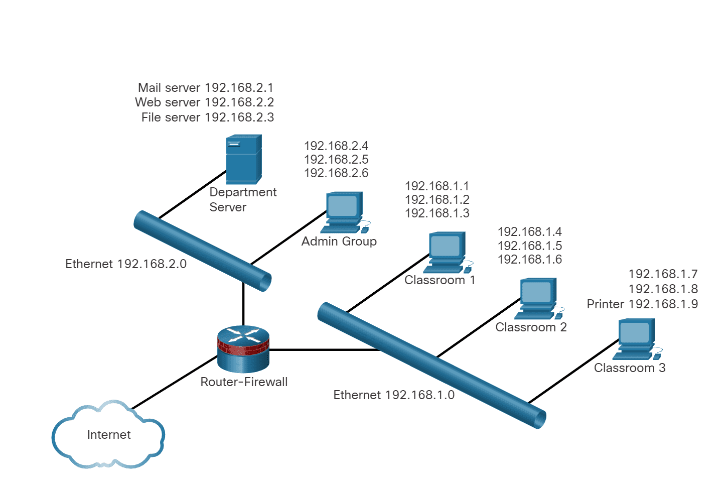
15 |
16 |
--------------------------------------------------------------------------------
/03. Network Protocols and Architecture/2. Network Design & the Access Layer/4. Broadcast Containment/4. Address Resolution Protocol/README.md:
--------------------------------------------------------------------------------
1 | # The ARP
2 |
3 | - ARP uses a three step process to discover and store the MAC address of a host on the local network when only the IPv4 address of the host is known:
4 |
5 | 1. The sending host creates and sends a frame addressed to a broadcast MAC address. Contained in the frame is a message with the IPv4 address of the intended destination host.
6 | 2. Each host on the network receives the broadcast frame and compares the IPv4 address inside the message with its configured IPv4 address. The host with the matching IPv4 address sends its MAC address back to the original sending host.
7 | 3. The sending host receives the message and stores the MAC address and IPv4 address information in a table called an ARP table.
8 |
9 | - When the sending host has the MAC address of the destination host in its ARP table, it can send frames directly to the destination without doing an ARP request.
10 | - Because ARP messages rely on broadcast frames to deliver the requests, all hosts in the local IPv4 network must be in the same broadcast domain.
11 |
12 |
13 |
--------------------------------------------------------------------------------
/03. Network Protocols and Architecture/4. The Internet Protocol/6. Unicast, Broadcast and Multicast Addresses/1. Unicast Transmission/README.md:
--------------------------------------------------------------------------------
1 | # Unicast Transmission
2 |
3 | - Unicast communication is used for normal host-to-host communication in both a client/server and a peer-to-peer network.
4 | - Unicast packets use the address of the destination device as the destination address and can be routed through an internetwork.
5 | - In an IPv4 network, the unicast address applied to an end device is referred to as the host address.
6 | - For unicast communication, the addresses assigned to the two end devices are used as the source and destination IPv4 addresses.
7 | - During the encapsulation process, the source host uses its IPv4 address as the source address and the IPv4 address of the destination host as the destination address.
8 | - Regardless of whether the destination specified a packet as a unicast, broadcast or multicast; the source address of any packet is always the unicast address of the originating host.
9 | - IPv4 unicast host addresses are in the address range of 0.0.0.0 to 223.255.255.255.
10 | - However, within this range are many addresses that are reserved for special purposes.
11 |
--------------------------------------------------------------------------------
/05. Home Network Basics/4. Wireless Traffic Controls/1. Wireless Channels/README.md:
--------------------------------------------------------------------------------
1 | # Wireless Channels
2 |
3 | - Wireless devices that transmit over the same frequency range create interference in a Wi-Fi network.
4 | - Home electronic devices, such as cordless phones, other wireless networks, and baby monitors, may use this same frequency range.
5 | - These devices can slow down the Wi-Fi performance and potentially break network connections.
6 |
7 | - Channels are created by dividing up the available RF spectrum.
8 | - Each channel is capable of carrying a different conversation, as shown in the figure.
9 | - This is similar to the way that multiple television channels are transmitted across a single medium.
10 | - Multiple APs can function in close proximity to one another as long as they use different channels for communication.
11 | - Normally each wireless conversation makes use of a separate channel.
12 | - Some of the 5 GHz wireless technologies combine multiple channels to create a single wide channel, which provides more bandwidth and increases the data rate.
13 |
14 | 
15 |
--------------------------------------------------------------------------------
/03. Network Protocols and Architecture/2. Network Design & the Access Layer/3. The Access Layer & Devices/4. MAC Address Tables/README.md:
--------------------------------------------------------------------------------
1 | # The MAC Address Table
2 |
3 | - If the destination MAC address is not in the table, the switch does not have the necessary information to create an individual circuit.
4 | - When the switch cannot determine where the destination host is located, it uses a process called `flooding` to forward the message out to all attached hosts except for the sending host.
5 | - Each host compares the destination MAC address in the message to its own MAC address, but only the host with the correct destination address processes the message and responds to the sender.
6 |
7 | **How does the MAC address of a new host get into the MAC address table?**
8 |
9 | - A switch builds the MAC address table by examining the source MAC address of each frame that is sent between hosts.
10 | - When a new host sends a message or responds to a flooded message, the switch immediately learns its MAC address and the port to which it is connected.
11 | - The table is dynamically updated each time a new source MAC address is read by the switch.
12 | - In this way, a switch quickly learns the MAC addresses of all attached hosts.
13 |
--------------------------------------------------------------------------------
/03. Network Protocols and Architecture/2. Network Design & the Access Layer/4. Broadcast Containment/1. The Ethernet Broadcast/README.md:
--------------------------------------------------------------------------------
1 | # Ethernet Broadcast
2 |
3 | - Within the local network it is often necessary for one host to be able to send messages to all the other hosts at the same time.
4 | - This can be done using a message called `broadcast`.
5 | - Broadcasts are useful when a host needs to find information without knowing exactly what other host can supply it, or when a host wants to provide information to all other hosts in the same network in a timely manner.
6 | - A message can only contain one destination MAC address.
7 | - So, how is it possible for a host to contact every other host on the local network without sending out a separate message to each individual MAC?
8 | - To solve this problem, broadcast messages are sent to a unique MAC address that is recognized by all hosts.
9 | - The broadcast MAC address is actually a 48-bit address made up of all ones.
10 | - Because of their length, MAC addresses are usually represented in hexadecimal notation.
11 | - The broadcast MAC address in hexadecimal notation is FFFF.FFFF.FFFF.
12 | - Each F in the hexadecimal notation represents four ones in the binary address.
13 |
--------------------------------------------------------------------------------
/03. Network Protocols and Architecture/3. Routing Between Networks/3. Create a LAN/1. Local Area Networks/README.md:
--------------------------------------------------------------------------------
1 | # The LAN
2 |
3 | - The term local area network (LAN) refers to a local network, or a group of interconnected local networks that are under the same administrative control.
4 | - In the early days of networking, LANs were defined as small networks that existed in a single physical location.
5 | - Although LANs can be a single local network installed in a home or small office, the definition of LAN has evolved to include interconnected local networks consisting of many hundreds of hosts, installed in multiple buildings and locations.
6 | - The important thing to remember is that all the local networks within a LAN are under one administrative control.
7 | - Other common characteristics of LANs are that they typically use Ethernet or wireless protocols, and they support high data rates.
8 | - The term intranet is often used to refer to a private LAN that belongs to an organization, and is designed to be accessible only by the members of the organization, employees, or others with authorization.
9 |
10 | 
11 |
--------------------------------------------------------------------------------
/06. Connecting to Internet/2. Network Virtualization/8. Control Plane and Data Plane/README.md:
--------------------------------------------------------------------------------
1 | # Control Plane and Data Plane
2 |
3 | - A network device contains the following planes:
4 |
5 | **1. Control plane -** This is typically regarded as the brains of a device. It is used to make forwarding decisions. The control plane contains Layer 2 and Layer 3 route forwarding mechanisms, such as the IPv4 and IPv6 routing tables, and the ARP table. Information sent to the control plane is processed by the CPU.
6 |
7 | **2. Data plane -** Also called the forwarding plane, this plane is typically the switch fabric connecting the various network ports on a device. The data plane of each device is used to forward traffic flows. Routers and switches use information from the control plane to forward incoming traffic out the appropriate egress (outgoing) interface. Information in the data plane is typically processed by a special data plane processor without the CPU getting involved.
8 |
9 | - The figure illustrates how Cisco Express Forwarding (CEF) uses the control plane and data plane to process packets.
10 |
11 | 
12 |
--------------------------------------------------------------------------------
/05. Home Network Basics/2. Network Technologies in the Home/2. LAN Wireless Frequencies/README.md:
--------------------------------------------------------------------------------
1 | # LAN Wireless Frequencies
2 |
3 | - The wireless technologies most frequently used in home networks are in the unlicensed 2.4 GHz and 5 GHz frequency ranges.
4 |
5 | - Bluetooth is a technology that makes use of the 2.4 GHz band.
6 | - It is limited to low-speed, short-range communications, but has the advantage of communicating with many devices at the same time.
7 | - This one-to-many communication has made Bluetooth technology the preferred method for connecting computer peripherals such as wireless mice, keyboards and printers.
8 | - Bluetooth is a good method for transmitting audio to speakers or headphones.
9 |
10 | - Other technologies that use the 2.4 GHz and 5 GHz bands are the modern wireless LAN technologies that conform to the various IEEE 802.11 standards.
11 | - Unlike Bluetooth technology, 802.11 devices transmit at a much higher power level giving them a great range and improved throughput.
12 |
13 | - The figure shows where wireless technologies exist on the electromagnetic spectrum.
14 |
15 | 
16 |
17 |
18 |
--------------------------------------------------------------------------------
/04. Data Communications and Network Services/2. IPv4 and IPv6 Address Management/3. IPv4 Issues/2. IPv6 Address Size/README.md:
--------------------------------------------------------------------------------
1 | # IPv6 Address Size
2 |
3 | - IPv6 addressing will eventually replace IPv4 addressing, although both types of addresses will coexist for the foreseeable future.
4 | - IPv6 overcomes the limitations of IPv4 and has features that better suit current and foreseeable network demands.
5 | - The 32-bit IPv4 address space provides approximately 4,294,967,296 unique addresses.
6 | - IPv6 address space provides 340,282,366,920,938,463,463,374,607,431,768,211,456 addresses, or 340 undecillion addresses, which is roughly equivalent to the number of grains of sand on Earth.
7 | - The figure provides a visual to compare the IPv4 and IPv6 address space.
8 | - Other benefits of the IPv6 protocol include these:
9 |
10 | - No need for NAT. Each device can have its own globally routable address.
11 | - Autoconfiguration capabilities simplify address administration.
12 |
13 | - The designers of IPv6 thought that it would be adopted quickly, as the number of remaining available IPv4 address blocks was decreasing rapidly.
14 | - Initial estimates were that IPv6 would be globally deployed by 2003.
15 | - Obviously, these estimates were incorrect.
16 |
--------------------------------------------------------------------------------
/04. Data Communications and Network Services/3. Transport Layer Services/2. TCP and UDP/3. TCP Reliability/README.md:
--------------------------------------------------------------------------------
1 | # TCP Reliability
2 |
3 | - With all of the millions and millions of web pages being transmitted at any time over the internet, how can a server be certain that the page it sent is received by the client that requested it?
4 | - One of the mechanisms that helps ensure reliable delivery is the Transmission Control Protocol (TCP).
5 | - When an application requires acknowledgment that a message is delivered, it uses TCP.
6 | - TCP breaks up a message into small pieces known as segments.
7 | - The segments are numbered in sequence and passed to the IP process for assembly into packets.
8 | - TCP keeps track of the number of segments that have been sent to a specific host from a specific application.
9 | - If the sender does not receive an acknowledgment within a certain period of time, it assumes that the segments were lost and retransmits them.
10 | - Only the portion of the message that is lost is resent, not the entire message.
11 | - On the receiving host, TCP is responsible for reassembling the message segments and passing them to the application.
12 | - FTP and HTTP are examples of applications that use TCP to ensure delivery of data.
13 |
14 |
--------------------------------------------------------------------------------
/07. Network and Device Security/3. Malware/4. Adware and Popups/README.md:
--------------------------------------------------------------------------------
1 | ## Adware
2 |
3 | - Adware is a form of spyware that is used to collect information about a user based on websites the user visits.
4 | - That information is then used for targeted advertising.
5 | - Adware is commonly installed by a user in exchange for a "free" product.
6 | - When a user opens a browser window, adware can start new browser instances which attempt to advertise products or services based on the surfing practices of a user.
7 | - The unwanted browser windows can open repeatedly, and can make surfing the internet very difficult, especially with slow internet connections.
8 |
9 | - Adware can be very difficult to uninstall.
10 |
11 | ## Popups & Pop-unders
12 |
13 | - Popups and pop-unders are additional advertising windows that display when a website is visited. Unlike adware, popups and pop-unders are not intended to collect information about the user and are typically associated only with the website being visited.
14 |
15 | - **Popups:** These open in front of the current browser window.
16 |
17 | - **Pop-unders:** These open behind the current browser window.
18 |
19 | - They can be annoying and usually advertise products or services that are not wanted by the user.
20 |
--------------------------------------------------------------------------------
/06. Connecting to Internet/2. Network Virtualization/5. Advantages of Virtualization/README.md:
--------------------------------------------------------------------------------
1 | # Advantages of Virtualization
2 |
3 | ### Major Advantages
4 |
5 | - Overall reduced cost
6 | - Less equipment is required - Virtualization enables server consolidation, which requires fewer physical devices, lowers maintenance costs.
7 | - Less energy is consumed - Consolidating servers lowers the monthly power and cooling costs.
8 | - Less space is required - Server consolidation reduces the amount of required floor space.
9 |
10 | ### Additional Benefits
11 |
12 | - Easier prototyping - Self-contained labs, operating on isolated networks, can be rapidly created for testing and prototyping network deployments.
13 | - Faster server provisioning - Creating a virtual server is far faster than provisioning a physical server.
14 | - Increased server uptime - Most server virtualization platforms now offer advanced redundant fault tolerance features.
15 | - Improved disaster recovery - Most enterprise server virtualization platforms have software that can help test and automate failover before a disaster happens.
16 | - Legacy support - Virtualization can extend the life of OSs and applications providing more time for organizations to migrate to newer solutions.
17 |
--------------------------------------------------------------------------------
/03. Network Protocols and Architecture/4. The Internet Protocol/1. Purpose of the IPv4/README.md:
--------------------------------------------------------------------------------
1 | # Purpose of the IPv4 Address
2 |
3 | - A host needs an IPv4 address to participate on the internet and almost all LANs today.
4 | - The IPv4 address is a logical network address that identifies a particular host.
5 | - It must be properly configured and unique within the LAN, for local communication.
6 | - It must also be properly configured and unique in the world, for remote communication.
7 | - This is how a host is able to communicate with other devices on the internet.
8 | - An IPv4 address is assigned to the network interface connection for a host.
9 | - This connection is usually a network interface card (NIC) installed in the device.
10 | - Examples of end-user devices with network interfaces include workstations, servers, network printers, and IP phones.
11 | - Some servers can have more than one NIC and each of these has its own IPv4 address.
12 | - Router interfaces that provide connections to an IP network will also have an IPv4 address.
13 | - Every packet sent across the internet has a source and destination IPv4 address.
14 | - This information is required by networking devices to ensure the information gets to the destination and any replies are returned to the source.
15 |
16 |
17 |
--------------------------------------------------------------------------------
/05. Home Network Basics/3. Wireless Standards/1. Wi-Fi Networks/README.md:
--------------------------------------------------------------------------------
1 | # Wi-Fi Networks
2 |
3 | - A number of standards have been developed to ensure that wireless devices can communicate.
4 | - They specify the RF spectrum used, data rates, how the information is transmitted, and more.
5 | - The main organization responsible for the creation of wireless technical standards is the IEEE.
6 |
7 | - The IEEE 802.11 standard governs the WLAN environment.
8 | - There are amendments to the IEEE 802.11 standard that describe characteristics for different standards of wireless communications.
9 | - Wireless standards for LANs use the 2.4 GHz and 5 GHz frequency bands.
10 | - Collectively these technologies are referred to as Wi-Fi.
11 |
12 | - Another organization, known as the Wi-Fi Alliance, is responsible for testing wireless LAN devices from different manufacturers.
13 | - The Wi-Fi logo on a device means that this equipment meets standards and should operate with other devices that use the same standard.
14 |
15 | - Wireless standards are constantly improving the connectivity and speed of Wi-Fi networks.
16 | - It is important to be aware of new standards as they are introduced because manufacturers of wireless devices will implement these standards quickly in their new products.
17 |
18 |
--------------------------------------------------------------------------------
/03. Network Protocols and Architecture/2. Network Design & the Access Layer/4. Broadcast Containment/2. Broadcast Domain/README.md:
--------------------------------------------------------------------------------
1 | # Broadcast Domains
2 |
3 | - When a host receives a message addressed to the broadcast address, it accepts and processes the message as though the message was addressed directly to it.
4 | - When a host sends a broadcast message, switches forward the message to every connected host within the same local network.
5 | - For this reason, a local area network, a network with one or more Ethernet switches, is also referred to as a broadcast domain.
6 | - If too many hosts are connected to the same broadcast domain, broadcast traffic can become excessive.
7 | - The number of hosts and the amount of network traffic that can be supported on the local network is limited by the capabilities of the switches used to connect them.
8 | - As the network grows and more hosts are added, network traffic, including broadcast traffic, increases.
9 | - To improve performance, it is often necessary to divide one local network into multiple networks, or broadcast domains, as shown in the figure.
10 | - Routers are used to divide the network into multiple broadcast domains.
11 |
12 | 
13 |
14 |
--------------------------------------------------------------------------------
/05. Home Network Basics/2. Network Technologies in the Home/1. The EM Spectrum/README.md:
--------------------------------------------------------------------------------
1 | # Electromagnetic Spectrum
2 |
3 | - What would we do without wireless?
4 | - Because of the ever-increasing number of things that have the capability of connecting to the internet using wireless technologies, most home networks include some type of wireless network functionality.
5 |
6 | - Wireless technologies use electromagnetic waves to carry information between devices.
7 | - The electromagnetic spectrum includes such things as radio and television broadcast bands, visible light, x-rays and gamma-rays.
8 | - Each of these has a specific range of wavelengths and associated energies, as shown in the figure.
9 |
10 | - Some types of electromagnetic waves are not suitable for carrying data.
11 | - Other parts of the spectrum are regulated by governments and licensed to various organizations for specific applications.
12 | - Certain areas of the spectrum have been set aside to allow public use without the restriction of having to apply for special permits.
13 | - These unlicensed sections of the spectrum are incorporated into consumer products, including the Wi-Fi routers found in most homes.
14 |
15 | 
16 |
--------------------------------------------------------------------------------
/05. Home Network Basics/1. Basics/4. Typical Home Network Routers/README.md:
--------------------------------------------------------------------------------
1 | # Typical Home Network Routers
2 |
3 | #### Small business and home routers typically have two primary types of ports:
4 |
5 | Ethernet Ports - These ports connect to the internal switch portion of the router.
6 | These ports are usually labeled “Ethernet” or “LAN”, as shown in the figure.
7 | All devices connected to the switch ports are on the same local network.
8 |
9 | Internet Port - This port is used to connect the device to another network.
10 | The Internet port connects the router to a different network than the Ethernet ports.
11 | This port is often used to connect to the cable or DSL modem in order to access the internet.
12 |
13 | - In addition to the wired ports, many home routers include a radio antenna and a built-in wireless access point.
14 |
15 | - By default, the wireless devices are on the same local network as the devices that are physically plugged into the LAN switch ports.
16 | - The Internet port is the only port that is on a different network in the default configuration.
17 |
18 | 
19 |
--------------------------------------------------------------------------------
/01. Internet Connection/5. Network Components/3. End Devices/README.md:
--------------------------------------------------------------------------------
1 | # End Devices
2 |
3 | - The network devices that people are most familiar with are called end devices, or hosts.
4 | - These devices form the interface between users and the underlying communication network.
5 | - An end device (or host) is either the source or destination of a message transmitted over the network.
6 | - When a host initiates communication, it uses the address of the destination host to specify where the message should be sent.
7 | ##
8 |
9 | - **Data originates with an end device, flows through the network, and arrives at an end device.**
10 |
11 | 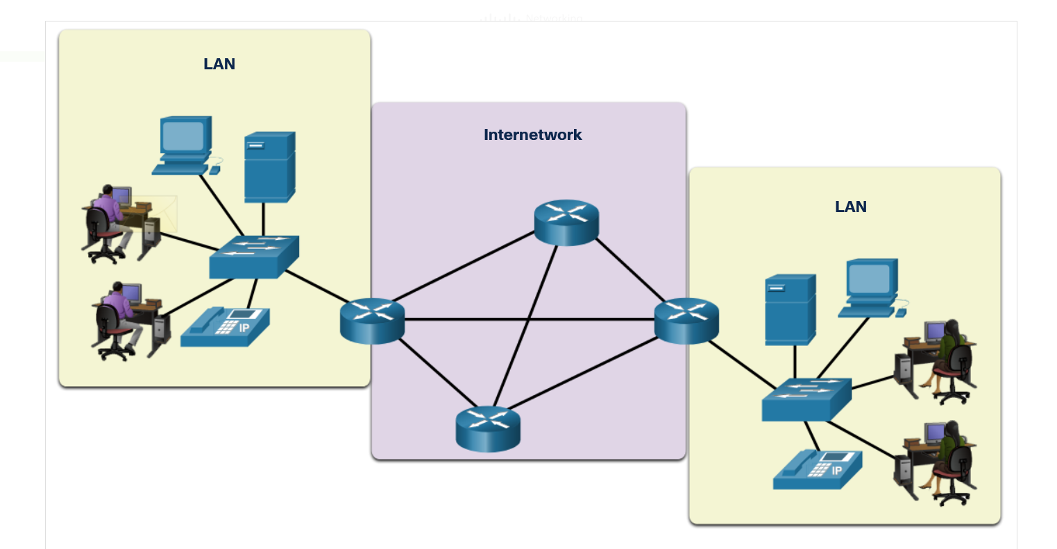
12 |
13 | - **Messages can take alternate routes.**
14 |
15 | 
16 |
17 | 
18 |
19 | 
20 |
21 | 
22 |
--------------------------------------------------------------------------------
/03. Network Protocols and Architecture/3. Routing Between Networks/2. The Routing Table/3. Routing Table Entries/README.md:
--------------------------------------------------------------------------------
1 | # Routing Table Entries
2 |
3 | - Routers move information between local and remote networks.
4 | - To do this, routers must use routing tables to store information.
5 | - Routing tables are not concerned with the addresses of individual hosts.
6 | - Routing tables contain the addresses of networks, and the best path to reach those networks.
7 | - Entries can be made to the routing table in two ways:
8 |
9 | - dynamically updated by information received from other routers in the network,
10 | - or manually entered by a network administrator
11 |
12 | - Routers use the routing tables to determine which interface to use to forward a message to its intended destination.
13 | - If the router cannot determine where to forward a message, it will drop it.
14 | - Network administrators configure a static default route that is placed into the routing table so that a packet will not be dropped due to the destination network not being in the routing table.
15 | - A default route is the interface through which the router forwards a packet containing an unknown destination IP network address.
16 | - This default route usually connects to another router that can forward the packet towards its final destination network.
17 |
--------------------------------------------------------------------------------
/04. Data Communications and Network Services/3. Transport Layer Services/1. Client - Server Relationship/3. URI, URN, URL/README.md:
--------------------------------------------------------------------------------
1 | # URI, URL and URN
2 |
3 | ## 1. URI
4 |
5 | - Web resources and web services such as RESTful APIs are identified using a Uniform Resource Identifier (URI).
6 | - A URI is a string of characters that identifies a specific network resource. As shown in the figure, a URI has two specializations:
7 |
8 | ## 2. URN:
9 |
10 | - Uniform Resource Name.
11 | - This identifies only the namespace of the resource (web page, document, image, etc.) without reference to the protocol.
12 |
13 | ## 3. URL:
14 |
15 | - This defines the network location of a specific resource on the network.
16 | - HTTP or HTTPS URLs are typically used with web browsers.
17 | - Other protocols such as FTP, SFTP, SSH, and others can use a URL.
18 | - A URL using SFTP might look like: sftp://sftp.example.com.
19 |
20 | ## These are the parts of a URI, as shown in the figure:
21 |
22 | Protocol/scheme - HTTPS or other protocols such as FTP, SFTP, mailto, and NNTP
23 | Hostname - www.example.com
24 | Path and file name - /author/book.html
25 | Fragment - #page155
26 |
27 | ## Parts of URI
28 |
29 | 
30 |
--------------------------------------------------------------------------------
/04. Data Communications and Network Services/2. IPv4 and IPv6 Address Management/2. Network Address Translation/1. NAT Operation/README.md:
--------------------------------------------------------------------------------
1 | # NAT Opeartion
2 |
3 | - The wireless router receives a public address from the ISP, which allows it to send and receive packets on the internet.
4 | - It, in turn, provides private addresses to local network clients.
5 | - Because private addresses are not allowed on the internet, a process is needed for translating private addresses into unique public addresses to allow local clients to communicate on the internet.
6 | - The process used to convert private addresses to internet-routable addresses is called Network Address Translation (NAT).
7 | - With NAT, a private (local) source IPv4 address is translated to a public (global) address.
8 | - The process is reversed for incoming packets.
9 | - The wireless router is able to translate many internal IPv4 addresses to the same public address, by using NAT.
10 | - Only packets destined for other networks need to be translated.
11 | - These packets must pass through the gateway, where the wireless router replaces the private IPv4 address of the source host with its own public IPv4 address.
12 | - Although each host on the internal network has a unique private IPv4 address assigned to it, the hosts must share the single internet-routable address assigned to the wireless router.
13 |
--------------------------------------------------------------------------------
/06. Connecting to Internet/1. ISP Connectivity Options/2. ISP Connections/README.md:
--------------------------------------------------------------------------------
1 | # ISP Connections
2 |
3 | - The interconnection of ISPs that forms the backbone of the internet is a complex web of fiber-optic cables with expensive networking switches and routers that direct the flow of information between source and destination hosts.
4 | - Average home users are not aware of the infrastructure outside of their network.
5 | - For a home user, connecting to the ISP is a fairly uncomplicated process.
6 |
7 | - The top portion of the figure displays the simplest ISP connection option.
8 | - It consists of a modem that provides a direct connection between a computer and the ISP.
9 | - This option should not be used though, because your computer is not protected on the internet.
10 |
11 | - As shown in the bottom portion of the figure, a router is required to securely connect a computer to an ISP.
12 | - This is the most common connection option.
13 | - It consists of using a wireless integrated router to connect to the ISP.
14 | - The router includes a switch to connect wired hosts and a wireless AP to connect wireless hosts.
15 | - The router also provides client IP addressing information and security for inside hosts.
16 |
17 | 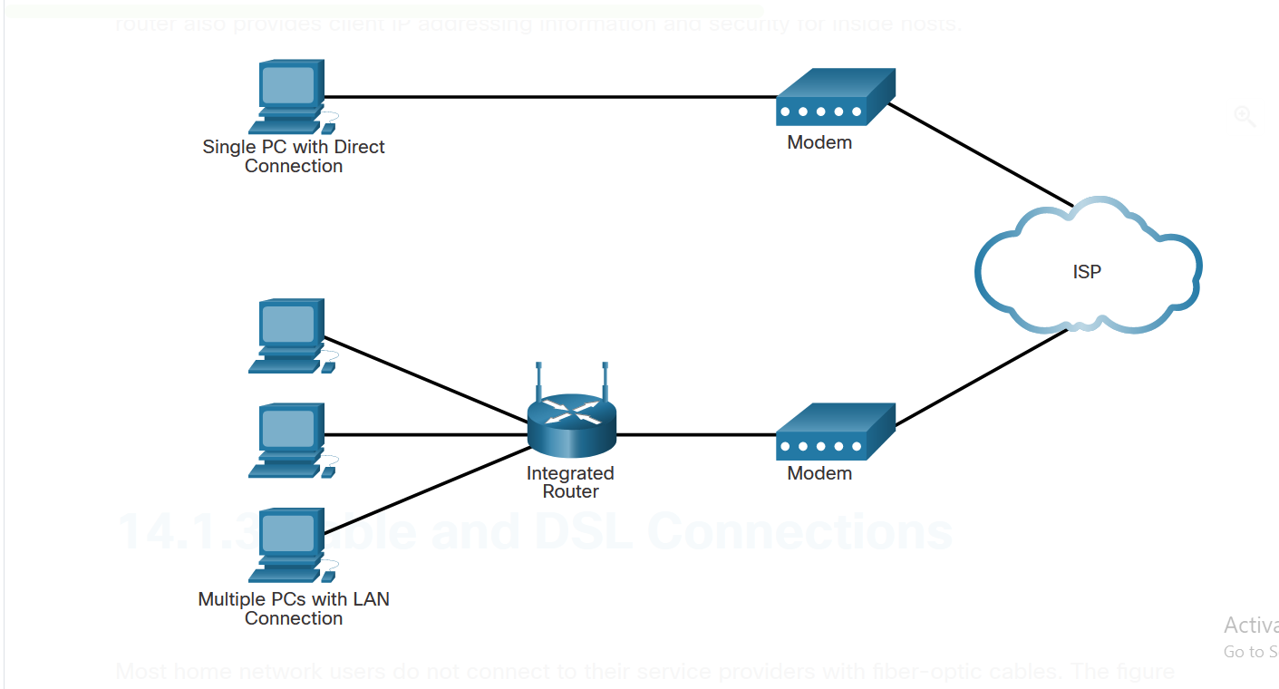
18 |
19 |
--------------------------------------------------------------------------------
/04. Data Communications and Network Services/1. Dynamic Addressing with DHCP/2. DHCPv4 Configuration/1. DHCPv4 Operation/README.md:
--------------------------------------------------------------------------------
1 | # DHCPv4 Operation
2 |
3 | - When a host is first configured as a DHCP client, it does not have an IPv4 address, subnet mask, or default gateway.
4 | - It obtains this information from a DHCP server, either on the local network or one located at the ISP.
5 | - The DHCP server is configured with a range, or pool, of IPv4 addresses that can be assigned to DHCP clients.
6 | - The DHCP server may be located on another network.
7 | - DHCP clients are still able to obtain IPv4 addresses as long as the routers in-between are configured to forward DHCP requests.
8 | - A client that needs an IPv4 address will send a DHCP Discover message which is a broadcast with a destination IPv4 address of 255.255.255.255 (32 ones) and a destination MAC address of FF-FF-FF-FF-FF-FF (48 ones).
9 | - All hosts on the network will receive this broadcast DHCP frame, but only a DHCP server will reply. The server will respond with a DHCP Offer, suggesting an IPv4 address for the client.
10 | - The host then sends a DHCP Request asking to use the suggested IPv4 address.
11 | - The server responds with a DHCP Acknowledgment, as shown in the figure.
12 |
13 | 
14 |
--------------------------------------------------------------------------------
/01. Internet Connection/3. Bandwidth & Throughput/2. Throughput/README.md:
--------------------------------------------------------------------------------
1 | # Throughput
2 |
3 | - Like bandwidth, throughput is the measure of the transfer of bits across the media over a given period of time.
4 | - However, due to a number of factors, throughput does not usually match the specified bandwidth.
5 | - Many factors influence throughput including:
6 |
7 | - The amount of data being sent and received over the connection
8 | - The types of data being transmitted
9 | - The latency created by the number of network devices encountered between source and destination
10 |
11 | - Throughput measurements do not take into account the validity or usefulness of the bits being transmitted and received.
12 | - Many messages received through the network are not destined for specific user applications.
13 | - An example would be network control messages that regulate traffic and correct errors.
14 | - In an internetwork or network with multiple segments, throughput cannot be faster than the slowest link of the path from sending device to the receiving device.
15 | - Even if all or most of the segments have high bandwidth, it will only take one segment in the path with lower bandwidth to create a slowdown of the throughput of the entire network.
16 |
17 | ## Latency
18 |
19 | - Latency refers to the amount of time, including delays, for data to travel from one given point to another.
20 |
--------------------------------------------------------------------------------
/03. Network Protocols and Architecture/4. The Internet Protocol/6. Unicast, Broadcast and Multicast Addresses/2. Broadcast Transmission/README.md:
--------------------------------------------------------------------------------
1 | # Broadcast Transmission
2 |
3 | - Broadcast packets are sent to all hosts in the network using a broadcast address. With a broadcast, the packet contains a destination IPv4 address with all ones (1s) in the host portion.
4 | - This means that all hosts on that local network (broadcast domain) will receive and look at the packet.
5 | - Many network protocols, such as DHCP, use broadcasts.
6 | - When a host receives a packet sent to the network broadcast address, the host processes the packet as it would a packet addressed to its unicast address.
7 | - Broadcast may be directed or limited.
8 | - A directed broadcast is sent to all hosts on a specific network.
9 | - For example, a host on the 172.16.4.0/24 network sends a packet to 172.16.4.255.
10 | - A limited broadcast is sent to 255.255.255.255. By default, routers do not forward broadcasts.
11 | - When a packet is broadcast, it uses resources on the network and causes every receiving host on the network to process the packet.
12 | - Therefore, broadcast traffic should be limited so that it does not adversely affect the performance of the network or devices.
13 | - Because routers separate broadcast domains, subdividing networks can improve network performance by eliminating excessive broadcast traffic.
14 |
--------------------------------------------------------------------------------
/07. Network and Device Security/4. DoS Attacks/1. Denial of Service/README.md:
--------------------------------------------------------------------------------
1 | # Denial of Service (DoS)
2 |
3 | - DoS attacks are aggressive attacks on an individual computer or groups of computers with the intent to deny services to intended users.
4 |
5 | - DoS attacks can target end user systems, servers, routers, and network links. DoS attacks are relatively simple and can be initiated by an unskilled threat actor.
6 |
7 | A threat actor uses a DoS attack to perform these functions:
8 |
9 | 1. Flood a network, host, or application with traffic to prevent legitimate network traffic from flowing.
10 | 2. Disrupt connections between a client and server to prevent access to a service.
11 |
12 | - There are several types of DoS attacks. Security administrators need to be aware of the types of DoS attacks that can occur and ensure that their networks are protected.
13 |
14 | These are two common DoS attacks:
15 |
16 | 1. SYN (synchronous) flooding - This is when a flood of packets are sent to a server requesting a client connection. The packets contain invalid source IP addresses. The server becomes occupied trying to respond to these fake requests and therefore cannot respond to legitimate ones.
17 | 2. Ping of death - This is when a packet that is greater in size than the maximum allowed by IP (65,535 bytes) is sent to a device. This can cause the receiving system to crash.
18 |
--------------------------------------------------------------------------------
/07. Network and Device Security/3. Malware/3. Spyware/README.md:
--------------------------------------------------------------------------------
1 | # Spyware
2 |
3 | - Not all attacks do damage or prevent legitimate users from having access to resources.
4 | - Many threats are designed to collect information about users which can be used for advertising, marketing, and research purposes.
5 | - These include spyware, tracking cookies, adware, and popups.
6 | - While these may not damage a computer, they invade privacy and can be annoying.
7 |
8 | - **Spyware** is any program that gathers personal information from your computer without your permission or knowledge.
9 | - This information is sent to advertisers or others on the internet and can include passwords and account numbers.
10 |
11 | - Spyware is usually installed unknowingly when downloading a file, installing another program, or clicking a popup.
12 | - It can slow down a computer and make changes to internal settings which creates more vulnerabilities for other threats.
13 | - In addition, spyware can be very difficult to remove.
14 |
15 | ## Tracking Cookies
16 |
17 | - Cookies are a form of spyware but are not always bad.
18 | - They are used to record information about an internet user when the user visits websites.
19 | - Cookies may be useful or desirable by allowing personalization and other time saving techniques.
20 |
21 | - Many websites require that cookies be enabled in order to allow the user to connect.
22 |
--------------------------------------------------------------------------------
/03. Network Protocols and Architecture/2. Network Design & the Access Layer/2. Hierarchical Network Design/1. Physical & Logical Addresses/README.md:
--------------------------------------------------------------------------------
1 | # Physical & Logical Addresses
2 |
3 | - On a host, the MAC address does not change; it is physically assigned to the host NIC and is known as the physical address.
4 | - The physical address remains the same regardless of where the host is placed on the network.
5 | - The IP address is similar to the address of a person. It is known as a logical address because it is assigned logically based on where the host is located.
6 | - The IP address, or network address, is assigned to each host by a network administrator based on the local network.
7 | - IP addresses contain two parts. One part identifies the network portion.
8 | - The network portion of the IP address will be the same for all hosts connected to the same local network.
9 | - The second part of the IP address identifies the individual host on that network.
10 | - Within the same local network, the host portion of the IP address is unique to each host, as shown in the figure.
11 | - Both the physical MAC and logical IP addresses are required for a computer to communicate on a hierarchical network, just like both the name and address of a person are required to send a letter.
12 |
13 | 
14 |
--------------------------------------------------------------------------------
/03. Network Protocols and Architecture/2. Network Design & the Access Layer/3. The Access Layer & Devices/2. Ethernet Switches/README.md:
--------------------------------------------------------------------------------
1 | # Ethernet Switches
2 |
3 | - An Ethernet switch is a device that is used at the access layer.
4 | - When a host sends a message to another host connected to the same switched network, the switch accepts and decodes the frames to read the physical (MAC) address portion of the message.
5 | - A table on the switch, called a MAC address table, contains a list of all of the active ports and the host MAC addresses that are attached to them.
6 | - When a message is sent between hosts, the switch checks to see if the destination MAC address is in the table.
7 | - If it is, the switch builds a temporary connection, called a circuit, between the source and destination ports.
8 | - This new circuit provides a dedicated channel over which the two hosts can communicate.
9 | - Other hosts attached to the switch do not share bandwidth on this channel and do not receive messages that are not addressed to them.
10 | - A new circuit is built for every new conversation between hosts.
11 | - These separate circuits allow many conversations to take place at the same time, without collisions occurring.
12 | - Ethernet switches also allow for the sending and receiving of frames over the same Ethernet cable simultaneously.
13 | - This improves the performance of the network by eliminating collisions.
14 |
--------------------------------------------------------------------------------
/08. Security Configuration/1. Wireless Security Measures/3. SSID Broadcasts/README.md:
--------------------------------------------------------------------------------
1 | # SSID Broadcast
2 |
3 | - One easy way to gain entry to a wireless network is through the network name, or SSID.
4 |
5 | - All computers connecting to the wireless network must be configured with or connect to the appropriate SSID.
6 | - By default, wireless routers and access points broadcast SSIDs to all computers within the wireless range.
7 | - With SSID broadcast activated, any wireless client can detect the network and connect to it, if no other security features are in place.
8 |
9 | - The SSID broadcast feature can be turned off.
10 | - When it is turned off, the fact that the network is there is no longer made public.
11 | - Any computer trying to connect to the network must already know the SSID.
12 | - Turning off SSID broadcast alone does not protect the wireless network from experienced threat actors.
13 | - The SSID can be determined by capturing and analyzing the wireless packets that are exchanged between the clients and the access point.
14 | - Even with SSID broadcasting disabled, it is possible for someone to get into your network using the well-known default SSID.
15 | - Additionally, if other default settings, such as passwords and IP addresses are not changed, attackers can access an AP and make changes themselves.
16 | - Default information should be changed to something more secure and unique.
17 |
--------------------------------------------------------------------------------
/08. Security Configuration/3. Configure a Firewall/3. The DMZ/README.md:
--------------------------------------------------------------------------------
1 | # The DMZ
2 |
3 | - Many home network devices, such as wireless routers, frequently include multifunction firewall software.
4 | - This firewall typically provides NAT in addition to IP, application, and website filtering capabilities.
5 |
6 | - They also support demilitarized zone (DMZ) capabilities, as shown in the figure.
7 |
8 | 
9 |
10 |
11 | - In computer networking, a demilitarized zone (DMZ) refers to an area of the network that is accessible and controlled for both internal and external users.
12 | - It is more secure than the external network but not as secure as the internal network.
13 |
14 | - With the wireless router, a simple DMZ can be set up that allows an internal server to be accessible by outside hosts.
15 | - To accomplish this, the server requires a static IP address that must be specified in the DMZ configuration.
16 | - The wireless router isolates traffic destined to the IP address specified.
17 | - This traffic is then forwarded only to the switch port where the server is connected.
18 | - All other hosts are still protected by the firewall.
19 | - Game servers and other devices that need to be accessed directly by users located on the internet may need to be configured in the DMZ network.
20 |
--------------------------------------------------------------------------------
/08. Security Configuration/3. Configure a Firewall/5. Port Triggering/README.md:
--------------------------------------------------------------------------------
1 | # Port Triggering
2 |
3 | - Playing a game over the internet may require more than just a data connection between you and the other players.
4 | - You may want to talk with your friends, or chat, while playing.
5 | - In many multiplayer games, a number of TCP and UDP connections could exist between the players while the game is active.
6 |
7 | - Leaving a large number of ports open to the internet can represent a security risk.
8 |
9 | - Port triggering allows the router to temporarily forward data through inbound TCP or UDP ports to a specific device.
10 | - You can use port triggering to forward data to a computer only when a designated port range is used to make an outbound request.
11 | - For example, a video game might use ports 27000 to 27100 for connecting with other players.
12 | - These are the trigger ports.
13 | - A chat client might use port 56 for connecting the same players so that they can communicate with each other while playing the game.
14 | - In this instance, if there is gaming traffic on an outbound port within the triggered port range, inbound chat traffic on port 56 is forwarded to the computer that is being used to play the video game and chat with friends.
15 | - When the game is over and the triggered ports are no longer in use, port 56 is no longer allowed to send traffic of any type to this computer.
16 |
--------------------------------------------------------------------------------
/04. Data Communications and Network Services/4. Application Layer Services/6. Email and Messaging/3. Text Messaging/README.md:
--------------------------------------------------------------------------------
1 | # Text Messaging
2 |
3 | - Text messaging, shown in the figure, is one of the most popular communication tools in use today.
4 | - In addition, text messaging software is built into many online applications, smart phone apps, and social media sites.
5 |
6 | 
7 |
8 | - Both clients can simultaneously send and receive messages.
9 |
10 | - Text messages may also be called instant messages, direct messages, private messages, and chat messages.
11 | - Text messaging enables users to communicate or chat over the internet in real-time.
12 | - Text messaging services on a computer are usually accessed through a web-based client that is integrated into a social media or information sharing site.
13 | - These clients usually only connect to other users of the same site.
14 |
15 | - There are also a number of standalone text message clients such as Cisco Webex Teams, Microsoft Teams, WhatsApp, Facebook Messenger, and many others.
16 | - These applications are available for a wide variety of operating systems and devices.
17 | - A mobile version is typically offered. In addition to text messages, these clients support the transfer of documents, video, music, and audio files.
18 |
19 |
--------------------------------------------------------------------------------
/04. Data Communications and Network Services/1. Dynamic Addressing with DHCP/1. Static and Dynamic Addressing/2. Dynamic Addressing/README.md:
--------------------------------------------------------------------------------
1 | # Dynamic IPv4 Address Assignment
2 |
3 | - On local networks it is often the case that the user population changes frequently.
4 | - New users arrive with laptops and need a connection.
5 | - Others have new workstations that need to be connected.
6 | - Rather than have the network administrator assign IPv4 addresses for each workstation, it is easier to have IPv4 addresses assigned automatically.
7 | - This is done using a protocol known as Dynamic Host Configuration Protocol (DHCP).
8 | - DHCP automatically assigns addressing information such as IPv4 address, subnet mask, default gateway, and other configuration information, as shown in the figure.
9 | - DHCP is generally the preferred method of assigning IPv4 addresses to hosts on large networks because it reduces the burden on network support staff and virtually eliminates entry errors.
10 | - Another benefit of DHCP is that an address is not permanently assigned to a host but is only leased for a period of time.
11 | - If the host is powered down or taken off the network, the address is returned to the pool for reuse.
12 | - This is especially helpful with mobile users that come and go on a network.
13 |
14 | 
15 |
--------------------------------------------------------------------------------
/07. Network and Device Security/1. Security Threats/2. Internal and External Threats/README.md:
--------------------------------------------------------------------------------
1 | ## External Threats
2 |
3 | - External threats arise from individuals working outside of an organization.
4 | - They do not have authorized access to the computer systems or network.
5 |
6 | - External attackers work their way into a network mainly from the internet through wireless links or dialup access servers.
7 |
8 |
9 | ## Internal Threats
10 |
11 | - Internal threats occur when someone has authorized access to the network through a user account, or has physical access to the network equipment.
12 | - Internal attackers know the internal politics and people.
13 | - They often know what information is both valuable and vulnerable, and how to get to it.
14 |
15 | - However, not all internal attacks are intentional.
16 | - In some cases, an internal threat can come from a trustworthy employee who picks up a virus or security threat while outside the company and unknowingly brings it into the internal network.
17 |
18 | - Most companies spend considerable resources defending against external attacks, however; some of the most damaging incidents are the result of actions by trusted internal users.
19 | - Lost smart phones and removable storage devices, misplaced or stolen laptops, and the failure to properly remove data from devices before disposal are common ways that user data ends up in the hands of the wrong people.
20 |
--------------------------------------------------------------------------------
/09. Intro to Cisco Networking/1. Cisco Switches/4. In-band & Out-of-Band Management/README.md:
--------------------------------------------------------------------------------
1 | **There are two methods to connect a PC to a network device to perform configuration and monitoring tasks:**
2 |
3 | ## 1. Out-of-band Management
4 |
5 | - `Out-of-band management` requires a computer to be directly connected to the console port of the network device that is being configured.
6 | - This type of connection does not require the local network connections on the device to be active.
7 | - Technicians use out-of-band management to initially configure a network device, because until properly configured, the device cannot participate in the network.
8 |
9 | - Out-of-band management is also useful when the network connectivity is not functioning correctly, and the device cannot be reached over the network.
10 | - Performing out-of-band management tasks requires a terminal emulation client installed on the PC.
11 |
12 | ## 2. In-band Managemnt
13 |
14 | - Use `in-band management` to monitor and make configuration changes to a network device over a network connection.
15 | - For a computer to connect to the device and perform in-band management tasks, at least one network interface on the device must be connected to the network and have an IP address configured on it.
16 |
17 | - Either Telnet, HTTP or SSH can be used to access a Cisco device for in-band management, monitor the network device, or make configuration changes.
18 |
--------------------------------------------------------------------------------
/07. Network and Device Security/5. Antimalware Software/5. Additional Safeguards/README.md:
--------------------------------------------------------------------------------
1 | # Additional Safeguards
2 |
3 | - One of the most common types of spam forwarded is a virus warning.
4 |
5 | - Although some virus warnings sent via email are true, a large number of them are hoaxes and do not really exist.
6 | - This type of spam can create problems because people warn others of the impending disaster and so flood the email system.
7 | - In addition, network administrators may overreact and waste time investigating a problem that does not exist.
8 | - Finally, many of these emails can actually contribute to the spread of viruses, worms, and Trojan horses.
9 |
10 | - In addition to using spam blockers, other actions to prevent the spread of spam include the following:
11 |
12 | 1. Apply OS and application updates when available.
13 | 2. Run an antivirus program regularly and keep it up to date.
14 | 3. Do not forward suspicious emails.
15 | 4. Do not open email attachments, especially from people you do not know.
16 | 5. Set up rules in your email to delete spam that bypass the antispam software.
17 | 6. Identify sources of spam and report it to a network administrator so it can be blocked.
18 |
19 | 7. Report incidents to the governmental agency that deals with abuse by spam.
20 |
21 | 
22 |
--------------------------------------------------------------------------------
/04. Data Communications and Network Services/4. Application Layer Services/6. Email and Messaging/2. Email Protocols/README.md:
--------------------------------------------------------------------------------
1 | # Email Protocols
2 |
3 | ## SMTP
4 |
5 | - Simple Mail Transfer Protocol
6 | - SMTP is used by an email client to send messages to its local email server.
7 | - The local server then decides if the message is destined for a local mailbox or if the message is addressed to a mailbox on another server.
8 |
9 | - If the server has to send the message to a different server, SMTP is used between those two servers as well. SMTP requests are sent to port 25.
10 |
11 | ## POP3
12 |
13 | - Post Office Protocol 3
14 |
15 | - A server that supports POP clients receives and stores messages addressed to its users.
16 | - When the client connects to the email server, the messages are downloaded to the client.
17 | - By default, messages are not kept on the server after they have been accessed by the client.
18 | - Clients contact POP3 servers on port 110.
19 |
20 | ## IMAP4
21 |
22 | - Internet Message Access Protocol 4
23 | - A server that supports IMAP clients also receives and stores messages addressed to its users.
24 | - However, unlike POP, IMAP keeps the messages in the mailboxes on the server, unless they are deleted by the user.
25 | - The most current version of IMAP is IMAP4 which listens for client requests on port 143.
26 |
27 | - Many different email servers exist for the various network operating system platforms.
28 |
--------------------------------------------------------------------------------
/04. Data Communications and Network Services/1. Dynamic Addressing with DHCP/1. Static and Dynamic Addressing/1. Static Addressing/README.md:
--------------------------------------------------------------------------------
1 | # Static IPv4 Address Assignment
2 |
3 | - IPv4 addresses can be assigned either statically or dynamically.
4 | - With a static assignment, the network administrator must manually configure the network information for a host.
5 | - At a minimum, this includes the host IPv4 address, subnet mask, and default gateway, as shown in the figure.
6 | - Static addresses have some advantages.
7 | - For instance, they are useful for printers, servers, and other networking devices that need to be accessible to clients on the network.
8 | - If hosts normally access a server at a particular IPv4 address, it would not be good if that address changed.
9 | - Static assignment of addressing information can provide increased control of network resources, but it can be time consuming to enter the information on each host.
10 | - When IPv4 addresses are entered statically, the host only performs basic error checks on the IPv4 address.
11 | - Therefore, errors are more likely to occur.
12 | - When using static IPv4 addressing, it is important to maintain an accurate list of which IPv4 addresses are assigned to which devices.
13 | - Additionally, these are permanent addresses and are not normally reused.
14 |
15 | 
16 |
17 |
--------------------------------------------------------------------------------
/07. Network and Device Security/5. Antimalware Software/1. Signs of Infection/README.md:
--------------------------------------------------------------------------------
1 | # Signs of Infection
2 |
3 | - Even when the OS and applications have all the current patches and updates, they may still be susceptible to attack.
4 | - Any device that is connected to a network is susceptible to viruses, worms, and Trojan horses.
5 | - These may be used to corrupt OS code, affect computer performance, alter applications, and destroy data.
6 | - So how do you know if your computer has been infected?
7 |
8 | - Some of the signs that a virus, worm, or Trojan horse may be present include the following:
9 |
10 | 1. Computer starts acting abnormally
11 | 2. Program does not respond to mouse and keystrokes
12 | 3. Programs starting or shutting down on their own
13 | 4. Email program begins sending out large quantities of email
14 | 5. CPU usage is very high
15 | 6. There are unidentifiable processes or a large number of processes running
16 | 7. Computer slows down significantly or crashes, such as the when the Windows “blue screen of death” (BSoD) appears, as shown in the figure.
17 |
18 | - Antimalware includes a variety of software available to detect and prevent these types of intrusions and infections including antivirus software, antispam software, and antispyware software.
19 |
20 | ### Windows BSoD
21 |
22 | 
23 |
--------------------------------------------------------------------------------
/04. Data Communications and Network Services/3. Transport Layer Services/1. Client - Server Relationship/2. Client Requests a Webpage/README.md:
--------------------------------------------------------------------------------
1 | # Client Requests a Web Page
2 |
3 | - Much of the information that we receive over the internet is provided in the form of web page documents.
4 | - To request and view a web page, a person uses a device that is running web client software, such as a web browser.
5 | - The key characteristic of client/server systems is that the client sends a request to a server, and the server responds by carrying out a function, such as sending the requested document back to the client.
6 | - The combination of a web browser and a web server is perhaps the most commonly used instance of a client/server system.
7 | - A web server is usually in a part of the network with other servers called a server farm, or within a data center.
8 | - A data center is a facility used to house computer systems and associated components.
9 | - A data center can occupy one room of a building, one or more floors, or an entire building.
10 | - Data centers are typically very expensive to build and maintain.
11 | - For this reason, only large organizations use privately built data centers to house their data and provide services to users.
12 | - Smaller organizations that cannot afford to maintain their own private data center can reduce the overall cost of ownership by leasing server and storage services from a larger data center organization in the cloud.
13 |
14 |
--------------------------------------------------------------------------------
/04. Data Communications and Network Services/4. Application Layer Services/6. Email and Messaging/4. Internet Phonecalls/README.md:
--------------------------------------------------------------------------------
1 | # Internet Phonecalls
2 |
3 | - Making telephone calls over the internet is becoming increasingly popular.
4 | - An internet telephony client uses peer-to-peer technology similar to that used by instant messaging, as shown in the figure.
5 | - IP telephony makes use of Voice over IP (VoIP) technology, which converts analog voice signals into digital data.
6 | - The voice data is encapsulated into IP packets which carry the phone call through the network.
7 |
8 | - When the IP phone software has been installed, the user selects a unique name.
9 | - This is so that calls can be received from other users.
10 | - Speakers and a microphone, built-in or separate, are required.
11 | - A headset is frequently plugged into the computer to serve as a phone.
12 |
13 | - Calls are made to other users of the same service on the internet, by selecting the username from a list.
14 | - A call to a regular telephone (landline or cell phone) requires using a gateway to access the Public Switched Telephone Network (PSTN).
15 | - Depending on the service, there may be charges associated with this type of call.
16 | - The protocols and destination ports used by internet telephony applications can vary based on the software.
17 |
18 | 
19 |
20 |
--------------------------------------------------------------------------------
/04. Data Communications and Network Services/3. Transport Layer Services/1. Client - Server Relationship/1. Client and Server Interaction/README.md:
--------------------------------------------------------------------------------
1 | # Client - Server Interaction
2 |
3 | - The term server refers to a host running a software application that provides information or services to other hosts that are connected to the network.
4 | - A well-known example of an application is a web server.
5 | - There are millions of servers connected to the internet, providing services such as web sites, email, financial transactions, music downloads, etc.
6 | - A crucial factor to enable these complex interactions to function is that they all use agreed upon standards and protocols.
7 | - An example of client software is a web browser, like Chrome or Firefox.
8 | - A single computer can also run multiple types of client software.
9 | - For example, a user can check email and view a web page while instant messaging and listening to an audio stream.
10 |
11 | | **Type** | **Description** |
12 | | --- | --- |
13 | | Email | The email server runs the email server software. Clients use mail client software, such as Microsoft Outlook, to access email on the server |
14 | | Web | The Web server runs the web server software. Clients use browser software, such as Windows Internet Explorer, to access web pages on the server |
15 | | File | The file server stores corporate and user files in a central location. The client devices access these files with client software such as the Windows File Explorer |
16 |
17 |
--------------------------------------------------------------------------------
/01. Internet Connection/1. Communications in a Connected World/4. Other Devices/README.md:
--------------------------------------------------------------------------------
1 | # Other Devices
2 |
3 | ## 1. Smart Cars
4 |
5 | - Many modern cars can connect to the Internet to access maps, audio and video content, or information about a destination. They can even send a text message or email if there is an attempted theft or call for assistance in case of an accident. These cars can also connect to smart phones and tablets to display information about the different engine systems, provide maintenance alerts, or display the status of the security system.
6 |
7 | ## 2. RFID
8 |
9 | - Radio frequency identification (RFIDs) tags can be placed in or on objects to track them or monitor sensors for many conditions.
10 |
11 | ## 3. Sensors and Actuators
12 |
13 | - Connected sensors can provide temperature, humidity, wind speed, barometric pressure, and soil moisture data.
14 | - Actuators can then be automatically triggered based on current conditions.
15 | - For example, a smart sensor can periodically send soil moisture data to a monitoring station.
16 | - The monitoring station can then send a signal to an actuator to begin watering.
17 | - The sensor will continue to send soil moisture data allowing the monitoring station to determine when to deactivate the actuator.
18 |
19 | ## 4. Medical Devices
20 |
21 | - Medical devices such as pacemakers, insulin pumps, and hospital monitors provide users or medical professionals with direct feedback or alerts when vital signs are at specific levels.
22 |
--------------------------------------------------------------------------------
/04. Data Communications and Network Services/4. Application Layer Services/1. Network Application Services/1. Common Network Application Services/README.md:
--------------------------------------------------------------------------------
1 | # Common Network Application Services
2 |
3 | - Some of the most common servers that provide us the services are shown in the figure.
4 |
5 | 
6 |
7 | - A brief description of each service is shown in the table.
8 |
9 | | Protocol | Description |
10 | | --- | --- |
11 | | Domain Name System (DNS) | Resolves internet names to IP addresses |
12 | | Secure Shell (SSH) | Used to provide remote access to servers and networking devices |
13 | | Simple Mail Transfer Protocol (SMTP) | Sends email messages and attachments from client to servers and vice versa |
14 | | Post Office Protocol (POP3) | Used by email clients to retrieve email and attachments from remote server |
15 | | Internet Message Access Protocol (IMAP) | Used by email clients to retrieve email and attachments from remote server |
16 | | Dynamic Host Configuration Protocol (DHCP) | Used to automatically configure devices with IP addressing and other necessary information to enable them to communicate over the internet |
17 | | Hypertext Transfer Protocol (HTTP) | Used by browsers to request web pages and web servers to transfersthe files that make up web pages of the World Wide Web |
18 | | File Transfer Protocol (FTP) | Used for interactive file transfer between systems |
19 |
--------------------------------------------------------------------------------
/03. Network Protocols and Architecture/4. The Internet Protocol/6. Unicast, Broadcast and Multicast Addresses/3. Multicast Transmission/README.md:
--------------------------------------------------------------------------------
1 | # Multicast Transmission
2 |
3 | - Multicast transmission reduces traffic by allowing a host to send a single packet to a selected set of hosts that subscribe to a multicast group.
4 | - IPv4 has reserved the 224.0.0.0 to 239.255.255.255 addresses as a multicast range.
5 | - The IPv4 multicast addresses 224.0.0.0 to 224.0.0.255 are reserved for multicasting on the local network only.
6 | - These addresses are to be used for multicast groups on a local network.
7 | - A router connected to the local network recognizes that these packets are addressed to a local network multicast group and never forwards them further.
8 | - A typical use of reserved local network multicast address is in routing protocols using multicast transmission to exchange routing information.
9 | - For instance, 224.0.0.9 is the multicast address used by Routing Information Protocol (RIP) version 2 to communicate with other RIPv2 routers.
10 | - Hosts that receive particular multicast data are called multicast clients.
11 | - The multicast clients use services requested by a client program to subscribe to the multicast group.
12 | - Each multicast group is represented by a single IPv4 multicast destination address.
13 | - When an IPv4 host subscribes to a multicast group, the host processes packets addressed to this multicast address, and packets addressed to its uniquely allocated unicast address.
14 |
--------------------------------------------------------------------------------
/04. Data Communications and Network Services/4. Application Layer Services/5. Virtual Terminals/2. Security Issues with TelNet/README.md:
--------------------------------------------------------------------------------
1 | # Security issues with the Telnet
2 |
3 | - After a Telnet connection is established, users can perform any authorized function on the server, just as if they were using a command line session on the server itself.
4 | - If authorized, they can start and stop processes, configure the device, and even shut down the system.
5 | - Although the Telnet protocol can require a user to login, it does not support transporting encrypted data.
6 | - All data exchanged during Telnet sessions is transported as plaintext across the network.
7 | - This means that the data can be easily intercepted and understood.
8 | - The Secure Shell (SSH) protocol offers an alternate and secure method for server access.
9 | - SSH provides the structure for secure remote login and other secure network services.
10 | - It also provides stronger authentication than Telnet and supports transporting session data using encryption.
11 | - As a best practice, network professionals should always use SSH in place of Telnet, whenever possible.
12 | - The figure illustrates how SSH is more secure than Telnet.
13 |
14 | - Notice how the data captured by the hacker when Telnet is used is clearly readable while the data captured when SSH is used is encrypted and therefore more secure.
15 |
16 | 
17 |
--------------------------------------------------------------------------------
/03. Network Protocols and Architecture/3. Routing Between Networks/2. The Routing Table/1. Path Selection/README.md:
--------------------------------------------------------------------------------
1 | # Path Selection
2 |
3 | **How does the router determine which interface to use to send the message on a path to get to the destination network?**
4 |
5 | - Each port, or interface, on a router connects to a different local network.
6 | - Every router contains a table of all locally connected networks and the interfaces that connect to them.
7 | - These routing tables can also contain information about the routes, or paths, that the router uses to reach other remote networks that are not locally attached.
8 | - When a router receives a frame, it decodes the frame to get to the packet containing the destination IP address.
9 | - It matches the network portion of the destination IP address to the networks that are listed in the routing table.
10 | - If the destination network address is in the table, the router encapsulates the packet in a new frame in order to send it out.
11 |
12 | (Note that it will insert a new destination MAC address as well, and recalculate the FCS field, in the new frame).
13 |
14 | - It forwards the new frame out of the interface associated with the path, to the destination network.
15 | - The process of forwarding the packets toward their destination network is called routing.
16 | - Router interfaces do not forward messages that are addressed to the local network broadcast IP address.
17 | - As a result, local network broadcasts are not sent across routers to other local networks.
18 |
--------------------------------------------------------------------------------
/08. Security Configuration/3. Configure a Firewall/2. Firewall Operation/README.md:
--------------------------------------------------------------------------------
1 | # Firewall Operation
2 |
3 | - Firewalls can be implemented in software which is to be loaded onto PCs, networking devices, or servers.
4 | - Firewalls may also be hardware devices that are installed for the single purpose of protecting areas within the network.
5 | - A hardware firewall is a freestanding unit that does not use the resources of the computers it is protecting, so there is no impact on processing performance.
6 | - The firewall can be configured to block multiple individual external devices by IP address, to permit or deny packets matching the range of TCP or UDP ports that you specify, or even traffic that is specific to an application such as a multiplayer video game.
7 |
8 | - Typically a hardware firewall passes two different types of traffic into your network:
9 |
10 | Responses to traffic that originates from inside your network
11 | Traffic that originated from outside the organization that is destined for a port that you have intentionally permitted
12 |
13 | - Additionally, firewalls often perform Network Address Translation (NAT).
14 | - NAT translates an internal private address or group of addresses into registered IP addresses that can be sent across the internet.
15 | - This allows internal IP addresses to be concealed from outside users.
16 |
17 | ## Firewall Operation
18 |
19 | 
20 |
--------------------------------------------------------------------------------
/04. Data Communications and Network Services/4. Application Layer Services/4. FTP Clients and Server/1. File Transfer Protocol/README.md:
--------------------------------------------------------------------------------
1 | # File Transfer Protocol
2 |
3 | - In addition to web services, another common service used across the internet is one that allows users to transfer files.
4 | - The File Transfer Protocol (FTP) provides an easy method to transfer files from one computer to another.
5 | - A host running FTP client software can access an FTP server to perform various file management functions including file uploads and downloads.
6 | - The FTP server enables a client to exchange files between devices.
7 | - It also enables clients to manage files remotely by sending file management commands such as delete or rename.
8 | - To accomplish this, the FTP service uses two different ports to communicate between client and server.
9 | - The example in the figure illustrates how FTP operates.
10 | - To begin an FTP session, control connection requests are sent to the server using destination TCP port 21.
11 | - When the session is opened, the server uses TCP port 20 to transfer the data files.
12 |
13 | 
14 |
15 | - FTP client software is built into computer operating systems and into most web browsers.
16 | - Stand-alone FTP clients offer many options in an easy-to-use GUI-based interface.
17 | - Based on commands sent across the control connection, data can be downloaded from the server or uploaded from the client.
18 |
--------------------------------------------------------------------------------
/03. Network Protocols and Architecture/1. Communication Principles/4. Ethernet/2. Ethernet Evolution/README.md:
--------------------------------------------------------------------------------
1 | # Ethernet Evolution
2 |
3 | - The Institute of Electrical and Electronic Engineers, or IEEE (pronounced eye-triple-e), maintains the networking standards, including Ethernet and wireless standards.
4 |
5 | - IEEE committees are responsible for approving and maintaining the standards for connections, media requirements and communications protocols.
6 |
7 | - Each technology standard is assigned a number that refers to the committee that is responsible for approving and maintaining the standard.
8 | - The committee responsible for the Ethernet standards is 802.3.
9 |
10 | - Since the creation of Ethernet in 1973, standards have evolved for specifying faster and more flexible versions of the technology.
11 | - This ability for Ethernet to improve over time is one of the main reasons that it has become so popular.
12 | - Each version of Ethernet has an associated standard.
13 | - For example, 802.3 100BASE-T represents the 100 Megabit Ethernet using twisted-pair cable standards.
14 |
15 | **The standard notation translates as:**
16 |
17 | 100 is the speed in
18 |
19 | BASE stands for baseband transmission
20 |
21 | T stands for the type of cable, in this case, twisted-pair
22 |
23 | - Early versions of Ethernet were relatively slow at 10 Mbps.
24 | - The latest versions of Ethernet operate at 10 Gigabits per second and more.
25 | - Imagine how much faster these new versions are than the original Ethernet networks.
26 |
27 |
--------------------------------------------------------------------------------
/07. Network and Device Security/4. DoS Attacks/2. DDoS/README.md:
--------------------------------------------------------------------------------
1 | # Background
2 |
3 | - DoS attacks that are coming from a single IP address can disrupt a website for a period of time until the attack can be isolated and defended against.
4 |
5 | - More sophisticated types of attacks can bring web services offline for much longer lengths of time.
6 |
7 | ## Distributed Denial of Service (DDoS)
8 |
9 | - DDoS is a more sophisticated and potentially damaging form of the DoS attack.
10 | - It is designed to saturate and overwhelm network links with useless data.
11 | - DDoS operates on a much larger scale than DoS attacks.
12 | - Typically hundreds or thousands of attack points attempt to overwhelm a target simultaneously.
13 | - The attack points may be unsuspecting computers that have been previously infected by the DDoS code.
14 | - The systems that are infected with the DDoS code attack the target site when invoked.
15 |
16 | - This group of infected computers is often called a botnet.
17 |
18 | ## Brute Force
19 |
20 | - Not all attacks that cause network outages are specifically DoS attacks.
21 | - A brute force attack is another type of attack that may result in denial of services.
22 |
23 | - With brute force attacks, a fast computer is used to try to guess passwords or to decipher an encryption code.
24 | - The attacker tries a large number of possibilities in rapid succession to gain access or crack the code.
25 | - Brute force attacks can cause a denial of service due to excessive traffic to a specific resource, or by locking out user accounts.
26 |
--------------------------------------------------------------------------------
/03. Network Protocols and Architecture/4. The Internet Protocol/5. Public and Private IP Addresses/2. IPv4 Address Assignment/README.md:
--------------------------------------------------------------------------------
1 | # IPv4 Address Assignment
2 |
3 | - For a company or organization to support network hosts, such as web servers that are accessible from the internet, that organization must have a block of public addresses assigned.
4 | - Remember that public addresses must be unique, and use of these public addresses is regulated and allocated to each organization separately. This is true for IPv4 and IPv6 addresses.
5 | - Both IPv4 and IPv6 addresses are managed by the Internet Assigned Numbers Authority (IANA) (http://www.iana.org).
6 | - The IANA manages and allocates blocks of IP addresses to the Regional Internet Registries (RIRs).
7 | - RIRs are responsible for allocating IP addresses to ISPs who in turn provide IPv4 address blocks to organizations and smaller ISPs.
8 | - Organizations can get their addresses directly from an RIR subject to the policies of that RIR.
9 |
10 | 
11 |
12 | AfriNIC (African Network Information Centre) - Africa Region
13 | APNIC (Asia Pacific Network Information Centre) - Asia/Pacific Region
14 | ARIN (American Registry for Internet Numbers) - North America Region
15 | LACNIC (Regional Latin-American and Caribbean IP Address Registry) - Latin America and some Caribbean Islands
16 | RIPE NCC (Réseaux IP Européens Network Coordination Centre) - Europe, the Middle East, and Central Asia
17 |
18 |
--------------------------------------------------------------------------------
/01. Internet Connection/6. Online Connections/2. Local Network Connections/2. End Device Addressing/README.md:
--------------------------------------------------------------------------------
1 | # End Device Addressing
2 |
3 | - To physically connect to a network, an end-user device must have a network interface card (NIC).
4 | - The NIC is a piece of hardware that enables the device to connect to the network medium, either wired or wireless.
5 | - It may be integrated into the device motherboard or may be a separately installed card.
6 | - In addition to the physical connection, some configuration of the operating system is required for the device to participate in the network.
7 | - Most networks connect to the internet and use the internet to exchange information.
8 | - An end-user device requires an Internet Protocol (IP) address, as well as other information, to identify it to the other devices in the network.
9 |
10 |
11 | - **There are three parts to the IP configuration which must be correct for the device to send and receive information on the network:**
12 |
13 | **1. IP Address:** This identifies the host on the network.\
14 | **2. Subnet Mask:** This is used to identify the network on which the host is connected.\
15 | **3. Default Gateway:** This identifies the networking device that the host uses to access the internet or another remote network.
16 |
17 | ### Note:
18 |
19 | - Most network applications use a domain name, such as www.cisco.com, instead of an IP address when accessing information on the internet.
20 | - A DNS server is used to translate the domain name to its IP address.
21 | - Without an IP address of a DNS server, the user will have difficulty accessing the internet.
22 |
--------------------------------------------------------------------------------
/03. Network Protocols and Architecture/1. Communication Principles/4. Ethernet/1. The Rise of Ethernet/README.md:
--------------------------------------------------------------------------------
1 | # The Rise of Ethernet
2 |
3 | - In the early days of networking, each vendor used its own proprietary methods of interconnecting network devices and networking protocols.
4 | - If you bought equipment from different vendors, there was no guarantee that the equipment would work together.
5 | - Equipment from one vendor might not communicate with equipment from another.
6 |
7 | - As networks became more widespread, standards were developed that defined rules by which network equipment from different vendors operated.
8 |
9 | **Standards are beneficial to networking in many ways:**
10 |
11 | Facilitate design
12 |
13 | Simplify product development
14 |
15 | Promote competition
16 |
17 | Provide consistent interconnections
18 |
19 | Facilitate training
20 |
21 | Provide more vendor choices for customers
22 |
23 | - There is no official local area networking standard protocol, but over time, one technology, Ethernet, has become more common than the others.
24 |
25 | - Ethernet protocols define how data is formatted and how it is transmitted over the wired network.
26 | - The Ethernet standards specify protocols that operate at Layer 1 and Layer 2 of the OSI model.
27 | - Ethernet has become a de facto standard, which means that it is the technology used by almost all wired local area networks, as shown in the figure.
28 |
29 | 
30 |
31 |
--------------------------------------------------------------------------------
/08. Security Configuration/1. Wireless Security Measures/2. A Security Plan/README.md:
--------------------------------------------------------------------------------
1 | # A Comprehensive Security Plan
2 |
3 | - Security measures should be planned and configured before connecting the home wireless router to the network or ISP.
4 |
5 | ### 1. Basic Wireless Settings
6 |
7 | - Change the default Service Set Identifier (SSID).
8 | - Disable SSID broadcast.
9 |
10 | ### 2. Wireless Security
11 |
12 | - Set the security profile for each band:
13 |
14 | 1. Configure the security mode to use WPA2 Personal.
15 | 2. Set the encryption to Advanced Encryption Standard (AES).
16 | 3. Configure a passphrase.
17 |
18 | ### 3. MAC Address Filtering
19 |
20 | - Configure the MAC addresses that you want to prevent or permit on the WLAN.
21 |
22 | ### 4. Port Forwarding
23 |
24 | - Configure the ports that should be forwarded to a specific device, such as a web server in your demilitarized zone (DMZ).
25 |
26 | ### 5. Demilitarized Zone (DMZ)
27 |
28 | - Configure the IPv4 address for the server in the DMZ.
29 |
30 | #
31 |
32 | - **Note:** You will complete some of these configurations later in this module.
33 |
34 | - Keep in mind that no single security measure will keep your wireless network completely secure.
35 | - Combining multiple techniques will strengthen the integrity of your security plan.
36 |
37 | - When configuring the clients, it is essential that the SSID matches the SSID configured on the AP.
38 | - SSIDs are case sensitive, so the character string must match exactly.
39 |
40 | - Additionally, encryption keys and authentication keys must also match.
41 |
--------------------------------------------------------------------------------
/05. Home Network Basics/2. Network Technologies in the Home/3. Wired Network Technologies/README.md:
--------------------------------------------------------------------------------
1 | # Wired Network Technologies
2 |
3 | - Although many home network devices support wireless communications, there are still a few applications where devices benefit from a wired switch connection that is not shared with other users on the network.
4 |
5 | - The most commonly implemented wired protocol is the Ethernet protocol.
6 | - Ethernet uses a suite of protocols that allow network devices to communicate over a wired LAN connection.
7 | - An Ethernet LAN can connect devices using many different types of wiring media.
8 |
9 | - Directly connected devices use an Ethernet patch cable, usually unshielded twisted-pair.
10 | - These cables can be purchased with the RJ-45 connectors already installed, and they come in various lengths.
11 | - Recently constructed homes may have Ethernet jacks already wired in the walls of the home.
12 | - For those homes that do not have UTP wiring, there are other technologies, such as powerline, that can distribute wired connectivity throughout the premises.
13 |
14 | ### Category 5e Cable
15 |
16 | - Category 5e is the most common wiring used in a LAN. The cable is made up of 4 pairs of wires that are twisted to reduce electrical interference.
17 |
18 | ### Coaxial Cable
19 |
20 | - Coaxial cable has an inner wire surrounded by a tubular insulating layer, that is then surrounded by a tubular conducting shield.
21 | - Most coax cables also have an external insulating sheath or jacket.
22 |
23 | ### Ethernet over Powerline
24 |
25 | - Existing power lines in a house can be used to connect devices to an Ethernet LAN.
26 |
--------------------------------------------------------------------------------
/07. Network and Device Security/5. Antimalware Software/2. Antivirus Software/README.md:
--------------------------------------------------------------------------------
1 | # Antivirus Software
2 |
3 | - Antivirus software can be used as both a preventive tool and as a reactive tool.
4 | - It prevents infection.
5 | - It detects and removes viruses, worms, and Trojan horses.
6 | - Antivirus software should be installed on all computers connected to the network.
7 |
8 | - Antivirus software relies on known “virus signatures” to find and prevent new viruses from infecting the computer.
9 | - Virus signatures are patterns within the programs that are common to other malicious programs that have already been identified as harmful.
10 | - When new virus programs are found on the internet, the signature files for the antivirus are updated with the new information.
11 | - It is important to keep virus checker software updated with the latest signature files to protect the system from infection.
12 |
13 | - Some of the features that can be included in antivirus programs are:
14 |
15 | 1. Email checking - Scans incoming and outgoing emails, and identifies spam and suspicious attachments.
16 | 2. Resident dynamic scanning - Checks program files and documents when they are accessed.
17 | 3. Scheduled scans - Virus scans can be scheduled to run at regular intervals and check specific drives or the entire computer.
18 | 4. Automatic Updates - Checks for and downloads known virus characteristics and patterns. Can be scheduled to check for updates on a regular basis.
19 |
20 | - There are many antivirus programs available.
21 | - Some are free from the manufacturer while others may charge a fee to download and use the program.
22 |
23 |
--------------------------------------------------------------------------------
/04. Data Communications and Network Services/3. Transport Layer Services/2. TCP and UDP/1. Protocol Operations/README.md:
--------------------------------------------------------------------------------
1 | # Protocol Operations
2 |
3 | - A web server and a web client use specific protocols and standards in the process of exchanging information to ensure that the messages are received and understood, as shown in the figure.
4 | - The various protocols necessary to deliver a web page function at the four different levels of the TCP/IP model are as follows:
5 |
6 | ## Application Layer Protocol
7 |
8 | - Hypertext Transfer Protocol (HTTP) governs the way that a web server and a web client interact.
9 | - HTTP defines the format of the requests and responses exchanged between the client and server.
10 | - HTTP relies on other protocols to govern how the messages are transported between client and server.
11 |
12 | ## Transport Layer Protocol
13 |
14 | - Transmission Control Protocol (TCP) ensures that IP packets are sent reliably, and any missing packets are resent.
15 | - TCP provides proper ordering of packets received out of order.
16 |
17 | ## Internetwork Layer Protocol
18 |
19 | - The most common internetwork protocol is Internet Protocol (IP).
20 | - IP is responsible for taking the formatted segments from TCP, assigning the logical addressing, and encapsulating them into packets for routing to the destination host.
21 |
22 | ## Network Access Layer
23 |
24 | - The specific protocol at the network access layer, such as Ethernet, depends on the type of media and transmission methods used in the physical network.
25 |
26 | 
27 |
--------------------------------------------------------------------------------
/03. Network Protocols and Architecture/2. Network Design & the Access Layer/1. Encapsulation and the Ethernet Frame/1. Encapsulation/README.md:
--------------------------------------------------------------------------------
1 | # Encapsulation
2 |
3 | - When sending a letter, the letter writer uses an accepted format to ensure that the letter is delivered and understood by the recipient.
4 | - In the same way, a message that is sent over a computer network follows specific format rules in order for it to be delivered and processed.
5 | - The process of placing one message format (the letter) inside another message format (the envelope) is called `encapsulation`.
6 | - De-encapsulation occurs when the process is reversed by the recipient and the letter is removed from the envelope.
7 | - Just as a letter is encapsulated in an envelope for delivery, so computer messages are encapsulated.
8 | - Each computer message is encapsulated in a specific format, called a `frame`, before it is sent over the network.
9 | - A frame acts like an envelope; it provides the address of the intended destination and the address of the source host.
10 | - The format and contents of a frame are determined by the type of message being sent and the channel over which it is communicated.
11 | - Messages that are not correctly formatted are not successfully delivered to or processed by the destination host.
12 | - In the figure, the fields of the Internet Protocol version 6 (IPv6) packet identify the source of the packet and its destination.
13 | - IP is responsible for sending a message from the message source to destination over one or more networks.
14 |
15 | 
16 |
--------------------------------------------------------------------------------
/01. Internet Connection/1. Communications in a Connected World/2. Mobile Devices/README.md:
--------------------------------------------------------------------------------
1 | # Mobile Devices
2 |
3 | - The internet connects more computing devices than just desktop and laptop computers.
4 | - There are devices all around that you may interact with on a daily basis that are also connected to the internet.
5 | - These include mobile devices, home devices, and a variety of other connected devices.
6 |
7 | ## **1. Smartphone**
8 |
9 | - Smartphones are able to connect to the Internet from almost anywhere. Smart phones combine the functions of many different products together, such as a telephone, camera, GPS receiver, media player, and touch screen computer.
10 |
11 | ## **2. Tablet**
12 |
13 | - Tablets, like smartphones, also have the functionality of multiple devices. With the additional screen size, they are ideal for watching videos and reading magazines or books. With on-screen keyboards, users are able to do many of the things they used to do on their laptop computer, such as composing emails or browsing the web.
14 |
15 | ## **3. Smartwatch**
16 |
17 | - A smartwatch can connect to a smart phone to provide the user with alerts and messages. Additional functions, such as heart rate monitoring and counting steps, like a pedometer, can help people who are wearing the device to track their health.
18 |
19 | ## **4. Smart Glasses**
20 |
21 | - A wearable computer in the form of glasses, such as Google Glass, contains a tiny screen that displays information to the wearer in a similar fashion to the Head-Up Display (HUD) of a fighter pilot. A small touch pad on the side allows the user to navigate menus while still being able to see through the smart glasses.
22 |
--------------------------------------------------------------------------------
/07. Network and Device Security/2. Social Engineering Attacks/2. Types/README.md:
--------------------------------------------------------------------------------
1 | ## Types of Social Engineering Attacks
2 |
3 | ## 1. Pretexting
4 |
5 | - Pretexting is a form of social engineering where an invented scenario (the pretext) is used on a victim in order to get the victim to release information or perform an action. The target is typically contacted over the telephone.
6 | - For pretexting to be effective, the attacker must be able to establish legitimacy with the intended target, or victim.
7 | - This often requires some prior knowledge or research on the part of the attacker.
8 | - For example, if a threat actor knows the social security number of the target, the threat actor may use that information to gain the trust of the target.
9 |
10 | - The target is then more likely to release further information.
11 |
12 | ## 2. Phishing
13 |
14 | - Phishing is a form of social engineering where the phisher pretends to represent a legitimate person from another organization.
15 | - The phisher typically contacts the target individual via email, or text messaging.
16 |
17 | - The phisher might ask for verification of information, such as passwords or usernames in order to prevent some terrible consequence from occurring.
18 |
19 | ## 3. Vishing or Phone Phishing
20 |
21 | - A new form of social engineering that uses Voice over IP (VoIP) is known as vishing.
22 |
23 | - With vishing, unsuspecting users are sent a voice mail instructing them to call a number which appears to be a legitimate telephone-banking service.
24 | - The call is then intercepted by a thief.
25 | - Bank account numbers or passwords entered over the phone for verification are then stolen.
26 |
--------------------------------------------------------------------------------
/07. Network and Device Security/3. Malware/2. Types of Malware/README.md:
--------------------------------------------------------------------------------
1 | # Types of Malware
2 |
3 | ## 1. Viruses
4 |
5 | - A virus is a program that spreads by modifying other programs or files.
6 | - A virus cannot start by itself; it needs to be activated.
7 | - When activated, a virus may do nothing more than replicate itself and spread.
8 | - Though simple, even this type of virus is dangerous as it can quickly use all available memory and bring a system to a halt.
9 | - A more serious virus may be programmed to delete or corrupt specific files before spreading.
10 | - Viruses can be transmitted via email, downloaded files, and instant messages, or via CD or USB devices.
11 |
12 | ## 2. Worms
13 |
14 | - A worm is similar to a virus, but unlike a virus, it does not need to attach itself to an existing program.
15 | - A worm uses the network to send copies of itself to any connected hosts.
16 | - Worms can run independently and spread quickly.
17 | - They do not necessarily require activation or human intervention.
18 | - Self-spreading network worms can have a much greater impact than a single virus and can infect large parts of the internet quickly.
19 |
20 | ## 3. Trojan Horses
21 |
22 | - A Trojan horse is a program that is written to appear like a legitimate program, when in fact it is an attack tool.
23 | - It cannot replicate itself.
24 | - A Trojan horse relies upon its legitimate appearance to deceive the victim into initiating the program.
25 | - It may be relatively harmless or may contain code that can damage the hard drive content of the computer.
26 | - Trojans can also create a back door into a system that then allows threat actors to gain access.
27 |
--------------------------------------------------------------------------------
/03. Network Protocols and Architecture/2. Network Design & the Access Layer/2. Hierarchical Network Design/2. Benefits of Hierarchical Design/README.md:
--------------------------------------------------------------------------------
1 | # Benefits of Hierarchical Design
2 |
3 | - In networking, hierarchical design is used to group devices into multiple networks that are organized in a layered approach.
4 | - This method of designing networks consists of smaller, more manageable groups that allow local traffic to remain local.
5 | - Only traffic that is destined for other networks is moved to a higher layer.
6 | - A hierarchical, layered design provides increased efficiency, optimization of function, and increased speed.
7 | - It allows the network to scale as required because additional local networks can be added without impacting the performance of the existing ones.
8 | - As shown in the figure, the hierarchical design has three basic layers:
9 |
10 | - **Access Layer:** This layer provides connections to hosts in a local Ethernet network.
11 | - **Distribution Layer:** This layer interconnects the small local networks.
12 | - **Core Layer:** This layer provides a high-speed connection between distribution layer devices.
13 |
14 | - With a hierarchical design, there is a need for a logical addressing scheme that can identify the location of a host.
15 | - The most common addressing scheme on the internet is Internet Protocol version 4 (IPv4).
16 | - Internet Protocol version 6 (IPv6) is the network layer protocol currently being implemented as a replacement for IPv4. IPv4 and IPv6 will coexist for the foreseeable future.
17 |
18 | 
19 |
--------------------------------------------------------------------------------
/09. Intro to Cisco Networking/3. Cisco Routers/2. Router Interface Ports/README.md:
--------------------------------------------------------------------------------
1 | # Router Interface Ports
2 |
3 | - Although there are several different types and models of routers, every Cisco router has the same general hardware components.
4 |
5 | - The figure shows a Cisco 4321 Integrated Services Router (ISR). The router includes the following connections:
6 |
7 | - **Console ports -** Two console ports for the initial configuration and command-line interface (CLI) management access using a regular RJ-45 port and a USB Type-B (mini-B USB) connector.
8 |
9 | - **Two LAN interfaces -** Two Gigabit Ethernet interfaces for LAN access labeled GE 0/0/0 and GE 0/0/1. The GE 0/0/0 port can be accessed through an RJ-45 connection or by using a small form-factor pluggable (SFP) attachment to provide a fiber-optics connection.
10 | - **Network Interface Modules (NIMs) -** Two NIM expansion slots that provide modularity and flexibility by enabling the router to support different types of interface modules, including serial, digital subscriber line (DSL), switch ports, and wireless.
11 |
12 | - The Cisco 4321 ISR also has a USB port, a management interface, and an auxiliary port.
13 | - The USB port can be use for file transfers.
14 | - The management port can be used for remote management access when the two Gigabit Ethernet interfaces are unavailable.
15 | - The auxiliary port provides legacy support for a method for connecting a dial-up modem to the router for remote access.
16 |
17 | - The auxiliary port is rarely used in networks today.
18 |
19 | 
20 |
--------------------------------------------------------------------------------
/09. Intro to Cisco Networking/3. Cisco Routers/3. Router Boot Process/README.md:
--------------------------------------------------------------------------------
1 | # Management Ports
2 |
3 | - Similar to a Cisco switch, there are several ways to access the command line interface on a Cisco router.
4 |
5 | - The most common methods are as follows :
6 |
7 | - **Console:** Uses a low speed serial or USB connection to provide direct connect, out-of-band management access to a Cisco device.
8 | - **SSH:** Method for remotely accessing a CLI session across an active network interface, including the management interface.
9 |
10 | - **AUX port:** Used for remote management of the router using a dial-up telephone line and modem.
11 |
12 | - The console port is a physical port located on the router.
13 | - When using SSH, there must be an active network interface that is configured with a valid IP address for the network.
14 | - This can be one of the active network interfaces used for network traffic or it can be the management interface.
15 |
16 | ## Management Configuration Access
17 |
18 | - In addition to these management ports, routers also have network interfaces to receive and forward IP packets.
19 | - Most routers have multiple interfaces that are used to connect to multiple networks.
20 |
21 | - Typically, the interfaces connect to various types of networks, as shown in the figure, which means that different types of media and connectors are required.
22 |
23 | 
24 |
25 |
26 | ## LAN and WAN Interfaces
27 |
28 | 
29 |
--------------------------------------------------------------------------------
/04. Data Communications and Network Services/2. IPv4 and IPv6 Address Management/4. IPv6 Features/3. IPv6 Address Representation/README.md:
--------------------------------------------------------------------------------
1 | # IPv6 Address Representation
2 |
3 | - It is no problem for computers to read the new 128-bit IPv6 addressing.
4 | - IPv6 just adds more 1s and zeros to the source and destination addresses in the packet.
5 | - Techniques have been developed to compress the written IPv6 address into a more manageable format.
6 |
7 | ## Compressing IPv6 Addresses
8 |
9 | - IPv6 addresses are written as a string of hexadecimal values.
10 | - Every 4 bits is represented by a single hexadecimal digit for a total of 32 hexadecimal values.
11 | - The figure shows a fully expanded IPv6 address and two methods of making it more easily readable.
12 | - There are two rules that help reduce the number of digits needed to represent an IPv6 address.
13 |
14 | #### **Rule 1 - Omit Leading Zeros**
15 |
16 | - The first rule to help reduce the notation of IPv6 addresses is to omit any leading 0s (zeros) in any 16-bit section.
17 | - For example:
18 |
19 | - 0DB8 can be represented as DB8
20 | - 0000 can be represented as 0
21 | - 0200 can be represented as 200
22 |
23 | #### **Rule 2 - Omit One “all zero” Segment**
24 |
25 | - The second rule to help reduce the notation of IPv6 addresses is that a double colon (::) can replace any group of consecutive segments that contain only zeros.
26 | - The double colon (::) can only be used once within an address, otherwise there would be more than one possible resulting address.
27 |
28 | | **Fully Expanded** | **2001:0DB8:0000:1111:0000:0000:0000:0200** |
29 | | --- | --- |
30 | | No leading 0s | 2001:DB8:0:1111:0:0:200 |
31 | | Compressed | 2001:DB8:0:1111::200 |
32 |
--------------------------------------------------------------------------------
/05. Home Network Basics/5. Set Up a Home Router/1. First Time Setup/README.md:
--------------------------------------------------------------------------------
1 | # First Time Setup
2 |
3 | - Many wireless routers designed for home use have an automatic setup utility that can be used to configure the basic settings on the router.
4 | - These utilities usually require a PC or laptop to be connected to a wired port on the router.
5 | - If no device is available that has a wired connection, it may be necessary to configure the wireless client software on the laptop or tablet first.
6 |
7 | - To connect to the router using a wired connection, plug an Ethernet patch cable into the network port on the computer.
8 | - Plug the other end into a LAN port on the router.
9 | - Do not plug the cable into the port or interface that is labeled “Internet”.
10 | - The Internet port will connect to the DSL or cable modem.
11 | - Some home routers may have a built-in modem for internet connections.
12 | - If this is the case, verify that the type of connection is correct for your internet service.
13 | - A cable modem connection will have a coaxial terminal to accept a BNC-type connector.
14 | - A DSL connection will have a port for a telephone-type cable, usually an RJ-11 connector.
15 |
16 | - After confirming that the computer is connected to the network router and the link lights on the NIC indicate a working connection, the computer needs an IP address.
17 | - Most network routers are set up so that the computer receives an IP address automatically from a local DHCP server automatically configured on the wireless router.
18 | - If the computer does not have an IP address, check the router documentation and configure the PC or tablet with a unique IP address, subnet mask, default gateway, and DNS information.
19 |
20 |
--------------------------------------------------------------------------------
/08. Security Configuration/2. Implement Wireless Security/1. Open Authentication/README.md:
--------------------------------------------------------------------------------
1 | # Open Authentication
2 |
3 | - In addition to MAC address filtering, another way to control who can connect to your network is to implement authentication.
4 | - `Authentication` is the process of permitting entry to a network based on a set of credentials.
5 | - It is used to verify that the device that is attempting to connect to the network is trusted.
6 |
7 | - The use of a username and password is a most common form of authentication.
8 | - In a wireless environment, authentication still ensures that the connected host is verified, but handles the verification process in a slightly different manner.
9 |
10 | - Authentication, if enabled, must occur before the client is allowed to connect to the WLAN.
11 | - There are different types of wireless authentication methods including open authentication, PSK, EAP, and SAE. PSK, EAP, and SAE are beyond the scope of this course.
12 |
13 | - By default, wireless devices do not require authentication.
14 | - Any and all clients are able to associate regardless of what they are, as shown in the figure.
15 | - This is referred to as `open authentication`.
16 | - Open authentication should only be used on public wireless networks such as those found in many schools and restaurants.
17 | - It can also be used on networks where authentication will be done by other means after a device is connected to the network.
18 | - The setup utility on many routers disables open authentication and automatically sets up more secure user authentication on the wireless LAN.
19 |
20 | 
21 |
--------------------------------------------------------------------------------
/04. Data Communications and Network Services/3. Transport Layer Services/3. Port Numbers/2. Destination and Source Port Numbers/README.md:
--------------------------------------------------------------------------------
1 | # Destination and Source Port Numbers
2 |
3 | - The source port number is associated with the originating application on the local host.
4 | - The destination port number is associated with the destination application on the remote host.
5 |
6 | ## Source Port
7 |
8 | - The source port number is dynamically generated by the sending device to identify a conversation between two devices.
9 | - This process allows multiple conversations to occur simultaneously.
10 | - It is common for a device to send multiple HTTP service requests to a web server at the same time.
11 | - Each separate HTTP conversation is tracked based on the source ports.
12 |
13 | ## Destination Port
14 |
15 | - The client places a destination port number in the segment to tell the destination server what service is being requested, as shown in the figure.
16 | - For example, when a client specifies port 80 in the destination port, the server that receives the message knows that web services are being requested.
17 | - A server can offer more than one service simultaneously, such as web services on port 80 at the same time that it offers FTP connection establishment on port 21.
18 |
19 | 
20 |
21 | - **Well-known ports** `(0 to 1023)` are reserved for common applications and services.
22 | - **Registered ports** `(1024 to 49151)` are assigned to user processes and applications.
23 | - **Dynamic, private, or ephemeral ports** `(49152 to 65535)` are assigned to client applications when initiating a connection.
24 |
--------------------------------------------------------------------------------
/02. Build a Simple Network/2. Common Network Cables/README.md:
--------------------------------------------------------------------------------
1 | # Twisted-Pair Cable
2 |
3 | - Ethernet technology generally uses twisted-pair cables to interconnect devices.
4 | - Because Ethernet is the foundation for most local networks, twisted-pair is the most commonly encountered type of network cabling.
5 | - In twisted-pair, wires are grouped in pairs and twisted together to reduce interference.
6 | - The pairs of wires are colored so that you can identify the same wire at each end.
7 | - Typically, in each pair, one of the wires is a solid color and its partner is the same color striped onto a white background.
8 |
9 | # Co-axial Cable
10 |
11 | - Coaxial was one of the earliest types of network cabling developed.
12 | - Coaxial cable is the kind of copper cable used by cable TV companies.
13 | - It is also used for connecting the various components which make up satellite communication systems.
14 | - Coaxial cable has a single rigid copper core that conducts the signal.
15 | - This core is typically surrounded by a layer of insulation, braided metal shielding, and a protective jacket.
16 | - It is used as a high-frequency transmission line to carry high-frequency or broadband signals.
17 |
18 | # Fiber-Optic Cable
19 |
20 | - Fiber-optic cable can be either glass or plastic with a diameter about the same as a human hair and it can carry digital information at very high speeds over long distances.
21 | - Because light is used instead of electricity, electrical interference does not affect the signal.
22 | - They have a very high bandwidth, which enables them to carry very large amounts of data.
23 | - Fiber is used in backbone networks, large enterprise environments, and large data centers.
24 | - It is also used extensively by telephone companies.
25 |
--------------------------------------------------------------------------------
/03. Network Protocols and Architecture/2. Network Design & the Access Layer/2. Hierarchical Network Design/3. Access, Distribution and Core Layer/README.md:
--------------------------------------------------------------------------------
1 | # Access, Distribution and Core Layer
2 |
3 | ## 1. Access Layer:
4 |
5 | - The access layer provides a connection point for end user devices to the network and allows multiple hosts to connect to other hosts through a network device, usually a switch, such as the Cisco 2960-XR, or a wireless access point.
6 | - Typically, all devices within a single access layer will have the same network portion of the IP address.
7 | - If a message is destined for a local host, based on the network portion of the IP address, the message remains local.
8 | - If it is destined for a different network, it is passed up to the distribution layer.
9 | - Switches provide the connection to the distribution layer devices, usually a Layer 3 device such as a router or Layer 3 switch.
10 |
11 | ## 2. Distribution Layer:
12 |
13 | - The distribution layer provides a connection point for separate networks and controls the flow of information between the networks.
14 | - It typically contains more powerful switches, such as the Cisco C9300 series, than the access layer as well as routers for routing between networks.
15 | - Distribution layer devices control the type and amount of traffic that flows from the access layer to the core layer.
16 |
17 | ## 3. Core Layer:
18 |
19 | - The core layer is a high-speed backbone layer with redundant (backup) connections.
20 | - It is responsible for transporting large amounts of data between multiple end networks.
21 | - Core layer devices typically include very powerful, high-speed switches and routers, such as the Cisco Catalyst 9600.
22 | - The main goal of the core layer is to transport data quickly.
23 |
--------------------------------------------------------------------------------
/03. Network Protocols and Architecture/2. Network Design & the Access Layer/3. The Access Layer & Devices/3. Ethernet Hubs/README.md:
--------------------------------------------------------------------------------
1 | # Ethernet Hubs
2 |
3 | - As Ethernet networks became more popular, connecting everyone on a single cable was no longer practical, nor even possible.
4 | - Engineers developed a different type of network technology that made it easier to connect and reconnect multiple devices to the network.
5 | - Hubs contain multiple ports that are used to connect hosts to the network.
6 | - Hubs are simple devices that do not have the necessary electronics to decode the messages sent between hosts on the network.
7 | - Hubs cannot determine which host should get any particular message.
8 | - A hub simply accepts electronic signals from one port and regenerates (or repeats) the same message out all of the other ports.
9 | - All hosts attached to the hub share the bandwidth, and will receive the message.
10 | - Hosts ignore the messages that are not addressed to them.
11 | - Only the host specified in the destination address of the message processes the message and responds to the sender.
12 | - Only one message can be sent through an Ethernet hub at a time.
13 | - It is possible for two or more hosts connected to a hub to attempt to send a message at the same time. If this happens, the electronic signals that make up the messages collide with each other at the hub. This is known as a `collision`.
14 | - The message is unreadable by hosts and must be retransmitted.
15 | - The area of the network where a host can receive a garbled message resulting from a collision is known as a collision domain.
16 | - Because excessive retransmissions can clog up the network and slow down network traffic, hubs are now considered obsolete and have been replaced by Ethernet switches.
17 |
--------------------------------------------------------------------------------
/04. Data Communications and Network Services/3. Transport Layer Services/2. TCP and UDP/4. UDP - Best Effort Delivery/README.md:
--------------------------------------------------------------------------------
1 | # UDP - Best Effort Delivery
2 |
3 | - In some cases, the TCP acknowledgment protocol is not required and actually slows down information transfer, as shown in the figure.
4 | - In those cases, UDP may be a more appropriate transport protocol.
5 | - UDP is a 'best effort' delivery system that does not require acknowledgment of receipt.
6 | - UDP is preferable with applications such as streaming audio and voice over IP (VoIP).
7 | - Acknowledgments would slow down delivery and retransmissions are undesirable.
8 | - An example of an application that uses UDP is internet radio.
9 | - If some of the message is lost during its journey over the network, it is not retransmitted.
10 | - If a few packets are missed, the listener might hear a slight break in the sound.
11 | - If TCP were used and the lost packets were resent, the transmission would pause to receive them, and the disruption would be more noticeable.
12 | - To illustrate how UDP is used, consider how a host resolves domain names to IP addresses using DNS.
13 | - DNS does not require the services of TCP because most DNS queries are resolved in one packet.
14 | - DNS will use UDP to resolve a name. The example in the figure illustrates this.
15 | - Notice how the client does not know the IP address of www.cisco.com.
16 | - It therefore sends a DNS request to the DNS server using UDP.
17 | - The server responds with the IP address of cisco.com in one packet.
18 |
19 | 
20 |
21 | **The client uses UDP to send a DNS request to the**\
22 | **The DNS server uses UDP to respond**
23 |
--------------------------------------------------------------------------------
/04. Data Communications and Network Services/2. IPv4 and IPv6 Address Management/1. Network Boundaries/1. Routers as Gateways/README.md:
--------------------------------------------------------------------------------
1 | # Routers as Gateways
2 |
3 | - The router provides a gateway through which hosts on one network can communicate with hosts on different networks.
4 | - Each interface on a router is connected to a separate network.
5 | - The IPv4 address assigned to the interface identifies which local network is connected directly to it.
6 | - Every host on a network must use the router as a gateway to other networks.
7 | - Therefore, each host must know the IPv4 address of the router interface connected to the network where the host is attached.
8 | - This address is known as the default gateway address.
9 | - It can be either statically configured on the host, or received dynamically by DHCP.
10 | - When a wireless router is configured to be a DHCP server for the local network, it automatically sends the correct interface IPv4 address to the hosts as the default gateway address.
11 | - In this manner, all hosts on the network can use that IPv4 address to forward messages to hosts located at the ISP and get access to hosts on the internet.
12 | - Wireless routers are usually set to be DHCP servers by default.
13 | - The IPv4 address of that local router interface becomes the default gateway address for the host configuration.
14 | - The default gateway is provided, either statically or by DHCP.
15 | - When a wireless router is configured as a DHCP server, it provides its own internal IPv4 address as the default gateway to DHCP clients.
16 | - It also provides them with their respective IPv4 address and subnet mask, as shown in the figure.
17 |
18 | 
19 |
--------------------------------------------------------------------------------
/03. Network Protocols and Architecture/1. Communication Principles/3. Network Communication Models/2. The TCP-IP Model/README.md:
--------------------------------------------------------------------------------
1 | # The TCP/IP Model
2 |
3 | - Layered models help us visualize how the various protocols work together to enable network communications.
4 |
5 | - A layered model depicts the operation of the protocols occurring within each layer, as well as the interaction with the layers above and below it.
6 | - The layered model has many benefits:
7 |
8 | 1. Assists in protocol design, because protocols that operate at a specific layer have defined information that they act upon and a defined interface to the layers above and below.
9 | 2. Fosters competition because products from different vendors can work together.
10 | 3. Enables technology changes to occur at one level without affecting the other levels.
11 | 4. Provides a common language to describe networking functions and capabilities.
12 |
13 | - The first layered model for internetwork communications was created in the early 1970s and is referred to as the internet model.
14 | - It defines four categories of functions that must occur in order for communications to be successful.
15 | - The suite of TCP/IP protocols that are used for internet communications follows the structure of this model, as shown in the figure.
16 | - Because of this, the internet model is commonly referred to as the TCP/IP model.
17 |
18 |
19 | | TCP/IP Model Layer | Description |
20 | | --- | --- |
21 | | Application | Represents data to the user, plus encoding and dialog control |
22 | | Transport | Supports communication between various devices across diverse networks |
23 | | Internet | Determines the best path through the network |
24 | | Network Access | Controls the hardware devices and media that make up the network |
25 |
--------------------------------------------------------------------------------
/04. Data Communications and Network Services/4. Application Layer Services/5. Virtual Terminals/1. TelNet/README.md:
--------------------------------------------------------------------------------
1 | # Telnet
2 |
3 | - Long before desktop computers with sophisticated graphical interfaces existed, people used text-based systems which were often just display terminals physically attached to a central computer.
4 | - After networks became available, people needed a way to remotely access the computer systems in the same manner that they did with the directly-attached terminals.
5 | - Telnet was developed to meet that need.
6 | - Telnet dates back to the early 1970s and is among the oldest of the application layer protocols and services in the TCP/IP suite.
7 | - Telnet provides a standard method of emulating text-based terminal devices over the data network.
8 | - Both the protocol itself and the client software that implements the protocol are commonly referred to as Telnet.
9 | - Telnet servers listen for client requests on TCP port 23.
10 | - Appropriately enough, a connection using Telnet is called a virtual terminal (vty) session, or connection.
11 | - Rather than using a physical device to connect to the server, Telnet uses software to create a virtual device that provides the same features of a terminal session with access to the server’s command line interface (CLI).
12 | - In the figure, the client has remotely connected to the server via Telnet. The client is now able to execute commands as if it were locally connected to the server.
13 |
14 | 
15 |
16 | - **Note:** Telnet is not considered to be a secure protocol. SSH should be used in most environments instead of Telnet. Telnet is used in several examples in this course for simplicity of configuration.
17 |
18 |
--------------------------------------------------------------------------------
/05. Home Network Basics/1. Basics/1. Connecting Home Devices/README.md:
--------------------------------------------------------------------------------
1 | # Connecting Home Devices
2 |
3 | - Not long ago, home networks consisted of a desktop PC, a modem for internet, and perhaps a printer.
4 |
5 | - In the homes of today, there are dozens of devices that rely on network connectivity.
6 |
7 | - We can watch our security cameras from apps on our smart phones, make a telephone call from our PCs, and stream live video content from anywhere in the world.
8 |
9 | - A home network is a small LAN with devices that usually connect to an integrated router and to each other in order to exchange information.
10 |
11 | - The router is connected to the internet, as shown in the figure below.
12 |
13 | - Most likely, the home router is equipped with both wired and wireless capabilities.
14 | - Wireless technology offers many advantages compared to traditional wired networks.
15 | - One of the main advantages of wireless is the ability to provide anytime, anywhere connectivity.
16 |
17 | - Within a home LAN, items such as smart phones and tablets are mobile.
18 | - Televisions and other audio/video devices may be mounted in more permanent locations and may benefit from wired connectivity.
19 |
20 | - Wireless technology is fairly easy and inexpensive to install.
21 | - The cost of home and business wireless devices continues to decrease.
22 | - Yet, despite the decrease in cost, the data rate and capabilities of these devices have increased, allowing faster, more reliable wireless connections.
23 |
24 | - Wireless technology enables networks to be easily expanded, without the limitations of cabled connections.
25 | - New and visiting users can join the network quickly and easily.
26 |
27 | 
28 |
--------------------------------------------------------------------------------
/02. Build a Simple Network/5. Fiber-Optic Cabling/README.md:
--------------------------------------------------------------------------------
1 | # Fiber-Optic Cables
2 |
3 | - Fiber-optic cable is constructed of either glass or plastic, neither of which conducts electricity.
4 | - This means that it is immune to EMI and RFI, and is suitable for installation in environments where interference is a problem.
5 | - Fiber connections are a good choice to extend networks from one building to another, both because of distance considerations and because fiber cables are more resistant to outdoor environmental conditions than copper cables.
6 | - Each fiber-optic circuit is actually two fiber cables. One is used to transmit data; the other is used to receive data.
7 |
8 | # Parts of fiber-optic cable
9 |
10 | **1. Jacket:** Typically a PVC jacket that protects the fiber against abrasion, moisture, and other contaminants. This outer jacket composition can vary depending on the cable usage.
11 | **2. Strenghtening Material:** Surrounds the buffer, prevents the fiber cable from being stretched when it is being pulled. The material used is often the same material used to produce bulletproof vests.
12 | **3. Buffer:** Used to help shield the core and cladding from damage.
13 | **4. Cladding:** Made from slightly different chemicals than those used to create the core. It tends to act like a mirror by reflecting light back into the core of the fiber. This keeps light in the core as it travels down the fiber.
14 | **5. Core:** The core is actually the light transmission element at the center of the optical fiber. This core is typically silica or glass. Light pulses travel through the fiber core.
15 | #
16 |
17 | - Bandwidth on fiber-optic links can reach speeds of 100 Gbps and is continually increasing as standards are developed and adopted.
18 | - Fiber-optic links are found in many corporations and are also used to connect ISPs on the internet.
19 |
--------------------------------------------------------------------------------
/02. Build a Simple Network/6. Twisted-Pair Wiring/README.md:
--------------------------------------------------------------------------------
1 | # Twisted-Pair Operation
2 |
3 | - The color coding of the wire pairs in an UTP cable is determined by the type of standard that is used to make the cable.
4 | - Different standards have different purposes and are closely governed by the standards organizations.
5 | - For typical Ethernet installations, there are two standards that are widely implemented.
6 | - The `TIA/EIA` organization defines two different patterns, or wiring schemes, called `T568A` and `T568B`, as shown in the figure.
7 | - Each wiring scheme defines the pinout, or order of wire connections, on the end of the cable.
8 |
9 | 
10 |
11 | - On a network installation, one of the two wiring schemes (T568A or T568B) should be chosen and followed.
12 | - It is important that the same wiring scheme is used for every termination in that project.
13 |
14 | # Twisted-Pair Transmit & Receive Pairs
15 |
16 | - When two devices are directly connected using an UTP Ethernet cable, it is important that the transmit function and the receive function on each end of the cable are reversed.
17 | - One device sends data on a specific set of wires and the device on the other end of the cable listens for the data on the same wires.
18 | - Two devices that use different wires for transmit and receive are known as unlike devices.
19 | - They require a straight-through cable to exchange data. Straight-through cables have the same color patterns on both ends of the cable.
20 | - Devices that are directly connected and use the same pins for transmit and receive, are known as like devices.
21 | - They require the use of a crossover cable in order to reverse the transmit function and receive function so that the devices can exchange data.
22 |
--------------------------------------------------------------------------------
/01. Internet Connection/4. Clients & Servers/2. Peer-to-Peer Networks/README.md:
--------------------------------------------------------------------------------
1 | # Peer-to-Peer Networks
2 |
3 | - Client and server software usually run on separate computers, but it is also possible for one computer to run both client and server software at the same time.
4 | - In small businesses and homes, many computers function as the servers and clients on the network. This type of network is called a peer-to-peer (P2P) network.
5 | - The simplest P2P network consists of two directly connected computers using either a wired or wireless connection.
6 | - Both computers are then able to use this simple network to exchange data and services with each other, acting as either a client or a server as necessary.
7 | - Multiple PCs can also be connected to create a larger P2P network, but this requires a network device, such as a switch, to interconnect the computers.
8 | - The main disadvantage of a P2P environment is that the performance of a host can be slowed down if it is acting as both a client and a server at the same time.
9 | - The figure lists some of the advantages and disadvantages of peer-to-peer networks.
10 |
11 | 
12 |
13 | - In larger businesses, because of the potential for high amounts of network traffic, it is often necessary to have dedicated servers to support the number of service requests.
14 |
15 | ## Advantages of P2P networking
16 |
17 | - Easy to up
18 | - Less complex
19 | - Lower cost because network devices and dedicated servers may not be required
20 | - Can be used for simple tasks such as transferring files and sharing printers
21 |
22 | ## Disadvantages of P2P networking
23 |
24 | - No centralized administration
25 | - Not as secure
26 | - All devices may act as both clients and servers which can slow their performance
27 |
--------------------------------------------------------------------------------
/03. Network Protocols and Architecture/2. Network Design & the Access Layer/1. Encapsulation and the Ethernet Frame/2. Ethernet Frame/README.md:
--------------------------------------------------------------------------------
1 | # Ethernet Frame
2 |
3 | - The Ethernet protocol standards define many aspects of network communication including frame format, frame size, timing, and encoding.
4 | - When messages are sent between hosts on an Ethernet network, the hosts format the messages into the frame layout that is specified by the standards.
5 | - Frames are also referred to as Layer 2 protocol data units (PDUs).
6 | - This is because the protocols that provide the rules for the creation and format of the frame perform the functions that are specified at the data link layer (Layer 2) of the OSI model.
7 | - The format for Ethernet frames specifies the location of the destination and source MAC addresses, and additional information including:
8 |
9 | - Preamble for sequencing and timing
10 | - Start of frame delimiter
11 | - Length and type of frame
12 | - Frame check sequence to detect transmission errors
13 |
14 | - The size of Ethernet frames is normally limited to a maximum of 1518 bytes and a minimum size of 64 bytes from the Destination MAC Address field through the Frame Check Sequence (FCS).
15 | - The preamble and the Start of Frame Delimiter (SFD) are used to indicate the beginning of the frame.
16 | - They are not used in the calculation of the frame size.
17 | - Frames that do not match these limits are not processed by the receiving hosts.
18 | - In addition to the frame formats, sizes and timing, Ethernet standards define how the bits making up the frames are encoded onto the channel.
19 | - Bits are transmitted as either electrical impulses over copper cable or as light impulses over fiber-optic cable.
20 |
21 | 
22 |
--------------------------------------------------------------------------------
/04. Data Communications and Network Services/1. Dynamic Addressing with DHCP/1. Static and Dynamic Addressing/3. DHCP Servers/README.md:
--------------------------------------------------------------------------------
1 | # DHCP Server
2 |
3 | - If you enter an airport or coffee shop with a wireless hotspot, DHCP makes it possible for you to access the internet.
4 | - As you enter the area, your laptop DHCP client contacts the local DHCP server via a wireless connection.
5 | - The DHCP server assigns an IPv4 address to your laptop.
6 | - Various types of devices can be DHCP servers as long as they are running DHCP service software.
7 | - With most medium to large networks, the DHCP server is usually a local dedicated PC-based server.
8 | - With home networks, the DHCP server may be located at the ISP and a host on the home network receives its IPv4 configuration directly from the ISP, as shown in the figure.
9 |
10 | 
11 |
12 | - Many home networks and small businesses use a wireless router and modem.
13 | - In this case, the wireless router is both a DHCP client and a server.
14 | - The wireless router acts as a client to receive its IPv4 configuration from the ISP and then acts as a DHCP server for internal hosts on the local network.
15 | - The router receives the public IPv4 address from the ISP, and in its role as a DHCP server, it distributes private addresses to internal hosts.
16 | - In addition to PC-based servers and wireless routers, other types of networking devices such as dedicated routers can provide DHCP services to clients, although this is not as common.
17 |
18 | - **Note:**
19 | 1. DHCP for IPv6 (DHCPv6) provides similar services for IPv6 clients.
20 | 2. One important difference is that DHCPv6 does not provide a default gateway address.
21 | 3. It can only be obtained dynamically from the Router Advertisement message of the router.
22 |
--------------------------------------------------------------------------------
/07. Network and Device Security/3. Malware/5. Botnets and Zombies/README.md:
--------------------------------------------------------------------------------
1 | # Botnets and Zombies
2 |
3 | - Another annoying by-product of our increasing reliance on electronic communications is unwanted bulk email.
4 | - Sometimes merchants do not want to bother with targeted marketing.
5 | - They want to send their email advertising to as many end users as possible hoping that someone is interested in their product or service.
6 | - This widely distributed approach to marketing on the internet is called spam.
7 | - One of the ways that spam can be sent is by using a botnet or bot.
8 |
9 | - "Bot" is derived from the word "robot" which describes how the devices act when they are infected.
10 | - Malicious bot software infects a host, usually through an email or web page link, by downloading and installing a remote control function.
11 | - When infected, the “zombie” computer contacts servers managed by the botnet creator.
12 | - These servers act as a command and control (C&C) center for an entire network of compromised devices, which is called a botnet.
13 | - Infected machines can often pass the software to other unprotected devices in their network, increasing the size of the botnet.
14 | - Some botnets include many thousands of infected devices.
15 |
16 | - Bot software programs can also cause security issues on the infected machines.
17 | - This is because the installed software may include the ability to log keystrokes, gather passwords, capture and analyze packets, gather financial information, launch DoS attacks, and relay spam.
18 | - Bots take advantage of time zones, often waking up the zombie systems during the idle times in each time zone.
19 | - Many users keep their computers always connected to the internet, even when they are away from home or sleeping.
20 | - This creates the perfect environment for botnet creators to use the bandwidth and processing power of the idle devices.
21 |
--------------------------------------------------------------------------------
/08. Security Configuration/2. Implement Wireless Security/3. Authentication Protocols/README.md:
--------------------------------------------------------------------------------
1 | # Authentication Protocols
2 |
3 | - Early wireless routers used a form of encryption known as Wired Equivalency Protocol (WEP) to secure wireless transmissions between clients and access points.
4 | - WEP is a security feature that encrypts network traffic as it travels through the air.
5 | - WEP uses pre-configured keys to encrypt and decrypt data.
6 | - A WEP key is entered as a string of numbers and letters and is generally 64 bits or 128 bits long.
7 | - In some cases, WEP supports 256 bit encryption keys.
8 |
9 | - However, there are weaknesses within WEP, including the use of a static key on all WEP-enabled devices on the wireless LAN.
10 | - There are applications, which are readily available on the internet, that threat actors can use to discover the WEP key.
11 | - After the attacker has extracted the key, they have complete access to all transmitted information.
12 | - The latest authentication is WPA3 that includes both personal and enterprise versions.
13 |
14 |
15 | - One way to overcome this vulnerability is to change the key frequently.
16 | - Another way is to use a more advanced and secure form of encryption known as Wi-Fi Protected Access (WPA).
17 |
18 | - WPA2 also uses encryption keys from 64 bits up to 256 bits.
19 | - However, WPA2, unlike WEP, generates new, dynamic keys each time a client establishes a connection with the AP.
20 | - For this reason, WPA2 is considered more secure than WEP because it is significantly more difficult to crack.
21 | - The version of WPA2 designed for home networks is designated as WPA2-PSK.
22 | - The PSK indicates that this encryption method is based on a pre-shared key, in this case, your configured passphrase.
23 |
24 | 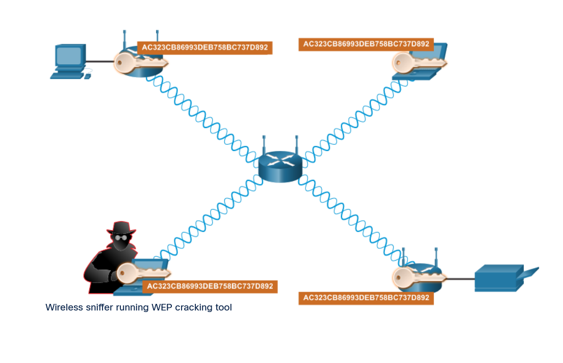
25 |
--------------------------------------------------------------------------------
/04. Data Communications and Network Services/2. IPv4 and IPv6 Address Management/3. IPv4 Issues/3. IPv4 and IPv6 Co-existence/README.md:
--------------------------------------------------------------------------------
1 | # IPv4 - IPv6 coexistence
2 |
3 | - There is no specific date to move to IPv6.
4 | - Both IPv4 and IPv6 will coexist in the near future and the transition is taking several years.
5 | - The IETF has created various protocols and tools to help network administrators migrate their networks to IPv6.
6 | - The migration techniques can be divided into three categories:
7 |
8 | 1. Dual Stack
9 |
10 | - Dual stack allows IPv4 and IPv6 to coexist on the same network segment.
11 | - Dual stack devices run both IPv4 and IPv6 protocol stacks simultaneously.
12 | - Known as native IPv6, this means the customer network has an IPv6 connection to its ISP and is able to access content found on the internet over IPv6.
13 |
14 | 
15 |
16 | 2. Tunneling
17 |
18 | - Tunneling is a method of transporting an IPv6 packet over an IPv4 network.
19 | - The IPv6 packet is encapsulated inside an IPv4 packet, similar to other types of data.
20 |
21 | 
22 |
23 | 3. Translation
24 |
25 | - Network Address Translation 64 (NAT64) allows IPv6-enabled devices to communicate with IPv4-enabled devices using a translation technique similar to NAT for IPv4.
26 | - An IPv6 packet is translated to an IPv4 packet and an IPv4 packet is translated to an IPv6 packet.
27 | - The NAT64 router translates the different IP addresses between networks (the solid line) so that the PCs with different IP addresses can communicate (the dotted line).
28 |
29 | 
30 |
--------------------------------------------------------------------------------
/01. Internet Connection/4. Clients & Servers/1. Client & Server Roles/README.md:
--------------------------------------------------------------------------------
1 | # Client and Server Roles
2 |
3 | ## Hosts
4 |
5 | - All computers connected to a network that participate directly in network communication are classified as hosts.
6 | - Hosts can send and receive messages on the network.
7 | - In modern networks, computer hosts can act as a client, a server, or both, as shown in the figure.
8 | - The software installed on the computer determines which role the computer plays.
9 |
10 | 
11 |
12 | ## Servers
13 |
14 | - Servers are hosts that have software installed which enable them to provide information, like email or web pages, to other hosts on the network.
15 | - Each service requires separate server software.
16 | - For example, a host requires web server software in order to provide web services to the network.
17 | - Every destination that you visit online is provided to you by a server located somewhere on a network that is connected to the global internet.
18 |
19 | ## Clients
20 |
21 | - Clients are computer hosts that have software installed that enables the hosts to request and display the information obtained from the server.
22 | - An example of client software is a web browser, such as Internet Explorer, Safari, Mozilla Firefox, or Chrome.
23 |
24 | | Text | Description |
25 | | --- | --- |
26 | | Email | The Email server runs the Email server software. Clients use mail server software, such as Microsoft Outlook, to access mail on the server. |
27 | | Web | Web server runs the web server software. Clients use browser software, such as Windows Internet Explorer, to access webpages on server. |
28 | | File | File server stores the corporate and user files in a central location. The client devices access these files with client software like Windows File Explorer. |
29 |
--------------------------------------------------------------------------------
/03. Network Protocols and Architecture/4. The Internet Protocol/3. IPv4 Address Structure/3. Calculate the Number of Hosts/README.md:
--------------------------------------------------------------------------------
1 | # Calculating Number of Hosts
2 |
3 | - The subnet masks we see most often with home and small business networking are: 255.0.0.0 (8-bits), 255.255.0.0 (16 bits) and 255.255.255.0 (24 bits).
4 | - A subnet mask of 255.255.255.0 (decimal) or 11111111.11111111.1111111.00000000 (binary) uses 24 bits to identify the network number which leaves 8 bits to number the hosts on that network, as shown in the figure.
5 | - To calculate the number of hosts that can be on that network, take the number 2 to the power of the number of host bits (2 ^ 8 = 256).
6 | - From this number, we must subtract 2 (256-2).
7 | - The reason we subtract 2 is that all 1s within the host portion of an IPv4 address is a broadcast address for that network and cannot be assigned to a specific host.
8 | - All 0s within the host portion indicate the network ID and again, cannot be assigned to a specific host.
9 | - Powers of 2 can be calculated easily with the calculator that comes with any Windows operating system.
10 | - Another way to determine the number of hosts available is to add up the values of the available host bits (128+64+32+16+8+4+2+1 = 255).
11 | - From this number, subtract 1 (255-1 = 254), because the host bits cannot be all 1s.
12 | - It is not necessary to subtract 2 because the value of all 0s is 0 and is not included in the addition.
13 | - With a 16-bit mask, there are 16 bits (two octets) for host addresses and a host address could have all 1s (255) in one of the octets.
14 | - This might appear to be a broadcast but as long as the other octet is not all 1s, it is a valid host address.
15 | - Remember that the host looks at all host bits together, not at octet values.
16 |
17 | 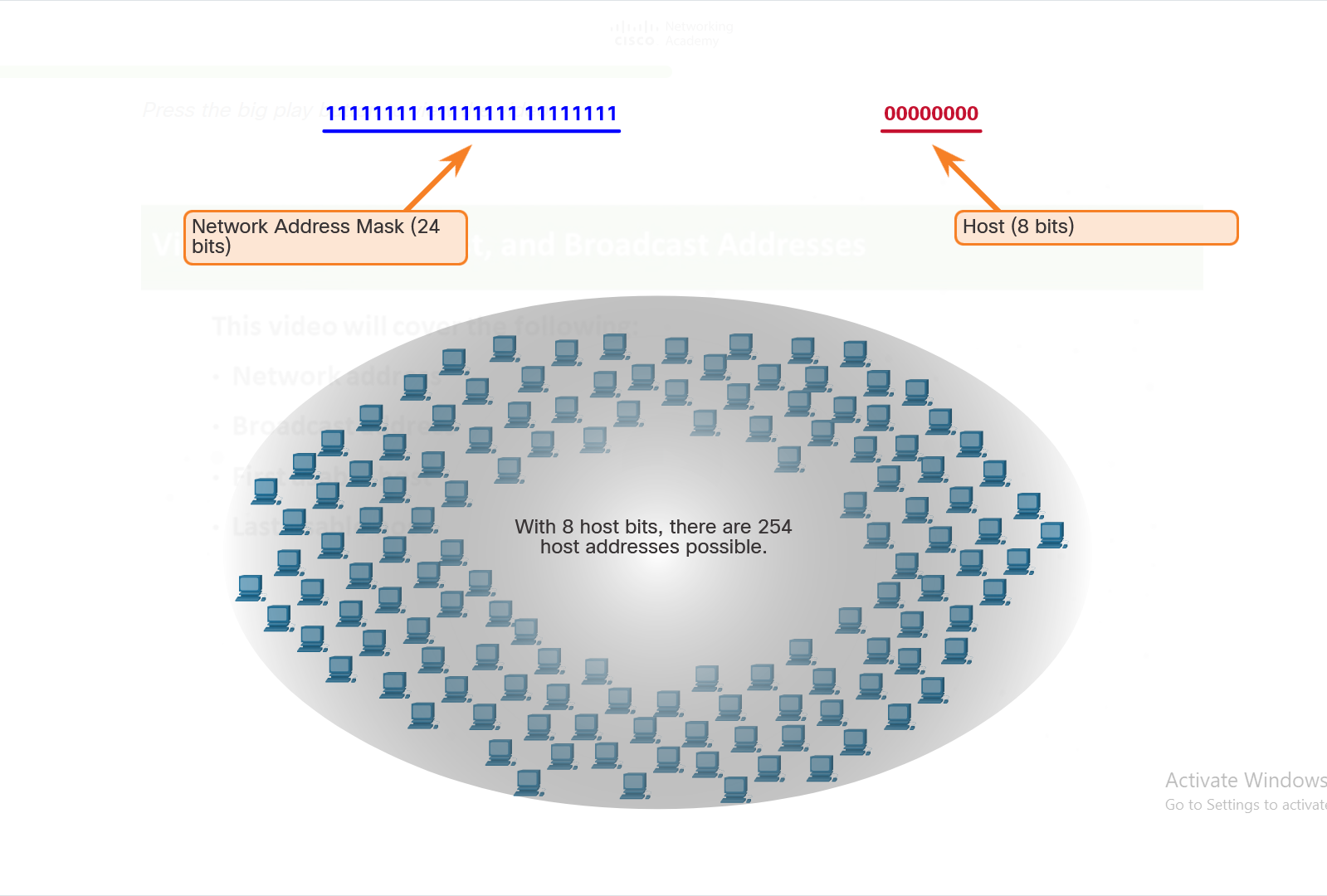
18 |
19 |
--------------------------------------------------------------------------------
/06. Connecting to Internet/1. ISP Connectivity Options/1. ISP Services/README.md:
--------------------------------------------------------------------------------
1 | # ISP Services
2 |
3 | - An Internet Service Provider (ISP) provides the link between the home network and the internet.
4 | - An ISP can be the local cable provider, a landline telephone service provider, the cellular network that provides your smart phone service, or an independent provider who leases bandwidth on the physical network infrastructure of another company.
5 |
6 | - Many ISPs also offer additional services to their contract subscribers, as shown in the figure.
7 | - These services can include email accounts, network storage, and website hosting and automated backup or security services.
8 |
9 | - ISPs are critical to communications across the global internet.
10 | - Each ISP connects to other ISPs to form a network of links that interconnect users all over the world.
11 | - ISPs are connected in a hierarchical manner that ensures that internet traffic generally takes the shortest path from the source to the destination.
12 |
13 | - The internet backbone is like an information super highway that provides high-speed data links to connect the various service provider networks in major metropolitan areas around the world.
14 | - The primary medium that connects the internet backbone is fiber-optic cable.
15 | - This cable is typically installed underground to connect cities within continents.
16 | - Fiber-optic cables also run under the sea to connect continents, countries, and cities.
17 |
18 | - The figure shows seven small circles surrounding a big circle in the center.
19 | - The big circle is labeled ISP Services.
20 | - The seven small circles are labeled FTP Hosting, Application and Media Hosting, Web Hosting, Equipment Co-Location, POP Internet Access, Voice Over IP, and Technical Support.
21 |
22 | 
23 |
24 |
--------------------------------------------------------------------------------
/06. Connecting to Internet/2. Network Virtualization/2. Types of Cloud/README.md:
--------------------------------------------------------------------------------
1 | # Types of Cloud
2 |
3 | - There are four primary cloud models,
4 |
5 | **1. Public clouds -** Cloud-based applications and services offered in a public cloud are made available to the general population.
6 | Services may be free or are offered on a pay-per-use model, such as paying for online storage.
7 | The public cloud uses the internet to provide services.
8 |
9 | **2. Private clouds -** Cloud-based applications and services offered in a private cloud are intended for a specific organization or entity, such as the government.
10 | A private cloud can be set up using the private network of an organization, though this can be expensive to build and maintain.
11 | A private cloud can also be managed by an outside organization with strict access security.
12 |
13 | **3. Hybrid clouds -** A hybrid cloud is made up of two or more clouds (example: part private, part public), where each part remains a separate object, but both are
14 | connected
15 | using a single architecture.
16 | Individuals on a hybrid cloud would be able to have degrees of access to various services based on user access rights.
17 |
18 | **4. Community clouds -** A community cloud is created for exclusive use by a specific community.
19 | The differences between public clouds and community clouds are the functional needs that have been customized for the community.
20 | For example, healthcare organizations must remain compliant with policies and laws (e.g., HIPAA) that require special authentication and
21 | confidentiality.
22 |
23 |
24 |
--------------------------------------------------------------------------------
/04. Data Communications and Network Services/2. IPv4 and IPv6 Address Management/1. Network Boundaries/2. Routers as Boundaries between Networks/README.md:
--------------------------------------------------------------------------------
1 | # Routers as Boundary Between Networks
2 |
3 | - The wireless router acts as a DHCP server for all local hosts attached to it, either by Ethernet cable or wirelessly.
4 | - These local hosts are referred to as being located on an internal, or inside, network.
5 | - Most DHCP servers are configured to assign private addresses to the hosts on the internal network, rather than internet routable public addresses.
6 | - This ensures that, by default, the internal network is not directly accessible from the internet.
7 | - The default IPv4 address configured on the local wireless router interface is usually the first host address on that network.
8 | - Internal hosts must be assigned addresses within the same network as the wireless router, either statically configured, or through DHCP.
9 | - When configured as a DHCP server, the wireless router provides addresses in this range.
10 | - It also provides the subnet mask information and its own interface IPv4 address as the default gateway, as shown in the figure.
11 | - Many ISPs also use DHCP servers to provide IPv4 addresses to the internet side of the wireless router installed at their customer sites
12 | - The network assigned to the internet side of the wireless router is referred to as the external, or outside, network.
13 | - When a wireless router is connected to the ISP, it acts like a DHCP client to receive the correct external network IPv4 address for the internet interface.
14 | - ISPs usually provide an internet-routable address, which enables hosts connected to the wireless router to have access to the internet.
15 | - The wireless router serves as the boundary between the local internal network and the external internet.
16 |
17 | 
18 |
--------------------------------------------------------------------------------
/05. Home Network Basics/3. Wireless Standards/3. Network Mode/README.md:
--------------------------------------------------------------------------------
1 | # Network Mode
2 |
3 | - The 802.11 protocol can provide increased throughput based on the wireless network environment.
4 | - If all wireless devices connect with the same 802.11 standard, maximum speeds can be obtained for that standard.
5 | - If the access point is configured to accept only one 802.11 standard, devices that do not use that standard cannot connect to the access point.
6 |
7 | - A mixed mode wireless network environment can include devices that use any of the existing Wi-Fi standards.
8 | - This environment provides easy access for older devices that need a wireless connection but do not support the latest standards.
9 |
10 | - When building a wireless network, it is important that the wireless components connect to the appropriate WLAN.
11 | - This is done using the SSID.
12 |
13 | - The SSID is a case-sensitive, alphanumeric string that contains up to 32 characters.
14 | - It is sent in the header of all frames transmitted over the WLAN.
15 | - The SSID is used to tell wireless devices, called wireless stations (STAs), which WLAN they belong to and with which other devices they can communicate.
16 |
17 | - We use the SSID to identify a specific wireless network.
18 | - It is essentially the name of the network.
19 | - Wireless routers usually broadcast their configured SSIDs by default.
20 | - The SSID broadcast allows other devices and wireless clients to automatically discover the name of the wireless network.
21 | - When the SSID broadcast is disabled, you must manually enter the SSID on wireless devices.
22 |
23 | - Disabling SSID broadcasting can make it more difficult for legitimate clients to find the wireless network. However, simply turning off the SSID broadcast is not sufficient to prevent unauthorized clients from connecting to the wireless network. All wireless networks should use the strongest available encryption to restrict unauthorized access.
24 |
--------------------------------------------------------------------------------
/03. Network Protocols and Architecture/3. Routing Between Networks/2. The Routing Table/4. The Default Gateway/README.md:
--------------------------------------------------------------------------------
1 | # Default Gateway
2 |
3 | - The method that a host uses to send messages to a destination on a remote network differs from the way a host sends messages on the same local network.
4 | - When a host needs to send a message to another host located on the same network, it will forward the message directly.
5 | - A host will use ARP to discover the MAC address of the destination host.
6 | - The IPv4 packet contains the destination IPv4 address and encapsulates the packet into a frame containing the MAC address of the destination and forwards it out.
7 | - When a host needs to send a message to a remote network, it must use the router.
8 | - The host includes the IP address of the destination host within the packet just like before.
9 | - However, when it encapsulates the packet into a frame, it uses the MAC address of the router as the destination for the frame.
10 | - In this way, the router will receive and accept the frame based on the MAC address.
11 |
12 | ## How does the source host determine the MAC address of the router?
13 |
14 | - A host is given the IPv4 address of the router through the default gateway address configured in its TCP/IP settings.
15 | - The default gateway address is the address of the router interface connected to the same local network as the source host.
16 | - All hosts on the local network use the default gateway address to send messages to the router.
17 | - When the host knows the default gateway IPv4 address, it can use ARP to determine the MAC address.
18 | - The MAC address of the router is then placed in the frame, destined for another network.
19 | - It is important that the correct default gateway be configured on each host on the local network.
20 | - If no default gateway is configured in the host TCP/IP settings, or if the wrong default gateway is specified, messages addressed to hosts on remote networks cannot be delivered.
21 |
--------------------------------------------------------------------------------
/03. Network Protocols and Architecture/4. The Internet Protocol/3. IPv4 Address Structure/1. Networks and Hosts/README.md:
--------------------------------------------------------------------------------
1 | # Networks and Hosts
2 |
3 | - The logical 32-bit IPv4 address is hierarchical and is made up of two parts, the network and the host.
4 | - In the figure, the network portion is blue, and the host portion is red.
5 | - Both parts are required in an IPv4 address. Both networks have the subnet mask 255.255.255.0.
6 | - As an example, there is a host with an IPv4 address 192.168.5.11 with a subnet mask of 255.255.255.0.
7 | - The first three octets, (192.168.5), identify the network portion of the address, and the last octet, (11) identifies the host.
8 | - This is known as hierarchical addressing because the network portion indicates the network on which each unique host address is located.
9 | - Routers only need to know how to reach each network, rather than needing to know the location of each individual host.
10 | - With IPv4 addressing, multiple logical networks can exist on one physical network, if the network portion of the logical network host addresses is different. For example:
11 | - three hosts on a single, physical local network have the same network portion of their IPv4 address (192.168.18) and three other hosts have different network portions of their IPv4 addresses (192.168.5).
12 |
13 | - The hosts with the same network number in their IPv4 addresses will be able to communicate with each other, but will not be able to communicate with the other hosts without the use of routing.
14 | - In this example, there is one physical network and two logical IPv4 networks.
15 | - Another example of a hierarchical network is the telephone system.
16 | - With a telephone number, the country code, area code and exchange represent the network address and the remaining digits represent a local phone number.
17 |
18 | 
19 |
20 |
21 |
22 |
--------------------------------------------------------------------------------
/06. Connecting to Internet/2. Network Virtualization/3. Cloud Services/README.md:
--------------------------------------------------------------------------------
1 | # Cloud Services
2 |
3 |
4 | - Cloud services are available in a variety of options, tailored to meet customer requirements. The three main cloud computing services defined by the National Institute of Standards and Technology (NIST) in their Special Publication 800-145 are as follows:
5 |
6 | **1. Software as a Service (SaaS) -** The cloud provider is responsible for access to applications and services, such as email, communication, and Microsoft 365, that are delivered over the internet.
7 | The user does not manage any aspect of the cloud services except for limited user-specific application settings.
8 | The user only needs to provide data.
9 |
10 | **2. Platform as a Service (PaaS) -** The cloud provider is responsible for providing users access to the development tools and services used to deliver the applications.
11 | These users are typically programmers and may have control over the configuration settings of the application hosting environment of the cloud provider.
12 |
13 | **3. Infrastructure as a Service (IaaS) -** The cloud provider is responsible for giving IT managers access to the network equipment, virtualized network services, and supporting network infrastructure.
14 | Using this cloud service allows IT managers to deploy and run software code, which can include operating systems and applications.
15 |
16 | - For businesses, ITaaS can extend the capability of the network without requiring investment in new infrastructure, training new personnel, or licensing new software.
17 |
18 | - These services are available on demand and delivered economically to any device anywhere in the world without compromising security or function.
19 |
20 |
21 | [Screenshot (684)](https://user-images.githubusercontent.com/63872951/175614366-7fdae476-142f-48b4-9913-511f0e5fa48c.png)
22 |
--------------------------------------------------------------------------------
/06. Connecting to Internet/1. ISP Connectivity Options/3. Cable and DSL Connections/README.md:
--------------------------------------------------------------------------------
1 | # Cable and DSL Connections
2 |
3 | Most home network users do not connect to their service providers with fiber-optic cables. The figure illustrates common connection options for small office and home users. The two most common methods are as follows:
4 |
5 | 1. Cable: - Typically offered by cable television service providers, the internet data signal is carried on the same coaxial cable that delivers cable television.
6 | - It provides a high bandwidth, always in, connection to the internet.
7 | - A special cable modem separates the internet data signal from the other signals carried on the cable and provides an Ethernet connection to a host computer or LAN.
8 |
9 | 2. DSL: - Digital Subscriber Line provides a high bandwidth, always on, connection to the internet.
10 | - It requires a special high-speed modem that separates the DSL signal from the telephone signal and provides an Ethernet connection to a host computer or LAN.
11 | - DSL runs over a telephone line, with the line split into three channels.
12 | - One channel is used for voice telephone calls.
13 | - This channel allows an individual to receive phone calls without disconnecting from the internet.
14 | - A second channel is a faster download channel, used to receive information from the internet.
15 | - The third channel is used for sending or uploading information.
16 | - This channel is usually slightly slower than the download channel.
17 | - The quality and speed of the DSL connection depends mainly on the quality of the phone line and the distance from the central office of your phone company.
18 | - The farther you are from the central office, the slower the connection.
19 |
20 | 
21 |
22 |
--------------------------------------------------------------------------------
/04. Data Communications and Network Services/3. Transport Layer Services/3. Port Numbers/3. Socket Pairs/README.md:
--------------------------------------------------------------------------------
1 | # Socket Pairs
2 |
3 | - The source and destination ports are placed within the segment.
4 | - The segments are then encapsulated within an IP packet.
5 | - The IP packet contains the IP address of the source and destination.
6 | - The combination of the source IP address and source port number, or the destination IP address and destination port number is known as a socket.
7 |
8 | 
9 |
10 |
11 | - In the example in the figure, the PC is simultaneously requesting FTP and web services from the destination server.
12 |
13 | - In the example, the FTP request generated by the PC includes the Layer 2 MAC addresses and the Layer 3 IP addresses.
14 | - The request also identifies the source port number 1305 (dynamically generated by the host) and destination port, identifying the FTP services on port 21.
15 | - The host also has requested a web page from the server using the same Layer 2 and Layer 3 addresses.
16 | - However, it is using the source port number 1099 (dynamically generated by the host) and destination port identifying the web service on port 80.
17 |
18 | - The socket is used to identify the server and service being requested by the client. A client socket might look like this, with 1099 representing the source port number: 192.168.1.5:1099
19 |
20 | - The socket on a web server might be 192.168.1.7:80
21 |
22 | - Together, these two sockets combine to form a socket pair: 192.168.1.5:1099, 192.168.1.7:80
23 |
24 | - Sockets enable multiple processes, running on a client, to distinguish themselves from each other, and multiple connections to a server process to be distinguished from each other.
25 |
26 | - The source port number acts as a return address for the requesting application.
27 | - The transport layer keeps track of this port and the application that initiated the request so that when a response is returned, it can be forwarded to the correct application.
28 |
--------------------------------------------------------------------------------
/04. Data Communications and Network Services/2. IPv4 and IPv6 Address Management/3. IPv4 Issues/1. Need for IPv6/README.md:
--------------------------------------------------------------------------------
1 | # Need for IPv6
2 |
3 | - IPv6 is designed to be the successor to IPv4.
4 | - IPv6 has a larger 128-bit address space, providing 340 undecillion (i.e., 340 followed by 36 zeroes) possible addresses.
5 | - However, IPv6 is more than just larger address space.
6 | - When the IETF began its development of a successor to IPv4, it used this opportunity to fix the limitations of IPv4 and include enhancements.
7 | - One example is Internet Control Message Protocol version 6 (ICMPv6), which includes address resolution and address autoconfiguration not found in ICMP for IPv4 (ICMPv4) IPv6 addresses.
8 | - The depletion of IPv4 address space has been the motivating factor for moving to IPv6.
9 | - As Africa, Asia and other areas of the world become more connected to the internet, there are not enough IPv4 addresses to accommodate this growth.
10 | - As shown in the figure, four out of the five RIRs have run out of IPv4 addresses.
11 | - AfriNIC will run out of IPv4 addresses very soon.
12 |
13 | 
14 |
15 | - IPv4 has a theoretical maximum of 4.3 billion addresses.
16 | - Private addresses in combination with Network Address Translation (NAT) have been instrumental in slowing the depletion of IPv4 address space.
17 | - However, NAT is problematic for many applications, creates latency, and has limitations that severely impede peer-to-peer communications.
18 | - With the ever-increasing number of mobile devices, mobile providers have been leading the way with the transition to IPv6.
19 | - The top two mobile providers in the United States report that over 90% of their traffic is over IPv6.
20 | - Most top ISPs and content providers such as YouTube, Facebook, and Netflix, have also made the transition.
21 | - Many companies like Microsoft, Facebook, and LinkedIn are transitioning to IPv6-only internally.
22 | - In 2018, broadband ISP Comcast reported a deployment of over 65% and British Sky Broadcasting over 86%.
23 |
--------------------------------------------------------------------------------