 53 |
54 | ### 1.4.2 Home Access: Cable
55 |
56 | - Cable Internet uses the existing cable TV infrastructure.
57 | - Fiber optics connect the cable head end to neighborhood junctions, then coaxial cable reaches individual homes.
58 | - Because both fiber and coaxial cable are employed in this system, it is often referred to as hybrid fiber coax (HFC).
59 | - Cable Internet requires cable modems to connect to home PCs via Ethernet.
60 | - The cable modem termination system (CMTS) turns analog signals from cable modems into digital format.
61 | - Cable Internet has downstream and upstream channels; downstream typically has higher transmission rates.
62 | - Cable Internet is a shared broadcast medium, leading to shared bandwidth.
63 | - Simultaneous usage can reduce individual user rates, but Web surfing is less affected.
64 | - The upstream channel is also shared, requiring a multiple access protocol to avoid collisions.
65 |
66 |
53 |
54 | ### 1.4.2 Home Access: Cable
55 |
56 | - Cable Internet uses the existing cable TV infrastructure.
57 | - Fiber optics connect the cable head end to neighborhood junctions, then coaxial cable reaches individual homes.
58 | - Because both fiber and coaxial cable are employed in this system, it is often referred to as hybrid fiber coax (HFC).
59 | - Cable Internet requires cable modems to connect to home PCs via Ethernet.
60 | - The cable modem termination system (CMTS) turns analog signals from cable modems into digital format.
61 | - Cable Internet has downstream and upstream channels; downstream typically has higher transmission rates.
62 | - Cable Internet is a shared broadcast medium, leading to shared bandwidth.
63 | - Simultaneous usage can reduce individual user rates, but Web surfing is less affected.
64 | - The upstream channel is also shared, requiring a multiple access protocol to avoid collisions.
65 |
66 |  67 |
68 | ### 1.4.3 Home Access: FTTH
69 |
70 | - Fiber to the home (FTTH) is a technology providing high speed residential broadband access via optical fiber.
71 | - FTTH can offer gigabit per second internet speeds.
72 | - Optical distribution networks for FTTH include direct fiber and shared fibers.
73 | - Shared fiber networks use two architectures: **active optical networks (AON)** and **passive optical networks (PON)**.
74 | - PON is used in Verizon's FiOS service and involves optical **network terminators (ONTs)** connected to a neighborhood splitter.
75 | - The splitter combines multiple homes onto a shared optical fiber, which connects to an **optical line terminator (OLT)** in the central office.
76 | - OLT connects to the internet via a telco router, and users connect their home routers to the ONT for internet access.
77 | - In the PON architecture, all packets sent from OLT to the splitter are replicated at the splitter.
78 |
79 |
80 |
67 |
68 | ### 1.4.3 Home Access: FTTH
69 |
70 | - Fiber to the home (FTTH) is a technology providing high speed residential broadband access via optical fiber.
71 | - FTTH can offer gigabit per second internet speeds.
72 | - Optical distribution networks for FTTH include direct fiber and shared fibers.
73 | - Shared fiber networks use two architectures: **active optical networks (AON)** and **passive optical networks (PON)**.
74 | - PON is used in Verizon's FiOS service and involves optical **network terminators (ONTs)** connected to a neighborhood splitter.
75 | - The splitter combines multiple homes onto a shared optical fiber, which connects to an **optical line terminator (OLT)** in the central office.
76 | - OLT connects to the internet via a telco router, and users connect their home routers to the ONT for internet access.
77 | - In the PON architecture, all packets sent from OLT to the splitter are replicated at the splitter.
78 |
79 |
80 |  81 |
82 | ### 1.4.4 Home Access: 5G Fixed Wireless
83 |
84 | - 5G fixed wireless is an emerging technology for high speed residential access.
85 | - It eliminates the need for **costly** and **unreliable cabling** from the telco's central office (CO) to homes.
86 | - Data is sent wirelessly from a provider's base station to a modem in the home using beam forming technology.
87 | - A WiFi wireless router is connected to the modem, similar to cable or DSL modem setups.
88 |
89 | ### 1.4.5 Enterprise & Home Access: Ethernet, WiFi
90 |
91 | - Ethernet is the predominant LAN technology, using twisted pair copper wire with access speeds from 100 Mbps to tens of Gbps.
92 | - Wireless LAN users connect to an access point, which is linked to the enterprise's network (usually via wired Ethernet).
93 | - IEEE 802.11 (WiFi) is widely used for wireless LAN access with shared transmission rates exceeding 100 Mbps.
94 | - Ethernet and WiFi are used not only in enterprise settings but also in home networks.
95 | - Home networks often combine broadband residential access with wireless LAN technologies.
96 |
97 | ## 1.5 Physical Media
98 |
99 | - Network access technologies in the Internet use various physical media, including fiber cable, coaxial cable, copper wire, and radio spectrum.
100 |
101 | > Physical media fall into two categories: guided media and unguided media. With guided media, the waves are guided along a solid medium, such as a fiber optic cable, a twisted pair copper wire, or a coaxial cable. With unguided media, the waves propagate in the atmosphere and in outer space, such as in a wireless LAN or a digital satellite channel.
102 |
103 | - Installation labor costs for physical links can be significantly higher than material costs, motivating builders to install multiple types of media to save on future wiring expenses.
104 | - **Twisted pair copper wire** is a common guided transmission medium, widely used in telephone networks and LANs. It consists of two insulated copper wires twisted together to **reduce interference**. Data rates for LANs range from 10 Mbps to 10 Gbps.
105 | - Twisted pair technology, like category 6a cable, can achieve data rates of 10 Gbps for short distances, making it a dominant solution for high speed LAN networking.
106 | - **Coaxial cable** consists of `two concentric copper conductors` and is commonly used in cable television systems. Coupled with cable modems, it provides high speed Internet access at rates of hundreds of Mbps.
107 | - Coaxial cable can serve as a guided shared medium, allowing multiple end systems to connect directly to the cable and receive signals sent by other end systems.
108 |
109 | > In cable television and cable Internet access, the transmitter shifts the digital signal to a specific frequency band, and the resulting analog signal is sent from the transmitter to one or more receivers.
110 |
111 | - **Optical fibers** conduct light pulses as bits and offer high data rates, low attenuation, and resistance to interference.
112 | - Fiber optics are ideal for long distance transmission but costly for short haul applications.
113 |
114 | - **Terrsetial Radio channels** are wireless and versatile, influenced by propagation environment and distance.
115 | - Three categories of terrestrial radio channels: `short range,` `local area`, and `wide area`.
116 | - Radio channel characteristics include `path loss`, `shadow fading`, `multipath fading`, and `interference`.
117 |
118 | - **Satellite communication** involves `geostationary` and `low earth orbiting (LEO)` satellites.
119 | - Geostationary satellites stay fixed above one spot on Earth but introduce signal propagation delay.
120 | - LEO satellites are closer to Earth, move in orbits, and may require multiple satellites for continuous coverage.
121 | - Satellite links offer high speeds and serve areas without DSL or cable based Internet access.
122 |
123 | ## 1.6 Packet Switching (Store and forward Transmission)
124 |
125 | - Most packet switches use **store and forward** transmission.
126 | - Packet switch must receive the entire packet before transmission.
127 |
128 | > Because the router employs store and forwarding, at this instant of time, the router cannot transmit the bits it has received; instead it must first buffer (i.e., “store”) the packet’s bits. Only after the router has received all of the packet’s bits can it begin to transmit (i.e., “forward”) the packet onto the outbound link
129 |
130 | - `Delay = 2L/R` for a simple source destination network.
131 | - General delay formula for N links each of rate R: `d = N * (L/R)`.
132 |
133 | - **Queuing Delays and Packet Loss:** Packet switches have output buffers (output queues).
134 | - Queuing delays occur when the link is busy.
135 | - Packet loss can happen when the buffer is full due to congestion.
136 |
137 | > If, during a short interval of time, the arrival rate of packets to the router (when converted to bits per second) exceeds 15 Mbps, congestion will occur at the router as packets queue in the link’s output buffer before being transmitted onto the link.
138 |
139 |
81 |
82 | ### 1.4.4 Home Access: 5G Fixed Wireless
83 |
84 | - 5G fixed wireless is an emerging technology for high speed residential access.
85 | - It eliminates the need for **costly** and **unreliable cabling** from the telco's central office (CO) to homes.
86 | - Data is sent wirelessly from a provider's base station to a modem in the home using beam forming technology.
87 | - A WiFi wireless router is connected to the modem, similar to cable or DSL modem setups.
88 |
89 | ### 1.4.5 Enterprise & Home Access: Ethernet, WiFi
90 |
91 | - Ethernet is the predominant LAN technology, using twisted pair copper wire with access speeds from 100 Mbps to tens of Gbps.
92 | - Wireless LAN users connect to an access point, which is linked to the enterprise's network (usually via wired Ethernet).
93 | - IEEE 802.11 (WiFi) is widely used for wireless LAN access with shared transmission rates exceeding 100 Mbps.
94 | - Ethernet and WiFi are used not only in enterprise settings but also in home networks.
95 | - Home networks often combine broadband residential access with wireless LAN technologies.
96 |
97 | ## 1.5 Physical Media
98 |
99 | - Network access technologies in the Internet use various physical media, including fiber cable, coaxial cable, copper wire, and radio spectrum.
100 |
101 | > Physical media fall into two categories: guided media and unguided media. With guided media, the waves are guided along a solid medium, such as a fiber optic cable, a twisted pair copper wire, or a coaxial cable. With unguided media, the waves propagate in the atmosphere and in outer space, such as in a wireless LAN or a digital satellite channel.
102 |
103 | - Installation labor costs for physical links can be significantly higher than material costs, motivating builders to install multiple types of media to save on future wiring expenses.
104 | - **Twisted pair copper wire** is a common guided transmission medium, widely used in telephone networks and LANs. It consists of two insulated copper wires twisted together to **reduce interference**. Data rates for LANs range from 10 Mbps to 10 Gbps.
105 | - Twisted pair technology, like category 6a cable, can achieve data rates of 10 Gbps for short distances, making it a dominant solution for high speed LAN networking.
106 | - **Coaxial cable** consists of `two concentric copper conductors` and is commonly used in cable television systems. Coupled with cable modems, it provides high speed Internet access at rates of hundreds of Mbps.
107 | - Coaxial cable can serve as a guided shared medium, allowing multiple end systems to connect directly to the cable and receive signals sent by other end systems.
108 |
109 | > In cable television and cable Internet access, the transmitter shifts the digital signal to a specific frequency band, and the resulting analog signal is sent from the transmitter to one or more receivers.
110 |
111 | - **Optical fibers** conduct light pulses as bits and offer high data rates, low attenuation, and resistance to interference.
112 | - Fiber optics are ideal for long distance transmission but costly for short haul applications.
113 |
114 | - **Terrsetial Radio channels** are wireless and versatile, influenced by propagation environment and distance.
115 | - Three categories of terrestrial radio channels: `short range,` `local area`, and `wide area`.
116 | - Radio channel characteristics include `path loss`, `shadow fading`, `multipath fading`, and `interference`.
117 |
118 | - **Satellite communication** involves `geostationary` and `low earth orbiting (LEO)` satellites.
119 | - Geostationary satellites stay fixed above one spot on Earth but introduce signal propagation delay.
120 | - LEO satellites are closer to Earth, move in orbits, and may require multiple satellites for continuous coverage.
121 | - Satellite links offer high speeds and serve areas without DSL or cable based Internet access.
122 |
123 | ## 1.6 Packet Switching (Store and forward Transmission)
124 |
125 | - Most packet switches use **store and forward** transmission.
126 | - Packet switch must receive the entire packet before transmission.
127 |
128 | > Because the router employs store and forwarding, at this instant of time, the router cannot transmit the bits it has received; instead it must first buffer (i.e., “store”) the packet’s bits. Only after the router has received all of the packet’s bits can it begin to transmit (i.e., “forward”) the packet onto the outbound link
129 |
130 | - `Delay = 2L/R` for a simple source destination network.
131 | - General delay formula for N links each of rate R: `d = N * (L/R)`.
132 |
133 | - **Queuing Delays and Packet Loss:** Packet switches have output buffers (output queues).
134 | - Queuing delays occur when the link is busy.
135 | - Packet loss can happen when the buffer is full due to congestion.
136 |
137 | > If, during a short interval of time, the arrival rate of packets to the router (when converted to bits per second) exceeds 15 Mbps, congestion will occur at the router as packets queue in the link’s output buffer before being transmitted onto the link.
138 |
139 |  140 |
141 | - **Forwarding Tables and Routing Protocols:** Routers use forwarding tables to determine outbound links.
142 | - IP addresses are used for destination routing.
143 | - Routers consult forwarding tables based on destination addresses.
144 | - Internet uses routing protocols to configure forwarding tables automatically.
145 |
146 | ## 1.7 Circuit Switching
147 |
148 | > In circuit switched networks, the resources needed along a path (buffers, link transmission rate) to provide for communication between the end systems are reserved for the duration of the communication session between the end systems.
149 |
150 | - Circuit switched networks reserve resources (buffers, link transmission rate) for the entire communication session, while packet switched networks use resources on demand and may involve queuing.
151 | - Traditional telephone networks are examples of circuit switched networks, where circuits are established and transmission rate is reserved for the entire connection.
152 | - **Multiplexing in circuit switched networks** can use `frequency division multiplexing (FDM)` or `time division multiplexing (TDM)`.
153 |
154 |
140 |
141 | - **Forwarding Tables and Routing Protocols:** Routers use forwarding tables to determine outbound links.
142 | - IP addresses are used for destination routing.
143 | - Routers consult forwarding tables based on destination addresses.
144 | - Internet uses routing protocols to configure forwarding tables automatically.
145 |
146 | ## 1.7 Circuit Switching
147 |
148 | > In circuit switched networks, the resources needed along a path (buffers, link transmission rate) to provide for communication between the end systems are reserved for the duration of the communication session between the end systems.
149 |
150 | - Circuit switched networks reserve resources (buffers, link transmission rate) for the entire communication session, while packet switched networks use resources on demand and may involve queuing.
151 | - Traditional telephone networks are examples of circuit switched networks, where circuits are established and transmission rate is reserved for the entire connection.
152 | - **Multiplexing in circuit switched networks** can use `frequency division multiplexing (FDM)` or `time division multiplexing (TDM)`.
153 |
154 |  155 |
156 | > FDM, the frequency domain is segmented into four bands, each of bandwidth 4 kHz. For TDM, the time domain is segmented into frames, with four time slots in each frame.
157 |
158 | - Packet switching is seen as more efficient because it doesn't reserve resources during idle periods, while circuit switching does.
159 | - Packet switching allows better sharing of transmission capacity and is simpler and more cost effective than circuit switching.
160 | - Packet switching allocates link use on demand, while circuit switching pre allocates link use regardless of demand.
161 |
162 | ## 1.8 Networks of Networks
163 |
164 | - **Network Structures:** Various network structures are discussed, including global transit ISPs, regional ISPs, and tier 1 ISPs.
165 | - **Peering:** ISPs can peer, enabling direct traffic exchange without payment. Tier 1 ISPs also peer.
166 | - **IXPs:** Internet Exchange Points facilitate ISPs' direct connections, enhancing efficiency.
167 | - **Content Provider Networks:** Large providers like Google create their networks for control and cost reduction.
168 |
169 |
155 |
156 | > FDM, the frequency domain is segmented into four bands, each of bandwidth 4 kHz. For TDM, the time domain is segmented into frames, with four time slots in each frame.
157 |
158 | - Packet switching is seen as more efficient because it doesn't reserve resources during idle periods, while circuit switching does.
159 | - Packet switching allows better sharing of transmission capacity and is simpler and more cost effective than circuit switching.
160 | - Packet switching allocates link use on demand, while circuit switching pre allocates link use regardless of demand.
161 |
162 | ## 1.8 Networks of Networks
163 |
164 | - **Network Structures:** Various network structures are discussed, including global transit ISPs, regional ISPs, and tier 1 ISPs.
165 | - **Peering:** ISPs can peer, enabling direct traffic exchange without payment. Tier 1 ISPs also peer.
166 | - **IXPs:** Internet Exchange Points facilitate ISPs' direct connections, enhancing efficiency.
167 | - **Content Provider Networks:** Large providers like Google create their networks for control and cost reduction.
168 |
169 |  170 |
171 | ## 1.9 Delay, Loss, Throughput
172 |
173 |
170 |
171 | ## 1.9 Delay, Loss, Throughput
172 |
173 |  174 |
175 | - **Types of Delays:** Several types of delays affect packets during their journey, including nodal processing delay, queuing delay, transmission delay, and propagation delay.
176 | - **Processing Delay:** Part of the processing delay includes examining the packet's header and checking for bit level errors. High speed routers have processing delays typically in microseconds.
177 | - **Queuing Delay:** Queuing delay occurs as packets wait in a queue before being transmitted onto the link. It depends on the number of packets ahead in the queue and can range from microseconds to milliseconds.
178 | - **Transmission Delay:** It is the time required to push all of a packet's bits into the link, determined by the packet's length and the transmission rate of the link. It is typically in microseconds to milliseconds.
179 | - **Propagation Delay:** It is the time for a bit to propagate from one router to the next, dependent on the distance between routers and the propagation speed of the link. It can be in milliseconds for wide area networks.
180 | - **Comparing Transmission and Propagation Delay:** Transmission delay is about pushing out the packet, while propagation delay is about bit propagation. They can be thought of as the time it takes for a caravan of cars to travel between tollbooths on a highway.
181 | - **Traffic Intensity:** The traffic intensity (La/R) plays a vital role in estimating queuing delay. If it exceeds 1, queuing delay can approach infinity. It varies based on the rate of packet arrivals and the transmission rate.
182 |
183 |
174 |
175 | - **Types of Delays:** Several types of delays affect packets during their journey, including nodal processing delay, queuing delay, transmission delay, and propagation delay.
176 | - **Processing Delay:** Part of the processing delay includes examining the packet's header and checking for bit level errors. High speed routers have processing delays typically in microseconds.
177 | - **Queuing Delay:** Queuing delay occurs as packets wait in a queue before being transmitted onto the link. It depends on the number of packets ahead in the queue and can range from microseconds to milliseconds.
178 | - **Transmission Delay:** It is the time required to push all of a packet's bits into the link, determined by the packet's length and the transmission rate of the link. It is typically in microseconds to milliseconds.
179 | - **Propagation Delay:** It is the time for a bit to propagate from one router to the next, dependent on the distance between routers and the propagation speed of the link. It can be in milliseconds for wide area networks.
180 | - **Comparing Transmission and Propagation Delay:** Transmission delay is about pushing out the packet, while propagation delay is about bit propagation. They can be thought of as the time it takes for a caravan of cars to travel between tollbooths on a highway.
181 | - **Traffic Intensity:** The traffic intensity (La/R) plays a vital role in estimating queuing delay. If it exceeds 1, queuing delay can approach infinity. It varies based on the rate of packet arrivals and the transmission rate.
182 |
183 |  184 |
185 | > **Trace Route**: measure end to end delay in a computer network by tracing the route taken by packets and measuring round-trip delays to routers.
186 |
187 | > If the source receives fewer than three messages from any given router (due to packet loss in the network), Traceroute places an asterisk just after the router number and reports fewer than three round trip times for that router.
188 |
189 | ## 1.10 Throughput
190 |
191 | > If the file consists of F bits and the transfer takes T seconds for Host B to receive all F bits, then the average throughput of the file transfer is F/T bits/sec.
192 |
193 | - **Instantaneous vs. Average Throughput**: It explains the difference between instantaneous throughput (bits/sec at a given moment) and average throughput (bits/sec over the entire transfer).
194 | - **Two Link Network**: In a simple network with two links, the throughput is determined by the slower link, which acts as the **bottleneck**. `min{Rc, Rs}`
195 | - **Multiple Links**: In a network with multiple links between source and destination, the throughput is limited by the slowest link along the path.
196 | - **Access Network**: In today's Internet, the access network is often the bottleneck for throughput due to over provisioned core network links.
197 | - **Intervening Traffic**: Throughput can be affected by other data flows sharing the same link, even if the link has a high transmission rate.
198 | - **General Dependence**: Throughput depends not only on link transmission rates but also on intervening traffic, making it a more complex concept.
199 |
200 | ## 1.11 Protocol Layers
201 |
202 | - **Protocol Layering**: Network protocols are organized into layers, with each layer providing specific services and using services from the layer below. This structure helps in the design and modularity of network protocols.
203 | - **Implementation of Layers**: Protocols can be implemented in software, hardware, or a combination of both. Application and transport layer protocols are typically implemented in software, while physical and data link layers are often implemented in hardware.
204 | - **Advantages of Layering**: Protocol layering offers modularity, making it easier to update components. It provides a structured way to discuss system components.
205 | - **Drawbacks of Layering**: Some argue against layering due to potential duplication of functionality and information dependencies between layers.
206 | - **Protocol Stack**: The protocols of different layers collectively form the protocol stack. The Internet protocol stack consists of five layers: physical, link, network, transport, and application layers.
207 | - **Encapsulation**: Data is encapsulated as it moves down the protocol stack. Each layer adds its header information to the data received from the layer above, creating a packet with header fields and a payload field.
208 |
209 | ## 1.12 Networks Under Attack
210 |
211 | - **Malware Consequences:** Malware can have severe consequences, including file deletion, data theft (e.g., passwords and personal information), and turning compromised hosts into part of botnets used for malicious purposes.
212 | - **Self Replicating Malware:** Many malware types are self replicating, meaning they can infect one host and then spread to other hosts over the Internet, leading to exponential growth in infections.
213 | - **Types of DoS Attacks:** DoS attacks can be categorized into three types: `vulnerability attacks`, `bandwidth flooding`, and `connection flooding`. These attacks disrupt services or crash hosts.
214 | - **Distributed DoS (DDoS) Attacks**: In a DDoS attack, attackers control multiple sources to launch attacks, making them harder to detect and defend against.
215 | - **Cryptography Defense**: Cryptography is one of the defenses against packet sniffing. It can help secure communication channels and protect against eavesdropping.
216 | - **IP Spoofing**: Attackers can forge source addresses on packets, allowing them to masquerade as someone else. This is known as IP spoofing and presents a security challenge.
217 | - **End Point Authentication**: To address IP spoofing and ensure message authenticity, end point authentication mechanisms are needed. These mechanisms verify the source of messages.
218 |
219 |
--------------------------------------------------------------------------------
/Chapter 2: Application Layer.md:
--------------------------------------------------------------------------------
1 | # Chapter 2: Application Layer
2 |
3 | ## 2.1 Principle of Network Applications
4 |
5 | - **Client-Server Architecture**: In a client server architecture, there is a dedicated server that services requests from multiple client hosts. Clients do not directly communicate with each other but interact with the server. The server has a fixed, well-known IP address. Examples include the Web, FTP, Telnet, and email.
6 | - **Peer-to-Peer (P2P) Architecture**: In a P2P architecture, there is minimal reliance on dedicated servers in data centers. Peers, which are intermittently connected hosts, communicate directly with each other without a dedicated server intermediary.
7 | - **P2P Scalability**: P2P architectures offer self scalability, with peers contributing service capacity by distributing files to other peers. They are cost effective and do not require significant server infrastructure.
8 | - **Challenges of P2P Architectures**: P2P applications face challenges related to security, performance, and reliability due to their highly decentralized structure.
9 | - **Communication Between Processes**: Processes running on different end systems communicate with each other by exchanging messages across the computer network.
10 | - **Socket**: Messages sent between processes must pass through the network using a software interface called a `socket`. A socket is analogous to a door through which a process sends and receives messages.
11 | - **Socket Communication**: Sockets serve as the interface between the application layer and the transport layer within a host. They are the `Application Programming Interface (API)` for building network applications.
12 |
13 |
184 |
185 | > **Trace Route**: measure end to end delay in a computer network by tracing the route taken by packets and measuring round-trip delays to routers.
186 |
187 | > If the source receives fewer than three messages from any given router (due to packet loss in the network), Traceroute places an asterisk just after the router number and reports fewer than three round trip times for that router.
188 |
189 | ## 1.10 Throughput
190 |
191 | > If the file consists of F bits and the transfer takes T seconds for Host B to receive all F bits, then the average throughput of the file transfer is F/T bits/sec.
192 |
193 | - **Instantaneous vs. Average Throughput**: It explains the difference between instantaneous throughput (bits/sec at a given moment) and average throughput (bits/sec over the entire transfer).
194 | - **Two Link Network**: In a simple network with two links, the throughput is determined by the slower link, which acts as the **bottleneck**. `min{Rc, Rs}`
195 | - **Multiple Links**: In a network with multiple links between source and destination, the throughput is limited by the slowest link along the path.
196 | - **Access Network**: In today's Internet, the access network is often the bottleneck for throughput due to over provisioned core network links.
197 | - **Intervening Traffic**: Throughput can be affected by other data flows sharing the same link, even if the link has a high transmission rate.
198 | - **General Dependence**: Throughput depends not only on link transmission rates but also on intervening traffic, making it a more complex concept.
199 |
200 | ## 1.11 Protocol Layers
201 |
202 | - **Protocol Layering**: Network protocols are organized into layers, with each layer providing specific services and using services from the layer below. This structure helps in the design and modularity of network protocols.
203 | - **Implementation of Layers**: Protocols can be implemented in software, hardware, or a combination of both. Application and transport layer protocols are typically implemented in software, while physical and data link layers are often implemented in hardware.
204 | - **Advantages of Layering**: Protocol layering offers modularity, making it easier to update components. It provides a structured way to discuss system components.
205 | - **Drawbacks of Layering**: Some argue against layering due to potential duplication of functionality and information dependencies between layers.
206 | - **Protocol Stack**: The protocols of different layers collectively form the protocol stack. The Internet protocol stack consists of five layers: physical, link, network, transport, and application layers.
207 | - **Encapsulation**: Data is encapsulated as it moves down the protocol stack. Each layer adds its header information to the data received from the layer above, creating a packet with header fields and a payload field.
208 |
209 | ## 1.12 Networks Under Attack
210 |
211 | - **Malware Consequences:** Malware can have severe consequences, including file deletion, data theft (e.g., passwords and personal information), and turning compromised hosts into part of botnets used for malicious purposes.
212 | - **Self Replicating Malware:** Many malware types are self replicating, meaning they can infect one host and then spread to other hosts over the Internet, leading to exponential growth in infections.
213 | - **Types of DoS Attacks:** DoS attacks can be categorized into three types: `vulnerability attacks`, `bandwidth flooding`, and `connection flooding`. These attacks disrupt services or crash hosts.
214 | - **Distributed DoS (DDoS) Attacks**: In a DDoS attack, attackers control multiple sources to launch attacks, making them harder to detect and defend against.
215 | - **Cryptography Defense**: Cryptography is one of the defenses against packet sniffing. It can help secure communication channels and protect against eavesdropping.
216 | - **IP Spoofing**: Attackers can forge source addresses on packets, allowing them to masquerade as someone else. This is known as IP spoofing and presents a security challenge.
217 | - **End Point Authentication**: To address IP spoofing and ensure message authenticity, end point authentication mechanisms are needed. These mechanisms verify the source of messages.
218 |
219 |
--------------------------------------------------------------------------------
/Chapter 2: Application Layer.md:
--------------------------------------------------------------------------------
1 | # Chapter 2: Application Layer
2 |
3 | ## 2.1 Principle of Network Applications
4 |
5 | - **Client-Server Architecture**: In a client server architecture, there is a dedicated server that services requests from multiple client hosts. Clients do not directly communicate with each other but interact with the server. The server has a fixed, well-known IP address. Examples include the Web, FTP, Telnet, and email.
6 | - **Peer-to-Peer (P2P) Architecture**: In a P2P architecture, there is minimal reliance on dedicated servers in data centers. Peers, which are intermittently connected hosts, communicate directly with each other without a dedicated server intermediary.
7 | - **P2P Scalability**: P2P architectures offer self scalability, with peers contributing service capacity by distributing files to other peers. They are cost effective and do not require significant server infrastructure.
8 | - **Challenges of P2P Architectures**: P2P applications face challenges related to security, performance, and reliability due to their highly decentralized structure.
9 | - **Communication Between Processes**: Processes running on different end systems communicate with each other by exchanging messages across the computer network.
10 | - **Socket**: Messages sent between processes must pass through the network using a software interface called a `socket`. A socket is analogous to a door through which a process sends and receives messages.
11 | - **Socket Communication**: Sockets serve as the interface between the application layer and the transport layer within a host. They are the `Application Programming Interface (API)` for building network applications.
12 |
13 |  14 |
15 | - **Addressing Processes**: To send messages between processes, the receiving process's address needs to be specified. This includes the host's IP address and a destination port number. The IP address identifies the host, while the port number identifies the specific receiving process.
16 | - **Port Numbers**: Popular applications are assigned specific port numbers (e.g., Web server on port 80, mail server on port 25)
17 |
18 | ## 2.2 Transport Services (TCP & UDP)
19 |
20 | - **Choosing a Transport Layer Protocol**: When developing an application, you must choose a transport layer protocol that suits your application's needs. The choice is typically based on services such as reliable data transfer, throughput, timing, and security.
21 | - **Reliable Data Transfer**: Reliable data transfer ensures that data sent by one end is delivered correctly and completely to the other end. Some applications require this service to prevent data loss, while others like multimedia apps can tolerate some loss.
22 | - **Throughput**: Throughput is the rate at which bits are delivered from the sender to the receiver in a communication session. Bandwidth sensitive applications need guaranteed throughput.
23 | - **Timing**: Timing guarantees are essential for real time applications like Internet telephony, teleconferencing, and multiplayer games. Low delay is crucial for their effectiveness.
24 | - **Security**: Transport protocols can provide security services like encryption for confidentiality, data integrity, and end-point authentication.
25 | - **UDP and TCP**: The Internet offers two transport layer protocols: UDP and TCP. UDP is lightweight and provides unreliable data transfer, while TCP offers reliable data transfer and connection oriented services.
26 | - **Services Not Provided**: Neither UDP nor TCP provide throughput or timing guarantees, which means the Internet cannot guarantee specific timing or throughput for time sensitive applications.
27 |
28 | > the Internet community has developed an enhancement for TCP, called Transport Layer Security (TLS) [RFC 5246]. TCP enhanced with TLS not only does everything that traditional TCP does but also provides critical process to process security services, including encryption, data integrity, and end point authentication.
29 |
30 | > In particular, if an application wants to use the services of TLS, it needs to include TLS code (existing, highly optimized libraries and classes) in both the client and server sides of the application. TLS has its own socket API that is similar to the traditional TCP socket API.
31 |
32 | ## 2.3 Application Layer Protocol: Web and HTTP
33 |
34 | - **HTTP**: `HTTP (HyperText Transfer Protocol)` is the primary application layer protocol of the World Wide Web. It relies on client and server programs that communicate by exchanging HTTP messages. Web pages are composed of objects, which are individual files with unique URLs.
35 | - **Web Page Structure**: A web page typically includes a base HTML file and referenced objects like images, stylesheets, and videos. Objects are identified by URLs, which consist of a `hostname` and a `path name`.
36 | - **HTTP and TCP**: HTTP uses TCP (Transmission Control Protocol) as its underlying transport protocol. Clients initiate TCP connections with servers to exchange HTTP messages.
37 |
38 | > The HTTP client first initiates a TCP connection with the server. Once the connection is established, the browser and the server processes access TCP through their socket interfaces.
39 |
40 | > HTTP need not worry about lost data or the details of how TCP recovers from loss or reordering of data within the network.
41 |
42 | - **Stateless Protocol**: HTTP is a stateless protocol, meaning servers `don't store client specific information.` If a client requests the same object multiple times, the server doesn't remember previous requests.
43 | - **HTTP Versions**: `HTTP/1.0` and `HTTP/1.1` are common versions, with HTTP/1.1 supporting persistent connections. Newer versions like HTTP/2 are also emerging.
44 | ### 2.3.1 Non Persistent and Persistent Connections
45 | - Non persistent connections create a new connection for each requested object. Persistent connections allow multiple objects to be sent over the same connection, improving efficiency.
46 |
47 | > Although HTTP uses persistent connections in its default mode, HTTP clients and servers can be configured to use non persistent connections instead.
48 |
49 | > round trip time (RTT), which is the time it takes for a small packet to travel from client to server and then back to the client. The RTT includes packet propagation delays, packet queuing delays in intermediate routers and switches, and packet processing delays.
50 |
51 |
14 |
15 | - **Addressing Processes**: To send messages between processes, the receiving process's address needs to be specified. This includes the host's IP address and a destination port number. The IP address identifies the host, while the port number identifies the specific receiving process.
16 | - **Port Numbers**: Popular applications are assigned specific port numbers (e.g., Web server on port 80, mail server on port 25)
17 |
18 | ## 2.2 Transport Services (TCP & UDP)
19 |
20 | - **Choosing a Transport Layer Protocol**: When developing an application, you must choose a transport layer protocol that suits your application's needs. The choice is typically based on services such as reliable data transfer, throughput, timing, and security.
21 | - **Reliable Data Transfer**: Reliable data transfer ensures that data sent by one end is delivered correctly and completely to the other end. Some applications require this service to prevent data loss, while others like multimedia apps can tolerate some loss.
22 | - **Throughput**: Throughput is the rate at which bits are delivered from the sender to the receiver in a communication session. Bandwidth sensitive applications need guaranteed throughput.
23 | - **Timing**: Timing guarantees are essential for real time applications like Internet telephony, teleconferencing, and multiplayer games. Low delay is crucial for their effectiveness.
24 | - **Security**: Transport protocols can provide security services like encryption for confidentiality, data integrity, and end-point authentication.
25 | - **UDP and TCP**: The Internet offers two transport layer protocols: UDP and TCP. UDP is lightweight and provides unreliable data transfer, while TCP offers reliable data transfer and connection oriented services.
26 | - **Services Not Provided**: Neither UDP nor TCP provide throughput or timing guarantees, which means the Internet cannot guarantee specific timing or throughput for time sensitive applications.
27 |
28 | > the Internet community has developed an enhancement for TCP, called Transport Layer Security (TLS) [RFC 5246]. TCP enhanced with TLS not only does everything that traditional TCP does but also provides critical process to process security services, including encryption, data integrity, and end point authentication.
29 |
30 | > In particular, if an application wants to use the services of TLS, it needs to include TLS code (existing, highly optimized libraries and classes) in both the client and server sides of the application. TLS has its own socket API that is similar to the traditional TCP socket API.
31 |
32 | ## 2.3 Application Layer Protocol: Web and HTTP
33 |
34 | - **HTTP**: `HTTP (HyperText Transfer Protocol)` is the primary application layer protocol of the World Wide Web. It relies on client and server programs that communicate by exchanging HTTP messages. Web pages are composed of objects, which are individual files with unique URLs.
35 | - **Web Page Structure**: A web page typically includes a base HTML file and referenced objects like images, stylesheets, and videos. Objects are identified by URLs, which consist of a `hostname` and a `path name`.
36 | - **HTTP and TCP**: HTTP uses TCP (Transmission Control Protocol) as its underlying transport protocol. Clients initiate TCP connections with servers to exchange HTTP messages.
37 |
38 | > The HTTP client first initiates a TCP connection with the server. Once the connection is established, the browser and the server processes access TCP through their socket interfaces.
39 |
40 | > HTTP need not worry about lost data or the details of how TCP recovers from loss or reordering of data within the network.
41 |
42 | - **Stateless Protocol**: HTTP is a stateless protocol, meaning servers `don't store client specific information.` If a client requests the same object multiple times, the server doesn't remember previous requests.
43 | - **HTTP Versions**: `HTTP/1.0` and `HTTP/1.1` are common versions, with HTTP/1.1 supporting persistent connections. Newer versions like HTTP/2 are also emerging.
44 | ### 2.3.1 Non Persistent and Persistent Connections
45 | - Non persistent connections create a new connection for each requested object. Persistent connections allow multiple objects to be sent over the same connection, improving efficiency.
46 |
47 | > Although HTTP uses persistent connections in its default mode, HTTP clients and servers can be configured to use non persistent connections instead.
48 |
49 | > round trip time (RTT), which is the time it takes for a small packet to travel from client to server and then back to the client. The RTT includes packet propagation delays, packet queuing delays in intermediate routers and switches, and packet processing delays.
50 |
51 |  52 |
53 | - The three way handshake involves the client and server exchanging messages, taking one round trip time (RTT) for this process.
54 | - After completing the handshake, the client sends an HTTP request message along with an acknowledgment into the TCP connection.
55 | - The server responds by sending the HTML file over the established connection.
56 | - The total response time is approximately two RTTs plus the transmission time for the HTML file.
57 |
58 | ### 2.3.2 HTTP Message Format:
59 |
60 | - HTTP messages have two types: `request messages` and `response messages`. Request messages include a method (e.g., GET), URL, and HTTP version, followed by header lines. Response messages include a `protocol version`, `status code` (e.g., 200 OK), and `header lines`, followed by the `entity body`. [Click here for more info](https://github.com/VasanthVanan/web-application-hackers-handbook-notes/blob/main/Chapters/Chapter-3%20Web%20Application%20Technologies.md#311-http-requests)
61 |
62 | ```http
63 | GET /somedir/page.html HTTP/1.1 \r\n
64 | Host: www.someschool.edu \r\n
65 | Connection: close \r\n
66 | User-agent: Mozilla/5.0 Accept-language: fr \r\n
67 | ```
68 |
69 | ```http
70 | HTTP/1.1 200 OK \r\n
71 | Connection: close \r\n
72 | Date: Tue, 18 Aug 2015 15:44:04 GMT \r\n
73 | Server: Apache/2.2.3 (CentOS) \r\n
74 | Last-Modified: Tue, 18 Aug 2015 15:11:03 GMT \r\n
75 | Content-Length: 6821 \r\n
76 | Content-Type: text/html \r\n
77 | \r\n
78 |
79 | (data data data data data ...)
80 | ```
81 |
82 | - **Header Lines**: Header lines provide additional information in HTTP messages. Examples of request headers include `Host`, `Connection`, `User-agent`, and `Accept-language`. Examples of response headers include `Connection`, `Date`, `Server`, `Last-Modified`, `Content-Length`, and `Content-Type`.
83 | - **Status Codes**: Status codes (e.g., 404 Not Found) indicate the result of an HTTP request. [Click here for more info](https://github.com/VasanthVanan/web-application-hackers-handbook-notes/blob/main/Chapters/Chapter-3%20Web%20Application%20Technologies.md#318-status-codes)
84 | - **HTTP Methods**: HTTP includes methods like GET, POST, PUT, and DELETE for different types of requests and actions.
85 | - **Entity Body**: The entity body in HTTP messages contains data related to the request method.
86 |
87 | ### 2.3.3 Cookies
88 |
89 | - There are situations where web sites need to identify users, for security or personalization purposes. HTTP uses cookies to achieve user identification and tracking.
90 | - Cookies have four components: a `cookie header` in HTTP `response` and `request` messages, a `cookie file` on the user's end system, and a `back end database` on the web site.
91 |
92 |
52 |
53 | - The three way handshake involves the client and server exchanging messages, taking one round trip time (RTT) for this process.
54 | - After completing the handshake, the client sends an HTTP request message along with an acknowledgment into the TCP connection.
55 | - The server responds by sending the HTML file over the established connection.
56 | - The total response time is approximately two RTTs plus the transmission time for the HTML file.
57 |
58 | ### 2.3.2 HTTP Message Format:
59 |
60 | - HTTP messages have two types: `request messages` and `response messages`. Request messages include a method (e.g., GET), URL, and HTTP version, followed by header lines. Response messages include a `protocol version`, `status code` (e.g., 200 OK), and `header lines`, followed by the `entity body`. [Click here for more info](https://github.com/VasanthVanan/web-application-hackers-handbook-notes/blob/main/Chapters/Chapter-3%20Web%20Application%20Technologies.md#311-http-requests)
61 |
62 | ```http
63 | GET /somedir/page.html HTTP/1.1 \r\n
64 | Host: www.someschool.edu \r\n
65 | Connection: close \r\n
66 | User-agent: Mozilla/5.0 Accept-language: fr \r\n
67 | ```
68 |
69 | ```http
70 | HTTP/1.1 200 OK \r\n
71 | Connection: close \r\n
72 | Date: Tue, 18 Aug 2015 15:44:04 GMT \r\n
73 | Server: Apache/2.2.3 (CentOS) \r\n
74 | Last-Modified: Tue, 18 Aug 2015 15:11:03 GMT \r\n
75 | Content-Length: 6821 \r\n
76 | Content-Type: text/html \r\n
77 | \r\n
78 |
79 | (data data data data data ...)
80 | ```
81 |
82 | - **Header Lines**: Header lines provide additional information in HTTP messages. Examples of request headers include `Host`, `Connection`, `User-agent`, and `Accept-language`. Examples of response headers include `Connection`, `Date`, `Server`, `Last-Modified`, `Content-Length`, and `Content-Type`.
83 | - **Status Codes**: Status codes (e.g., 404 Not Found) indicate the result of an HTTP request. [Click here for more info](https://github.com/VasanthVanan/web-application-hackers-handbook-notes/blob/main/Chapters/Chapter-3%20Web%20Application%20Technologies.md#318-status-codes)
84 | - **HTTP Methods**: HTTP includes methods like GET, POST, PUT, and DELETE for different types of requests and actions.
85 | - **Entity Body**: The entity body in HTTP messages contains data related to the request method.
86 |
87 | ### 2.3.3 Cookies
88 |
89 | - There are situations where web sites need to identify users, for security or personalization purposes. HTTP uses cookies to achieve user identification and tracking.
90 | - Cookies have four components: a `cookie header` in HTTP `response` and `request` messages, a `cookie file` on the user's end system, and a `back end database` on the web site.
91 |
92 |  93 |
94 | - Cookies work by sending a unique identification number in a `Set-cookie` header from the server to the user's browser.
95 | - The browser stores the identification number and sends it back to the server in a Cookie header with subsequent requests.
96 | - Cookies are used to track user activity and offer personalized services, like shopping carts or recommendations.
97 | - Users can be identified over multiple sessions by maintaining the same identification number in cookies.
98 | - Cookies are controversial due to potential privacy concerns, as websites can gather and potentially sell user information.
99 |
100 | ### 2.3.4 Web Caching
101 |
102 | - Web caches, or proxy servers, handle HTTP requests on behalf of origin servers.
103 | - Caches store copies of requested objects, reducing the need to fetch them from the origin server.
104 | - Users can configure browsers to direct requests through caches for faster responses.
105 | - Caches serve as both servers (to clients) and clients (to servers) in the caching process.
106 | - Installed by ISPs and institutions, caches enhance performance and lower bandwidth costs.
107 | - Benefits include faster responses, reduced bandwidth upgrades, and decreased overall Internet traffic.
108 | - Content Distribution Networks (CDNs) use distributed caching to localize content delivery.
109 |
110 | > An HTTP request message is a so called conditional GET message if (1) the request message uses the GET method and (2) the request message includes an If-Modified-Since: header line.
111 |
112 | - `Conditional GET` checks for freshness by comparing the `If-Modified-Since` header with object modification date.
113 | - If an object hasn't changed, a `304 Not Modified response` allows the cache to serve the locally cached object.
114 |
115 | > value of the If-modified-since: header line is exactly equal to the value of the Last-Modified: header line that was sent by the server initially.
116 |
117 | ### 2.3.5 HTTP/2
118 |
119 | > The primary goals for HTTP/2 are to reduce perceived latency by enabling request and response multiplexing over a single TCP connection, provide request prioritization and server push, and provide efficient compression of HTTP header fields.
120 |
121 | - **HTTP/2 Motivation:** HTTP/1.1's persistent TCP connections caused HOL blocking. Browsers used multiple parallel TCP connections to work around this issue.
122 |
123 | > Head of Line (HOL) blocking: occurs when a web page has a large video clip and numerous small objects. With a slow bottleneck link, the video clip causes delays for small objects queued behind it.
124 |
125 | - **HTTP/2 Solution (Framing):** Reduces the need for parallel TCP connections by breaking messages into frames and interleaving them, significantly reducing user perceived delay. Includes binary frame encoding for efficiency.
126 |
127 | > The ability to break down an HTTP message into independent frames, inter leave them, and then reassemble them on the other end is the single most important enhancement of HTTP/2.
128 |
129 | - **Message Prioritization:** Developers assign weights (1-256) to messages, and the server prioritizes higher weight responses. Clients can specify message dependencies.
130 | - **Server Push:** Enables sending additional objects to the client without explicit requests, reducing latency.
131 | - **HTTP/3 and QUIC:** QUIC, a new transport protocol over UDP and supports features like message multiplexing, is used for HTTP/3. This streamlined design incorporates HTTP/2 features and leverages QUIC's advantages.
132 |
133 | ## 2.4 Application Layer Protocol: SMTP
134 |
135 | > A typical message starts its journey in the sender’s user agent, then travels to the sender’s mail server, and then travels to the recipient’s mail server, where it is deposited in the recipient’s mailbox. Reattempts are often done every 30 minutes
136 |
137 | ### 2.4.1 Email Components
138 |
139 | - **User Agents:** Tools like Microsoft Outlook, Apple Mail, and Gmail, allowing users to manage emails.
140 | - **Mail Servers:** The central infrastructure, hosting mailboxes for recipients like Bob.
141 | - **SMTP (Simple Mail Transfer Protocol):** The principal protocol to send emails between servers.
142 |
143 | ### 2.4.2 SMTP Basics
144 |
145 | - SMTP transfers messages between sender and recipient mail servers at `Port 25`.
146 | - The client (sender's server) initiates a connection to the recipient's server via TCP.
147 |
148 | ```http
149 | S: 220 hamburger.edu
150 | C: HELO crepes.fr
151 | S: 250 Hello crepes.fr, pleased to meet you
152 | C: MAIL FROM:
93 |
94 | - Cookies work by sending a unique identification number in a `Set-cookie` header from the server to the user's browser.
95 | - The browser stores the identification number and sends it back to the server in a Cookie header with subsequent requests.
96 | - Cookies are used to track user activity and offer personalized services, like shopping carts or recommendations.
97 | - Users can be identified over multiple sessions by maintaining the same identification number in cookies.
98 | - Cookies are controversial due to potential privacy concerns, as websites can gather and potentially sell user information.
99 |
100 | ### 2.3.4 Web Caching
101 |
102 | - Web caches, or proxy servers, handle HTTP requests on behalf of origin servers.
103 | - Caches store copies of requested objects, reducing the need to fetch them from the origin server.
104 | - Users can configure browsers to direct requests through caches for faster responses.
105 | - Caches serve as both servers (to clients) and clients (to servers) in the caching process.
106 | - Installed by ISPs and institutions, caches enhance performance and lower bandwidth costs.
107 | - Benefits include faster responses, reduced bandwidth upgrades, and decreased overall Internet traffic.
108 | - Content Distribution Networks (CDNs) use distributed caching to localize content delivery.
109 |
110 | > An HTTP request message is a so called conditional GET message if (1) the request message uses the GET method and (2) the request message includes an If-Modified-Since: header line.
111 |
112 | - `Conditional GET` checks for freshness by comparing the `If-Modified-Since` header with object modification date.
113 | - If an object hasn't changed, a `304 Not Modified response` allows the cache to serve the locally cached object.
114 |
115 | > value of the If-modified-since: header line is exactly equal to the value of the Last-Modified: header line that was sent by the server initially.
116 |
117 | ### 2.3.5 HTTP/2
118 |
119 | > The primary goals for HTTP/2 are to reduce perceived latency by enabling request and response multiplexing over a single TCP connection, provide request prioritization and server push, and provide efficient compression of HTTP header fields.
120 |
121 | - **HTTP/2 Motivation:** HTTP/1.1's persistent TCP connections caused HOL blocking. Browsers used multiple parallel TCP connections to work around this issue.
122 |
123 | > Head of Line (HOL) blocking: occurs when a web page has a large video clip and numerous small objects. With a slow bottleneck link, the video clip causes delays for small objects queued behind it.
124 |
125 | - **HTTP/2 Solution (Framing):** Reduces the need for parallel TCP connections by breaking messages into frames and interleaving them, significantly reducing user perceived delay. Includes binary frame encoding for efficiency.
126 |
127 | > The ability to break down an HTTP message into independent frames, inter leave them, and then reassemble them on the other end is the single most important enhancement of HTTP/2.
128 |
129 | - **Message Prioritization:** Developers assign weights (1-256) to messages, and the server prioritizes higher weight responses. Clients can specify message dependencies.
130 | - **Server Push:** Enables sending additional objects to the client without explicit requests, reducing latency.
131 | - **HTTP/3 and QUIC:** QUIC, a new transport protocol over UDP and supports features like message multiplexing, is used for HTTP/3. This streamlined design incorporates HTTP/2 features and leverages QUIC's advantages.
132 |
133 | ## 2.4 Application Layer Protocol: SMTP
134 |
135 | > A typical message starts its journey in the sender’s user agent, then travels to the sender’s mail server, and then travels to the recipient’s mail server, where it is deposited in the recipient’s mailbox. Reattempts are often done every 30 minutes
136 |
137 | ### 2.4.1 Email Components
138 |
139 | - **User Agents:** Tools like Microsoft Outlook, Apple Mail, and Gmail, allowing users to manage emails.
140 | - **Mail Servers:** The central infrastructure, hosting mailboxes for recipients like Bob.
141 | - **SMTP (Simple Mail Transfer Protocol):** The principal protocol to send emails between servers.
142 |
143 | ### 2.4.2 SMTP Basics
144 |
145 | - SMTP transfers messages between sender and recipient mail servers at `Port 25`.
146 | - The client (sender's server) initiates a connection to the recipient's server via TCP.
147 |
148 | ```http
149 | S: 220 hamburger.edu
150 | C: HELO crepes.fr
151 | S: 250 Hello crepes.fr, pleased to meet you
152 | C: MAIL FROM:  183 |
184 | > Bob’s user agent can’t use SMTP to obtain the messages because obtaining the messages is a pull operation, whereas SMTP is a push protocol.
185 |
186 | - Users retrieve their email messages from a shared mail server using either HTTP or IMAP.
187 | - HTTP is often used for web based email clients like Gmail, while IMAP is common with clients like Microsoft Outlook.
188 | - Both the HTTP & IMAP approaches allow to manage folders, move messages to folders, delete messages, mark messages as important, and so on.
189 |
190 | ## 2.5 Application Layer Protocol: DNS
191 |
192 | - DNS is an essential service that translates human friendly hostnames into IP addresses.
193 | - It's a distributed database and an application layer protocol, implemented with `DNS servers`, often running `BIND` software and runs over UDP and uses port 53.
194 |
195 | > People prefer the more mnemonic hostname identifier, while routers prefer fixed length, hierarchically structured IP addresses.
196 |
197 | - DNS services include:
198 | - **hostname aliasing**: host with a complicated canonical hostname can have one or more alias names.
199 | ```http
200 | relay1.west-coast.enterprise.com (canonical/official website name)
201 | enterprise.com (alias name)
202 | ```
203 | - **Mail Server Aliasing**: DNS resolves alias hostnames to canonical forms for mail servers and retrieves corresponding IP addresses.
204 | ```http
205 | bob@yahoo.com --> bob@relay1.west-coast.yahoo.com
206 | ```
207 | - **Load Distribution**: DNS balances traffic among replicated servers by rotating IP addresses within replies, ensuring even distribution. This technique is also applied to email servers with shared alias names.
208 |
209 | ### 2.5.1 How DNS Works: High Level Overview
210 |
211 | > gethostbyname() is the function call that an application calls in order to perform the translation.
212 |
213 | - DNS operates through query and reply messages using UDP datagrams on port 53.
214 | - DNS queries involve multiple servers globally distributed.
215 | - A simple centralized design for DNS is not feasible due to scalability issues.
216 | - Issues with centralized design: `single point of failure,` `high traffic volume`, `distant database`, and `maintenance`.
217 | - DNS uses a hierarchical structure and a distributed database., to handle the vast number of hosts on the Internet.
218 |
219 | ### 2.5.2 Distributed, Hierarchical Database
220 |
221 |
222 |
183 |
184 | > Bob’s user agent can’t use SMTP to obtain the messages because obtaining the messages is a pull operation, whereas SMTP is a push protocol.
185 |
186 | - Users retrieve their email messages from a shared mail server using either HTTP or IMAP.
187 | - HTTP is often used for web based email clients like Gmail, while IMAP is common with clients like Microsoft Outlook.
188 | - Both the HTTP & IMAP approaches allow to manage folders, move messages to folders, delete messages, mark messages as important, and so on.
189 |
190 | ## 2.5 Application Layer Protocol: DNS
191 |
192 | - DNS is an essential service that translates human friendly hostnames into IP addresses.
193 | - It's a distributed database and an application layer protocol, implemented with `DNS servers`, often running `BIND` software and runs over UDP and uses port 53.
194 |
195 | > People prefer the more mnemonic hostname identifier, while routers prefer fixed length, hierarchically structured IP addresses.
196 |
197 | - DNS services include:
198 | - **hostname aliasing**: host with a complicated canonical hostname can have one or more alias names.
199 | ```http
200 | relay1.west-coast.enterprise.com (canonical/official website name)
201 | enterprise.com (alias name)
202 | ```
203 | - **Mail Server Aliasing**: DNS resolves alias hostnames to canonical forms for mail servers and retrieves corresponding IP addresses.
204 | ```http
205 | bob@yahoo.com --> bob@relay1.west-coast.yahoo.com
206 | ```
207 | - **Load Distribution**: DNS balances traffic among replicated servers by rotating IP addresses within replies, ensuring even distribution. This technique is also applied to email servers with shared alias names.
208 |
209 | ### 2.5.1 How DNS Works: High Level Overview
210 |
211 | > gethostbyname() is the function call that an application calls in order to perform the translation.
212 |
213 | - DNS operates through query and reply messages using UDP datagrams on port 53.
214 | - DNS queries involve multiple servers globally distributed.
215 | - A simple centralized design for DNS is not feasible due to scalability issues.
216 | - Issues with centralized design: `single point of failure,` `high traffic volume`, `distant database`, and `maintenance`.
217 | - DNS uses a hierarchical structure and a distributed database., to handle the vast number of hosts on the Internet.
218 |
219 | ### 2.5.2 Distributed, Hierarchical Database
220 |
221 |
222 |  223 |
224 | - DNS uses three classes of servers: `Root` DNS servers, `top level domain (TLD)` DNS servers, and `authoritative` DNS servers.
225 | - Root DNS servers provide IP addresses for TLD servers. TLD servers provide IP addresses for authoritative DNS servers Authoritative DNS servers store DNS records for specific organizations.
226 | - A `local DNS server`, specific to an ISP, also plays a crucial role in DNS queries. It cache DNS information to reduce query traffic and improve performance.
227 |
228 | > When a host makes a DNS query, the query is sent to the local DNS server, which acts a proxy, forwarding the query into the DNS server hierarchy.
229 |
230 | - DNS extensively utilizes caching to enhance performance. These are stored temporarily and it allows DNS servers to quickly respond to subsequent queries for the same hostname.
231 |
232 | ### 2.5.3 Recursive vs Iterative DNS Queries
233 |
234 |
223 |
224 | - DNS uses three classes of servers: `Root` DNS servers, `top level domain (TLD)` DNS servers, and `authoritative` DNS servers.
225 | - Root DNS servers provide IP addresses for TLD servers. TLD servers provide IP addresses for authoritative DNS servers Authoritative DNS servers store DNS records for specific organizations.
226 | - A `local DNS server`, specific to an ISP, also plays a crucial role in DNS queries. It cache DNS information to reduce query traffic and improve performance.
227 |
228 | > When a host makes a DNS query, the query is sent to the local DNS server, which acts a proxy, forwarding the query into the DNS server hierarchy.
229 |
230 | - DNS extensively utilizes caching to enhance performance. These are stored temporarily and it allows DNS servers to quickly respond to subsequent queries for the same hostname.
231 |
232 | ### 2.5.3 Recursive vs Iterative DNS Queries
233 |
234 |  235 |
236 | ### 2.5.4 DNS Records & Messages
237 |
238 | - DNS servers store resource records (RRs) in the distributed database.
239 | - A resource record (RR) is a four tuple: `(Name, Value, Type, TTL)`.
240 | - **TTL** (Time to Live) determines when a resource should be removed from a cache.
241 | - Types of resource records:
242 | - `Type=A`: Maps hostname to IP address.
243 | - `Type=NS`: Maps a domain to the hostname of an authoritative DNS server.
244 | - `Type=CNAME`: Provides the canonical name for an alias hostname.
245 | - `Type=MX`: Maps to the canonical name of a mail server with an alias hostname.
246 |
247 | > To obtain the canonical name for the mail server, a DNS client would query for an MX record; to obtain the canonical name for the other server, the DNS client would query for the CNAME record.
248 |
249 | - DNS messages have a header section with several fields, including `query/reply` flags, `recursion` flags, and more.
250 | - DNS messages consist of a question section, answer section (resource records), authority section, and additional section.
251 |
252 | > A 1 bit query/reply flag indicates whether the message is a query (0) or a reply (1). A 1 bit authoritative flag is set in a reply message when a DNS server is an authoritative server for a queried name.
253 |
254 | > A 1 bit recursion desired flag is set when a client (host or DNS server) desires that the DNS server perform recursion when it doesn’t have the record.
255 |
256 | > A 1 bit recursion available field is set in a reply if the DNS server supports recursion.
257 |
258 | ### 2.5.5 Inserting Records to DNS Database
259 |
260 | > A registrar is a commercial entity that verifies the uniqueness of the domain name, enters the domain name into the DNS database (as discussed below), and collects a small fee from you for its services.
261 |
262 | - To register a domain name, you need to provide registrar with DNS server names and IP addresses. Registrar enters `Type NS` and `Type A` resource records for `authoritative` DNS servers into `TLD` servers.
263 | - Additional resource records, like Type A and Type MX, must be added for Web and mail servers.
264 |
265 |
--------------------------------------------------------------------------------
/Chapter 3: Transport Layer.md:
--------------------------------------------------------------------------------
1 | # Chapter 3: Transport Layer
2 |
3 |
4 | > transport layer -- extending the network layer’s delivery service between two end systems to a delivery service between two application layer processes running on the end systems.
5 |
6 |
7 | ## 3.1 Transport-Layer Services
8 |
9 | - The transport layer resides between the application and network layers, providing communication services to application processes on different hosts.
10 | - Transport layer protocols enable `logical communication` between application processes on different hosts, abstracting the physical infrastructure.
11 | - It converts application messages into transport layer `segments`, encapsulated within network layer packets (datagrams) for transmission.
12 | - Transport protocols work only within end systems and are not involved in routing or network core activities.
13 | - These protocol provides communication between application **processes**, while network layer protocol provides communication between **hosts**.
14 |
15 | - IP makes its “best effort” to deliver segments between communicating hosts, but it makes no guarantees. (IP is said to be an unreliable service)
16 |
17 | > The most fundamental responsibility of UDP and TCP is to extend IP’s delivery service between two end systems to a delivery service between two processes running on the end systems. Extending host-to-host delivery to process-to-process delivery is called transport layer multiplexing and demultiplexing.
18 |
19 | 
20 |
21 | ### Best way to remember TCP vs UDP
22 | - Imagine two cars, each with a bouncing ball inside, driving down a slope. These cars handle the bouncing ball differently in two scenarios:
23 | #### Scenario 1: Car A – Cautious Approach
24 | - Car A is equipped with a protective shield to prevent the ball from bouncing out. The driver is extremely cautious and stops the car every time the ball moves to ensure it remains in the correct spot.
25 | > **Result**: Car A successfully reaches the bottom of the slope with the ball intact. However, the journey is slower because of frequent stops to check on the ball.
26 |
27 | #### Scenario 2: Car B – Reckless Approach
28 | - Car B lacks a protective shield and drives down the same slope at high speed. The driver is reckless and doesn’t stop to check on the ball’s position, allowing it to bounce freely and even risk flying out of the car.
29 | > **Result**: Car B reaches the bottom of the slope faster than Car A. Unfortunately, the ball gets lost along the way.
30 |
31 | 
32 |
33 | - Key Differences in UDP vs TCP Protocols:
34 |
35 | | Aspect | UDP (User Datagram Protocol) | TCP (Transmission Control Protocol) |
36 | |-----------------------------|----------------------------------|-----------------------------------------|
37 | | Service Model | Unreliable and connectionless | Reliable and connection-oriented |
38 | | Application Selection | Chosen by the application developer | Chosen by the application developer |
39 | | Terminology | Uses "datagram" for segments | Uses "segment" for segments |
40 | | Network Layer Protocol | Operates on top of IP (Internet Protocol) | Operates on top of IP (Internet Protocol) |
41 | | Services Provided | Process to process data delivery and error checking | Reliable data transfer, flow control, sequence numbers, acknowledgments, timers, and congestion control |
42 | | Reliability | Unreliable - Does not guarantee data integrity or delivery | Reliable - Ensures data delivery, integrity, and order |
43 | | Congestion Control | Unregulated - No congestion control | Regulated - Prevents excessive traffic and aims for fair sharing of network resources |
44 | | Complexity | Simpler and less complex | Complex due to additional services and mechanisms |
45 |
46 | ## 3.2 Multiplexing and Demultiplexing
47 |
48 | - **Objective**: Extend host-to-host delivery to process-to-process delivery for applications.
49 |
50 | ### Demultiplexing
51 |
52 | - Transport layer delivers data to an intermediary socket, not directly to a process.
53 | - Each socket has a unique identifier. Fields in a transport layer segment are used to identify these receiving socket.
54 | - Demultiplexing directs the segment to the corresponding socket, ensuring data is delivered to the correct process.
55 | - In the household analogy, this is similar to handing out mail to the right person based on the address.
56 |
57 | ### Multiplexing
58 |
59 | - Multiplexing involves gathering data from different sockets, encapsulating it with header information to create segments, and passing the segments to the network layer.
60 | - The transport layer in intermediate hosts performs both demultiplexing and multiplexing.
61 | - Sockets have unique identifiers. Special fields in segments identify the socket for delivery.
62 | - These fields include `source port number` and `destination port number`.
63 | - Port numbers are 16 bit numbers, ranging from 0 to 65535. The well known port numbers (0 to 1023) are reserved for established application protocols.
64 |
65 |
66 | ## 3.3 Connectionless Multiplexing and Demultiplexing
67 |
68 | - UDP sockets are automatically assigned port numbers in the range 1024 to 65535.
69 | - Servers typically assign specific port numbers, while clients often let the transport layer assign them.
70 | - Alternatively, a specific port number can be associated with a UDP socket using the `bind()` method.
71 |
72 | ```python
73 | clientSocket = socket(AF_INET, SOCK_DGRAM)
74 | clientSocket.bind((’’, 19157))
75 | ```
76 |
77 | - UDP segments have source and destination port numbers for identification.
78 | - A socket is fully identified by a `destination IP address` and a `destination port number`.
79 | - Segments are directed to the corresponding socket based on the destination port number.
80 | - If different segments have the same destination IP and destination port numbers, they go to the same destination process.
81 | - The source port number in a UDP segment serves as part of the **"return address"**. It allows the recipient to send a response back to the sender.
82 |
83 |
84 | > A-to-B segment the source port number serves as part of a “return address”—when B wants to send a segment back to A, the destination port in the B-to-A segment will take its value from the source port value of the A-to-B segment.
85 |
86 |
87 | ## 3.4 Connection Oriented Multiplexing and Demultiplexing
88 |
89 | - TCP sockets are identified by a four tuple: (source IP address, source port number, destination IP address, destination port number).
90 | - A connection establishment request includes destination and source port numbers.
91 | - Host operating systems use these values to locate the server process waiting for connections.
92 | - Server and client sockets are established and identified with four tuple values.
93 | - All subsequent segments are demultiplexed based on these four values to the correct socket.
94 |
95 |
235 |
236 | ### 2.5.4 DNS Records & Messages
237 |
238 | - DNS servers store resource records (RRs) in the distributed database.
239 | - A resource record (RR) is a four tuple: `(Name, Value, Type, TTL)`.
240 | - **TTL** (Time to Live) determines when a resource should be removed from a cache.
241 | - Types of resource records:
242 | - `Type=A`: Maps hostname to IP address.
243 | - `Type=NS`: Maps a domain to the hostname of an authoritative DNS server.
244 | - `Type=CNAME`: Provides the canonical name for an alias hostname.
245 | - `Type=MX`: Maps to the canonical name of a mail server with an alias hostname.
246 |
247 | > To obtain the canonical name for the mail server, a DNS client would query for an MX record; to obtain the canonical name for the other server, the DNS client would query for the CNAME record.
248 |
249 | - DNS messages have a header section with several fields, including `query/reply` flags, `recursion` flags, and more.
250 | - DNS messages consist of a question section, answer section (resource records), authority section, and additional section.
251 |
252 | > A 1 bit query/reply flag indicates whether the message is a query (0) or a reply (1). A 1 bit authoritative flag is set in a reply message when a DNS server is an authoritative server for a queried name.
253 |
254 | > A 1 bit recursion desired flag is set when a client (host or DNS server) desires that the DNS server perform recursion when it doesn’t have the record.
255 |
256 | > A 1 bit recursion available field is set in a reply if the DNS server supports recursion.
257 |
258 | ### 2.5.5 Inserting Records to DNS Database
259 |
260 | > A registrar is a commercial entity that verifies the uniqueness of the domain name, enters the domain name into the DNS database (as discussed below), and collects a small fee from you for its services.
261 |
262 | - To register a domain name, you need to provide registrar with DNS server names and IP addresses. Registrar enters `Type NS` and `Type A` resource records for `authoritative` DNS servers into `TLD` servers.
263 | - Additional resource records, like Type A and Type MX, must be added for Web and mail servers.
264 |
265 |
--------------------------------------------------------------------------------
/Chapter 3: Transport Layer.md:
--------------------------------------------------------------------------------
1 | # Chapter 3: Transport Layer
2 |
3 |
4 | > transport layer -- extending the network layer’s delivery service between two end systems to a delivery service between two application layer processes running on the end systems.
5 |
6 |
7 | ## 3.1 Transport-Layer Services
8 |
9 | - The transport layer resides between the application and network layers, providing communication services to application processes on different hosts.
10 | - Transport layer protocols enable `logical communication` between application processes on different hosts, abstracting the physical infrastructure.
11 | - It converts application messages into transport layer `segments`, encapsulated within network layer packets (datagrams) for transmission.
12 | - Transport protocols work only within end systems and are not involved in routing or network core activities.
13 | - These protocol provides communication between application **processes**, while network layer protocol provides communication between **hosts**.
14 |
15 | - IP makes its “best effort” to deliver segments between communicating hosts, but it makes no guarantees. (IP is said to be an unreliable service)
16 |
17 | > The most fundamental responsibility of UDP and TCP is to extend IP’s delivery service between two end systems to a delivery service between two processes running on the end systems. Extending host-to-host delivery to process-to-process delivery is called transport layer multiplexing and demultiplexing.
18 |
19 | 
20 |
21 | ### Best way to remember TCP vs UDP
22 | - Imagine two cars, each with a bouncing ball inside, driving down a slope. These cars handle the bouncing ball differently in two scenarios:
23 | #### Scenario 1: Car A – Cautious Approach
24 | - Car A is equipped with a protective shield to prevent the ball from bouncing out. The driver is extremely cautious and stops the car every time the ball moves to ensure it remains in the correct spot.
25 | > **Result**: Car A successfully reaches the bottom of the slope with the ball intact. However, the journey is slower because of frequent stops to check on the ball.
26 |
27 | #### Scenario 2: Car B – Reckless Approach
28 | - Car B lacks a protective shield and drives down the same slope at high speed. The driver is reckless and doesn’t stop to check on the ball’s position, allowing it to bounce freely and even risk flying out of the car.
29 | > **Result**: Car B reaches the bottom of the slope faster than Car A. Unfortunately, the ball gets lost along the way.
30 |
31 | 
32 |
33 | - Key Differences in UDP vs TCP Protocols:
34 |
35 | | Aspect | UDP (User Datagram Protocol) | TCP (Transmission Control Protocol) |
36 | |-----------------------------|----------------------------------|-----------------------------------------|
37 | | Service Model | Unreliable and connectionless | Reliable and connection-oriented |
38 | | Application Selection | Chosen by the application developer | Chosen by the application developer |
39 | | Terminology | Uses "datagram" for segments | Uses "segment" for segments |
40 | | Network Layer Protocol | Operates on top of IP (Internet Protocol) | Operates on top of IP (Internet Protocol) |
41 | | Services Provided | Process to process data delivery and error checking | Reliable data transfer, flow control, sequence numbers, acknowledgments, timers, and congestion control |
42 | | Reliability | Unreliable - Does not guarantee data integrity or delivery | Reliable - Ensures data delivery, integrity, and order |
43 | | Congestion Control | Unregulated - No congestion control | Regulated - Prevents excessive traffic and aims for fair sharing of network resources |
44 | | Complexity | Simpler and less complex | Complex due to additional services and mechanisms |
45 |
46 | ## 3.2 Multiplexing and Demultiplexing
47 |
48 | - **Objective**: Extend host-to-host delivery to process-to-process delivery for applications.
49 |
50 | ### Demultiplexing
51 |
52 | - Transport layer delivers data to an intermediary socket, not directly to a process.
53 | - Each socket has a unique identifier. Fields in a transport layer segment are used to identify these receiving socket.
54 | - Demultiplexing directs the segment to the corresponding socket, ensuring data is delivered to the correct process.
55 | - In the household analogy, this is similar to handing out mail to the right person based on the address.
56 |
57 | ### Multiplexing
58 |
59 | - Multiplexing involves gathering data from different sockets, encapsulating it with header information to create segments, and passing the segments to the network layer.
60 | - The transport layer in intermediate hosts performs both demultiplexing and multiplexing.
61 | - Sockets have unique identifiers. Special fields in segments identify the socket for delivery.
62 | - These fields include `source port number` and `destination port number`.
63 | - Port numbers are 16 bit numbers, ranging from 0 to 65535. The well known port numbers (0 to 1023) are reserved for established application protocols.
64 |
65 |
66 | ## 3.3 Connectionless Multiplexing and Demultiplexing
67 |
68 | - UDP sockets are automatically assigned port numbers in the range 1024 to 65535.
69 | - Servers typically assign specific port numbers, while clients often let the transport layer assign them.
70 | - Alternatively, a specific port number can be associated with a UDP socket using the `bind()` method.
71 |
72 | ```python
73 | clientSocket = socket(AF_INET, SOCK_DGRAM)
74 | clientSocket.bind((’’, 19157))
75 | ```
76 |
77 | - UDP segments have source and destination port numbers for identification.
78 | - A socket is fully identified by a `destination IP address` and a `destination port number`.
79 | - Segments are directed to the corresponding socket based on the destination port number.
80 | - If different segments have the same destination IP and destination port numbers, they go to the same destination process.
81 | - The source port number in a UDP segment serves as part of the **"return address"**. It allows the recipient to send a response back to the sender.
82 |
83 |
84 | > A-to-B segment the source port number serves as part of a “return address”—when B wants to send a segment back to A, the destination port in the B-to-A segment will take its value from the source port value of the A-to-B segment.
85 |
86 |
87 | ## 3.4 Connection Oriented Multiplexing and Demultiplexing
88 |
89 | - TCP sockets are identified by a four tuple: (source IP address, source port number, destination IP address, destination port number).
90 | - A connection establishment request includes destination and source port numbers.
91 | - Host operating systems use these values to locate the server process waiting for connections.
92 | - Server and client sockets are established and identified with four tuple values.
93 | - All subsequent segments are demultiplexed based on these four values to the correct socket.
94 |
95 |  96 |
97 | - Web servers may have multiple processes or threads to handle connections.
98 | - Each process or thread has its connection socket for receiving HTTP requests and sending responses.
99 | - High performing servers typically use one process and multiple threads or lightweight subprocesses.
100 | - One process can have many connection sockets, each with different identifiers.
101 |
102 | ### Persistent vs. Non Persistent HTTP
103 |
104 | - Persistent HTTP exchanges messages over the same server socket during a connection.
105 | - Non persistent HTTP creates and closes a new TCP connection and socket for every request/response.
106 | - Frequent socket creation and closure can impact the performance of busy Web servers.
107 |
108 | ## 3.5 UDP (User Datagram Protocol)
109 |
110 | - UDP is a minimalistic transport protocol. It provides `multiplexing`/`demultiplexing` and minimal `error checking`. Unlike TCP, it adds very little to IP.
111 |
112 | > If the application developer chooses UDP instead of TCP, then the application is almost directly talking with IP layer. UDP takes messages from the application process, attaches source and destination port number fields for the multiplexing/demultiplexing service, adds two other small fields, and passes the resulting segment to the network layer.
113 |
114 | - `Connectionless`: No handshaking between sender and receiver. Often used for `real time`, `low delay`, and `low overhead` applications.
115 | - Some applications are better suited for UDP
116 | - Allows `finer control over data sent and timing`.
117 | - `No connection establishment`, minimizing delays.
118 | - `No connection state,` supporting more active clients.
119 | - `Small packet header` overhead (UDP's 8 bytes vs. TCP's 20 bytes).
120 | - Reliability can be added to applications using UDP like QUIC protocol, but it's nontrivial. It can be built directly into the application.
121 | - Allows reliable communication without TCP's congestion control limitations.
122 | - Key fields in the UDP header:
123 | - `Port numbers`: For demultiplexing.
124 | - `Length`: Specifies the segment length (header + data).
125 | - `Checksum`: Used for error detection.
126 | - Checks for alterations during data transmission.
127 |
128 |
96 |
97 | - Web servers may have multiple processes or threads to handle connections.
98 | - Each process or thread has its connection socket for receiving HTTP requests and sending responses.
99 | - High performing servers typically use one process and multiple threads or lightweight subprocesses.
100 | - One process can have many connection sockets, each with different identifiers.
101 |
102 | ### Persistent vs. Non Persistent HTTP
103 |
104 | - Persistent HTTP exchanges messages over the same server socket during a connection.
105 | - Non persistent HTTP creates and closes a new TCP connection and socket for every request/response.
106 | - Frequent socket creation and closure can impact the performance of busy Web servers.
107 |
108 | ## 3.5 UDP (User Datagram Protocol)
109 |
110 | - UDP is a minimalistic transport protocol. It provides `multiplexing`/`demultiplexing` and minimal `error checking`. Unlike TCP, it adds very little to IP.
111 |
112 | > If the application developer chooses UDP instead of TCP, then the application is almost directly talking with IP layer. UDP takes messages from the application process, attaches source and destination port number fields for the multiplexing/demultiplexing service, adds two other small fields, and passes the resulting segment to the network layer.
113 |
114 | - `Connectionless`: No handshaking between sender and receiver. Often used for `real time`, `low delay`, and `low overhead` applications.
115 | - Some applications are better suited for UDP
116 | - Allows `finer control over data sent and timing`.
117 | - `No connection establishment`, minimizing delays.
118 | - `No connection state,` supporting more active clients.
119 | - `Small packet header` overhead (UDP's 8 bytes vs. TCP's 20 bytes).
120 | - Reliability can be added to applications using UDP like QUIC protocol, but it's nontrivial. It can be built directly into the application.
121 | - Allows reliable communication without TCP's congestion control limitations.
122 | - Key fields in the UDP header:
123 | - `Port numbers`: For demultiplexing.
124 | - `Length`: Specifies the segment length (header + data).
125 | - `Checksum`: Used for error detection.
126 | - Checks for alterations during data transmission.
127 |
128 |  129 |
130 | > UDP at the sender side performs the 1s complement of the sum of all the 16 bit words in the segment, with any overflow encountered during the sum being wrapped around.
131 |
132 |
129 |
130 | > UDP at the sender side performs the 1s complement of the sum of all the 16 bit words in the segment, with any overflow encountered during the sum being wrapped around.
131 |
132 |  133 |
134 | - Thus, the 1s complement of the sum `0100101011000010` is `1011010100111101`,
135 |
136 | > At Receiver, all the four 16 bits (3 + checksum) are added, If no errors are introduced into the packet, then clearly the sum at the receiver will be 1111111111111111. If one of the bits is a 0, then we know that errors have been introduced into the packet.
137 |
138 | > It is useful for the transport layer to provide error checking as a safety measure. Although UDP provides error checking, it does not do anything to recover from an error. Some implementations of UDP simply discard the damaged segment; others pass the damaged segment to the application with a warning.
139 |
140 | ## 3.6 Building Reliable Data Transfer Portocol
141 |
142 | ### 3.6.1 RDT 1.0:
143 | - **Basic Version:** RDT 1.0 is the most basic version of the Reliable Data Transfer protocol.
144 | - **Key Characteristics:**
145 | - Sender sends data to the receiver.
146 | - Receiver simply accepts the data without providing feedback. (unidirectional communication)
147 | - Assumes a perfectly reliable channel where data is never lost or corrupted.
148 | - No error detection or correction mechanisms in place.
149 |
150 | ### 3.6.2 RDT 2.0:
151 | - **Enhanced Reliability:** RDT 2.0 is an enhanced version of the RDT 1.0 protocol.
152 | - **Key Characteristics:**
153 | - Introduces a basic acknowledgment mechanism.
154 | - Sender sends data and waits for an `acknowledgment` (`ACK` / `NAK`) from the receiver.
155 | - Receiver sends an ACK to confirm successful data reception.
156 | - If ACK is not received, sender retransmits the data.
157 | - Addresses the issue of lost or corrupted data and ensures basic reliability.
158 |
159 | > The message dictation protocol uses both positive acknowledgments (“OK”) and negative acknowledgments (“Please repeat that.”). These control messages allow the receiver to let the sender know what has been received correctly, and what has been received in error and thus requires repeating. It is known as `ARQ (Automatic Repeat reQuest)` protocols.
160 |
161 | > when the sender is in the wait for ACK or NAK state, it cannot get more data from the upper layer; that will happen only after the sender receives an ACK and leaves this state. This is known as `Stop and Wait` protocol.
162 |
163 | ### 3.6.3 RDT 2.1:
164 | - **Extended Reliability:** RDT 2.1 further improves upon reliability.
165 | - **Key Characteristics:**
166 | - Adds a `sequence number` to each frame sent by the sender.
167 | - Receiver identifies duplicate frames and discards them.
168 | - If the receiver receives a frame with the wrong sequence number, it discards it.
169 | - This prevents duplicate frames from being delivered and enhances reliability.
170 |
171 | ### 3.6.4 RDT 3.0:
172 | - **Enhanced Error Handling:** RDT 3.0 focuses on error handling and retransmission.
173 | - **Key Characteristics:**
174 | - Similar to RDT 2.1, it uses sequence numbers to handle duplicate frames.
175 | - Introduces a `timeout mechanism`.
176 | - If the receiver doesn't receive an expected frame within a certain time (timeout), it requests retransmission.
177 | - Sender retransmits the missing frame.
178 | - Adds the ability to recover from lost frames more efficiently.
179 | - RDT 3.0 is a functionally correct protocol but has performance limitations due to its stop and wait behavior.
180 |
181 | - **Performance Example:**
182 | - Consider two hosts on the opposite coasts of the United States with a round trip propagation delay (RTT) of 30 milliseconds.
183 | - The transmission rate (R) is 1 Gbps, and the packet size (L) is 1,000 bytes.
184 | - The time needed to transmit a packet into the link is 8 microseconds (dtrans).
185 | - In a stop and wait scenario, the sender utilizes the channel very inefficiently.
186 | - Only 0.00027 of the sender's time is spent sending data into the channel, resulting in a low effective throughput, even on a high capacity link.
187 |
188 | - **Introducing Pipelining:**
189 | - The stop and wait protocol's performance is poor due to its sender utilization. It can severely limit the capabilities of high-capacity network links.
190 | - The sender can improve utilization by transmitting multiple packets before waiting for acknowledgments (`pipelining`).
191 | - This allows for a more efficient use of the channel and effectively increases sender utilization.
192 | - Introducing pipelining requires several changes:
193 | - Expanding the `range of sequence numbers` to account for multiple in transit packets.
194 | - Both sender and receiver may need to `buffer multiple packets`.
195 | - Two basic approaches for pipelined error recovery are `Go Back N` and `selective repeat`.
196 |
197 | ### 3.6.5 Go-Back-N (GBN)
198 |
199 | Animation: [Go-Back-N ARQ](https://www2.tkn.tu-berlin.de/teaching/rn/animations/gbn_sr/)
200 |
201 | > In a Go-Back-N (GBN) protocol, the sender is allowed to transmit multiple packets (when available) without waiting for an acknowledgment, but is constrained to have no more than some maximum allowable number, N, of unacknowledged packets in the pipeline.
202 |
203 |
204 | - **Sender Behavior in GBN:**
205 | - The window slides forward over the sequence number space, making N the window size.
206 | - N is referred to as the window size, and GBN is considered a sliding-window protocol.
207 | - `Flow control` and `congestion control` are some of the reasons for limiting the number of unacknowledged packets to N.
208 |
209 |
133 |
134 | - Thus, the 1s complement of the sum `0100101011000010` is `1011010100111101`,
135 |
136 | > At Receiver, all the four 16 bits (3 + checksum) are added, If no errors are introduced into the packet, then clearly the sum at the receiver will be 1111111111111111. If one of the bits is a 0, then we know that errors have been introduced into the packet.
137 |
138 | > It is useful for the transport layer to provide error checking as a safety measure. Although UDP provides error checking, it does not do anything to recover from an error. Some implementations of UDP simply discard the damaged segment; others pass the damaged segment to the application with a warning.
139 |
140 | ## 3.6 Building Reliable Data Transfer Portocol
141 |
142 | ### 3.6.1 RDT 1.0:
143 | - **Basic Version:** RDT 1.0 is the most basic version of the Reliable Data Transfer protocol.
144 | - **Key Characteristics:**
145 | - Sender sends data to the receiver.
146 | - Receiver simply accepts the data without providing feedback. (unidirectional communication)
147 | - Assumes a perfectly reliable channel where data is never lost or corrupted.
148 | - No error detection or correction mechanisms in place.
149 |
150 | ### 3.6.2 RDT 2.0:
151 | - **Enhanced Reliability:** RDT 2.0 is an enhanced version of the RDT 1.0 protocol.
152 | - **Key Characteristics:**
153 | - Introduces a basic acknowledgment mechanism.
154 | - Sender sends data and waits for an `acknowledgment` (`ACK` / `NAK`) from the receiver.
155 | - Receiver sends an ACK to confirm successful data reception.
156 | - If ACK is not received, sender retransmits the data.
157 | - Addresses the issue of lost or corrupted data and ensures basic reliability.
158 |
159 | > The message dictation protocol uses both positive acknowledgments (“OK”) and negative acknowledgments (“Please repeat that.”). These control messages allow the receiver to let the sender know what has been received correctly, and what has been received in error and thus requires repeating. It is known as `ARQ (Automatic Repeat reQuest)` protocols.
160 |
161 | > when the sender is in the wait for ACK or NAK state, it cannot get more data from the upper layer; that will happen only after the sender receives an ACK and leaves this state. This is known as `Stop and Wait` protocol.
162 |
163 | ### 3.6.3 RDT 2.1:
164 | - **Extended Reliability:** RDT 2.1 further improves upon reliability.
165 | - **Key Characteristics:**
166 | - Adds a `sequence number` to each frame sent by the sender.
167 | - Receiver identifies duplicate frames and discards them.
168 | - If the receiver receives a frame with the wrong sequence number, it discards it.
169 | - This prevents duplicate frames from being delivered and enhances reliability.
170 |
171 | ### 3.6.4 RDT 3.0:
172 | - **Enhanced Error Handling:** RDT 3.0 focuses on error handling and retransmission.
173 | - **Key Characteristics:**
174 | - Similar to RDT 2.1, it uses sequence numbers to handle duplicate frames.
175 | - Introduces a `timeout mechanism`.
176 | - If the receiver doesn't receive an expected frame within a certain time (timeout), it requests retransmission.
177 | - Sender retransmits the missing frame.
178 | - Adds the ability to recover from lost frames more efficiently.
179 | - RDT 3.0 is a functionally correct protocol but has performance limitations due to its stop and wait behavior.
180 |
181 | - **Performance Example:**
182 | - Consider two hosts on the opposite coasts of the United States with a round trip propagation delay (RTT) of 30 milliseconds.
183 | - The transmission rate (R) is 1 Gbps, and the packet size (L) is 1,000 bytes.
184 | - The time needed to transmit a packet into the link is 8 microseconds (dtrans).
185 | - In a stop and wait scenario, the sender utilizes the channel very inefficiently.
186 | - Only 0.00027 of the sender's time is spent sending data into the channel, resulting in a low effective throughput, even on a high capacity link.
187 |
188 | - **Introducing Pipelining:**
189 | - The stop and wait protocol's performance is poor due to its sender utilization. It can severely limit the capabilities of high-capacity network links.
190 | - The sender can improve utilization by transmitting multiple packets before waiting for acknowledgments (`pipelining`).
191 | - This allows for a more efficient use of the channel and effectively increases sender utilization.
192 | - Introducing pipelining requires several changes:
193 | - Expanding the `range of sequence numbers` to account for multiple in transit packets.
194 | - Both sender and receiver may need to `buffer multiple packets`.
195 | - Two basic approaches for pipelined error recovery are `Go Back N` and `selective repeat`.
196 |
197 | ### 3.6.5 Go-Back-N (GBN)
198 |
199 | Animation: [Go-Back-N ARQ](https://www2.tkn.tu-berlin.de/teaching/rn/animations/gbn_sr/)
200 |
201 | > In a Go-Back-N (GBN) protocol, the sender is allowed to transmit multiple packets (when available) without waiting for an acknowledgment, but is constrained to have no more than some maximum allowable number, N, of unacknowledged packets in the pipeline.
202 |
203 |
204 | - **Sender Behavior in GBN:**
205 | - The window slides forward over the sequence number space, making N the window size.
206 | - N is referred to as the window size, and GBN is considered a sliding-window protocol.
207 | - `Flow control` and `congestion control` are some of the reasons for limiting the number of unacknowledged packets to N.
208 |
209 |  210 |
211 | - **Sliding Window Behaviour**
212 | - Sequence numbers between `0` and `'base-1'` are for sent and acknowledged packets.
213 | - `'base'` to `'nextseqnum-1'` represents sent but unacknowledged packets.
214 | - Sequence numbers from `'nextseqnum'` to `'base+N-1'` are available for sending when data arrives.
215 | - Sequence numbers beyond `'base+N'` can't be used until unacknowledged packets are acknowledged.
216 | - GBN receiver acknowledges correctly received packets and discards out of order packets.
217 |
218 | - **Sender's Actions:**
219 | - The sender must respond to three types of events: invocation from above, receipt of an ACK, and a timeout event.
220 |
221 | > an acknowledgment for a packet with sequence number N will be taken to be a `cumulative acknowledgment`, indicating that all packets with a sequence number up to and including N have been correctly received at the receiver.
222 |
223 | - The sender checks if the window is full before sending a packet. If the window is full, data is returned to the upper layer.
224 | - If there are lost or delayed packets, a timer is used to recover them. The timer for the oldest transmitted but unacknowledged packet is managed.
225 |
226 | - **Receiver's Actions:**
227 | - The receiver handles correctly received and in-order packets by sending an ACK and delivering the data to the upper layer.
228 | - Out-of-order packets are discarded, as the receiver must deliver data in order.
229 | - Throwing away out-of-order packets simplifies receiver buffering.
230 |
231 | ### 3.6.6 Selective Repeat (SR)
232 |
233 | Animation: [Selective Repeat ARQ](https://www2.tkn.tu-berlin.de/teaching/rn/animations/gbn_sr/)
234 |
235 | - **Performance Issues with GBN:**
236 | - GBN allows the sender to fill the pipeline with packets but can suffer from performance problems, especially when the window size and bandwidth-delay product are large.
237 | - A single packet error can trigger unnecessary retransmissions, potentially filling the pipeline with these redundant packets.
238 | - Selective-repeat protocols aim to avoid unnecessary retransmissions by having the sender retransmit only suspected lost or corrupted packets.
239 | - In SR, the sender can receive ACKs for some packets in the window, unlike GBN.
240 |
241 | - **SR Sender Events and Actions:**
242 | 1. **Data Received:** Send data if it's within the window, otherwise buffer or return it.
243 | 2. **Timeout:** Use individual timers for packet retransmission.
244 | 3. **ACK Received:** Update the window and transmit new in-window packets.
245 |
246 | - **SR Receiver Events and Actions:**
247 | 1. **Packet Received:** Send selective ACKs and deliver consecutive in-window packets to the upper layer.
248 | 2. **Special Packet:** Generate ACK for correctly received packets outside the window.
249 | 3. **Other Cases:** Ignore packets not fitting the above scenarios.
250 |
251 | - **Synchronization and Implications:**
252 | - SR protocols lack synchronization between sender and receiver windows.
253 | - The finite range of sequence numbers can lead to consequences in scenarios involving packet reordering.
254 |
255 | ### 3.6.7 Improvements in RDT Protocols
256 |
257 | | Mechanism | Purpose | Comments |
258 | |--------------------|----------------------------------------------------|-----------|
259 | | Checksum | Detect bit errors in transmitted packets. | - |
260 | | Timer | Timeout for packet retransmission due to lost packets. | Duplicate packets may occur due to premature timeouts or lost ACKs. |
261 | | Sequence number | Sequential numbering for packet order and lost packet detection. | Gaps indicate lost packets; duplicates detect duplicate packets. |
262 | | Acknowledgment | Confirms correct receipt of packets. | Can be individual or cumulative, depending on the protocol. |
263 | | Negative acknowledgment (NAK) | Notifies sender about incorrectly received packets. | Typically carries the sequence number of the problematic packet. |
264 | | Window and Pipelining | Increases sender utilization by allowing multiple unacknowledged packets in the pipeline. | Window size is determined by the receiver's capacity and network congestion. |
265 |
266 |
267 | ## 3.7 TCP (Transmission Control Protocol)
268 |
269 | - **Full-Duplex and Point-to-Point:**
270 | - TCP connections provide a full-duplex service, allowing data to flow in both directions simultaneously.
271 | - Each TCP connection is between a single sender and a single receiver, and multicasting is not supported.
272 |
273 | - **Data Transfer in TCP:**
274 |
275 |
210 |
211 | - **Sliding Window Behaviour**
212 | - Sequence numbers between `0` and `'base-1'` are for sent and acknowledged packets.
213 | - `'base'` to `'nextseqnum-1'` represents sent but unacknowledged packets.
214 | - Sequence numbers from `'nextseqnum'` to `'base+N-1'` are available for sending when data arrives.
215 | - Sequence numbers beyond `'base+N'` can't be used until unacknowledged packets are acknowledged.
216 | - GBN receiver acknowledges correctly received packets and discards out of order packets.
217 |
218 | - **Sender's Actions:**
219 | - The sender must respond to three types of events: invocation from above, receipt of an ACK, and a timeout event.
220 |
221 | > an acknowledgment for a packet with sequence number N will be taken to be a `cumulative acknowledgment`, indicating that all packets with a sequence number up to and including N have been correctly received at the receiver.
222 |
223 | - The sender checks if the window is full before sending a packet. If the window is full, data is returned to the upper layer.
224 | - If there are lost or delayed packets, a timer is used to recover them. The timer for the oldest transmitted but unacknowledged packet is managed.
225 |
226 | - **Receiver's Actions:**
227 | - The receiver handles correctly received and in-order packets by sending an ACK and delivering the data to the upper layer.
228 | - Out-of-order packets are discarded, as the receiver must deliver data in order.
229 | - Throwing away out-of-order packets simplifies receiver buffering.
230 |
231 | ### 3.6.6 Selective Repeat (SR)
232 |
233 | Animation: [Selective Repeat ARQ](https://www2.tkn.tu-berlin.de/teaching/rn/animations/gbn_sr/)
234 |
235 | - **Performance Issues with GBN:**
236 | - GBN allows the sender to fill the pipeline with packets but can suffer from performance problems, especially when the window size and bandwidth-delay product are large.
237 | - A single packet error can trigger unnecessary retransmissions, potentially filling the pipeline with these redundant packets.
238 | - Selective-repeat protocols aim to avoid unnecessary retransmissions by having the sender retransmit only suspected lost or corrupted packets.
239 | - In SR, the sender can receive ACKs for some packets in the window, unlike GBN.
240 |
241 | - **SR Sender Events and Actions:**
242 | 1. **Data Received:** Send data if it's within the window, otherwise buffer or return it.
243 | 2. **Timeout:** Use individual timers for packet retransmission.
244 | 3. **ACK Received:** Update the window and transmit new in-window packets.
245 |
246 | - **SR Receiver Events and Actions:**
247 | 1. **Packet Received:** Send selective ACKs and deliver consecutive in-window packets to the upper layer.
248 | 2. **Special Packet:** Generate ACK for correctly received packets outside the window.
249 | 3. **Other Cases:** Ignore packets not fitting the above scenarios.
250 |
251 | - **Synchronization and Implications:**
252 | - SR protocols lack synchronization between sender and receiver windows.
253 | - The finite range of sequence numbers can lead to consequences in scenarios involving packet reordering.
254 |
255 | ### 3.6.7 Improvements in RDT Protocols
256 |
257 | | Mechanism | Purpose | Comments |
258 | |--------------------|----------------------------------------------------|-----------|
259 | | Checksum | Detect bit errors in transmitted packets. | - |
260 | | Timer | Timeout for packet retransmission due to lost packets. | Duplicate packets may occur due to premature timeouts or lost ACKs. |
261 | | Sequence number | Sequential numbering for packet order and lost packet detection. | Gaps indicate lost packets; duplicates detect duplicate packets. |
262 | | Acknowledgment | Confirms correct receipt of packets. | Can be individual or cumulative, depending on the protocol. |
263 | | Negative acknowledgment (NAK) | Notifies sender about incorrectly received packets. | Typically carries the sequence number of the problematic packet. |
264 | | Window and Pipelining | Increases sender utilization by allowing multiple unacknowledged packets in the pipeline. | Window size is determined by the receiver's capacity and network congestion. |
265 |
266 |
267 | ## 3.7 TCP (Transmission Control Protocol)
268 |
269 | - **Full-Duplex and Point-to-Point:**
270 | - TCP connections provide a full-duplex service, allowing data to flow in both directions simultaneously.
271 | - Each TCP connection is between a single sender and a single receiver, and multicasting is not supported.
272 |
273 | - **Data Transfer in TCP:**
274 |
275 |  276 |
277 | - Application-layer data flows from the client process to the server process.
278 | - Data is passed through the connection's `send buffer` during data transmission.
279 | - TCP controls when data is sent based on its convenience, and the `Maximum Segment Size (MSS)` limits data size.
280 |
281 | > MSS is the maximum amount of application-layer data in the segment, not the maximum size of the TCP segment including headers.
282 |
283 | > To fit within a single link-layer frame, set the MSS, considering a typical 40-byte TCP/IP header, to 1460 bytes, as Ethernet and PPP have an MTU of 1500 bytes.
284 |
285 | - Each data chunk is encapsulated in a TCP header to form TCP segments and further encapsulated in IP datagrams for network transmission.
286 | - The receiver places the received data into the connection's `receive buffer`, and the application reads the data from there.
287 |
288 | - **TCP Segment Structure:**
289 | - A TCP segment consists of `header` fields and a `data` field.
290 | - Key fields include `source port` and `destination port`, `checksum`, `sequence number`, `acknowledgment number`, `receive window`, `header length`, and `flags`.
291 | - An options field can be included for features like maximum segment size (MSS) negotiation and window scaling.
292 |
293 |
276 |
277 | - Application-layer data flows from the client process to the server process.
278 | - Data is passed through the connection's `send buffer` during data transmission.
279 | - TCP controls when data is sent based on its convenience, and the `Maximum Segment Size (MSS)` limits data size.
280 |
281 | > MSS is the maximum amount of application-layer data in the segment, not the maximum size of the TCP segment including headers.
282 |
283 | > To fit within a single link-layer frame, set the MSS, considering a typical 40-byte TCP/IP header, to 1460 bytes, as Ethernet and PPP have an MTU of 1500 bytes.
284 |
285 | - Each data chunk is encapsulated in a TCP header to form TCP segments and further encapsulated in IP datagrams for network transmission.
286 | - The receiver places the received data into the connection's `receive buffer`, and the application reads the data from there.
287 |
288 | - **TCP Segment Structure:**
289 | - A TCP segment consists of `header` fields and a `data` field.
290 | - Key fields include `source port` and `destination port`, `checksum`, `sequence number`, `acknowledgment number`, `receive window`, `header length`, and `flags`.
291 | - An options field can be included for features like maximum segment size (MSS) negotiation and window scaling.
292 |
293 |  294 |
295 |
296 | - **Sequence Numbers and Acknowledgment Numbers:**
297 | - Sequence numbers are assigned to bytes in the data stream and are included in the segment header.
298 | - Acknowledgment numbers represent the `next expected byte` in the opposite direction of data flow.
299 | - TCP uses `cumulative acknowledgments`, acknowledging the last byte received.
300 | - Handling out-of-order segments is left to TCP implementation and may involve discarding or waiting for missing bytes.
301 |
302 |
303 | ### 3.7.1 Round-Trip Time Estimation and Timeout in TCP
304 |
305 | - **Round-Trip Time Estimation:**
306 | - TCP uses round-trip time (RTT) estimation to determine the time between sending a segment and receiving an acknowledgment.
307 | - The sample RTT (`SampleRTT`) is measured for a single segment at a time, typically for one of the `unacknowledged segments`.
308 | - The SampleRTT is computed as the time between sending the segment and receiving an acknowledgment.
309 | - Multiple SampleRTT values may fluctuate due to network and load variations.
310 | - TCP calculates an average RTT, `EstimatedRTT` of `SampleRTT`, using an *exponentially weighted moving average (EWMA)* formula:
311 |
312 | ```
313 | EstimatedRTT = (1 - alpha) * EstimatedRTT + alpha * SampleRTT (alpha = 0.125)
314 | ```
315 | - EstimatedRTT gives more weight to recent samples, reflecting current network conditions.
316 |
317 | - **RTT Variation Measurement:**
318 | - TCP also measures RTT variation (`DevRTT`) to estimate how much SampleRTT deviates from EstimatedRTT.
319 | - DevRTT is calculated as an EWMA of the difference between `SampleRTT` and `EstimatedRTT`.
320 |
321 | ```
322 | DevRTT = (1 – beta) * DevRTT + beta * | SampleRTT – EstimatedRTT |
323 | ```
324 |
325 | - **Setting the Retransmission Timeout Interval:**
326 | - The retransmission timeout (TimeoutInterval) should be greater than or equal to EstimatedRTT to avoid unnecessary retransmissions.
327 | - It shouldn't be much larger than EstimatedRTT to avoid delays when retransmitting lost segments.
328 | - DevRTT plays a role in determining the timeout interval:
329 | ```
330 | TimeoutInterval = EstimatedRTT + 4 * DevRTT
331 | ```
332 | - An initial TimeoutInterval of 1 second is recommended. After a timeout, the TimeoutInterval is doubled to prevent premature timeouts for subsequent segments, but it's recomputed based on the formula afterward.
333 |
334 |
335 | ### 3.7.2 Reliable Data Transfer
336 |
337 | - **TCP Timer Management:**
338 | - An individual timer for each unacknowledged segment is conceptually simple but can have considerable overhead.
339 | - Recommended TCP timer management uses only a single retransmission timer, even for multiple unacknowledged segments.
340 | - TCP reliable data transfer is described in two steps: `timeout based recovery` and recovery using `duplicate acknowledgments`.
341 |
342 | - **Timeout and Retransmission Handling:**
343 |
344 | 1. **Data Received from Application Above:**
345 | - A TCP segment is created with a sequence number.
346 | - If the timer is not running, start the timer. The timer is associated with the oldest unacknowledged segment.
347 | - Pass the segment to IP.
348 | - Timer expiration interval is `TimeoutInterval`, calculated from `EstimatedRTT` and `DevRTT`.
349 |
350 | 2. **Timeout Event:**
351 | - Retransmit the unacknowledged segment with the smallest sequence number.
352 | - Restart the timer.
353 |
354 | 3. **ACK Received:**
355 | - On ACK with field value y, compare y with SendBase.
356 | - Update SendBase if y > SendBase.
357 | - If any unacknowledged segments remain, start the timer.
358 |
359 |
294 |
295 |
296 | - **Sequence Numbers and Acknowledgment Numbers:**
297 | - Sequence numbers are assigned to bytes in the data stream and are included in the segment header.
298 | - Acknowledgment numbers represent the `next expected byte` in the opposite direction of data flow.
299 | - TCP uses `cumulative acknowledgments`, acknowledging the last byte received.
300 | - Handling out-of-order segments is left to TCP implementation and may involve discarding or waiting for missing bytes.
301 |
302 |
303 | ### 3.7.1 Round-Trip Time Estimation and Timeout in TCP
304 |
305 | - **Round-Trip Time Estimation:**
306 | - TCP uses round-trip time (RTT) estimation to determine the time between sending a segment and receiving an acknowledgment.
307 | - The sample RTT (`SampleRTT`) is measured for a single segment at a time, typically for one of the `unacknowledged segments`.
308 | - The SampleRTT is computed as the time between sending the segment and receiving an acknowledgment.
309 | - Multiple SampleRTT values may fluctuate due to network and load variations.
310 | - TCP calculates an average RTT, `EstimatedRTT` of `SampleRTT`, using an *exponentially weighted moving average (EWMA)* formula:
311 |
312 | ```
313 | EstimatedRTT = (1 - alpha) * EstimatedRTT + alpha * SampleRTT (alpha = 0.125)
314 | ```
315 | - EstimatedRTT gives more weight to recent samples, reflecting current network conditions.
316 |
317 | - **RTT Variation Measurement:**
318 | - TCP also measures RTT variation (`DevRTT`) to estimate how much SampleRTT deviates from EstimatedRTT.
319 | - DevRTT is calculated as an EWMA of the difference between `SampleRTT` and `EstimatedRTT`.
320 |
321 | ```
322 | DevRTT = (1 – beta) * DevRTT + beta * | SampleRTT – EstimatedRTT |
323 | ```
324 |
325 | - **Setting the Retransmission Timeout Interval:**
326 | - The retransmission timeout (TimeoutInterval) should be greater than or equal to EstimatedRTT to avoid unnecessary retransmissions.
327 | - It shouldn't be much larger than EstimatedRTT to avoid delays when retransmitting lost segments.
328 | - DevRTT plays a role in determining the timeout interval:
329 | ```
330 | TimeoutInterval = EstimatedRTT + 4 * DevRTT
331 | ```
332 | - An initial TimeoutInterval of 1 second is recommended. After a timeout, the TimeoutInterval is doubled to prevent premature timeouts for subsequent segments, but it's recomputed based on the formula afterward.
333 |
334 |
335 | ### 3.7.2 Reliable Data Transfer
336 |
337 | - **TCP Timer Management:**
338 | - An individual timer for each unacknowledged segment is conceptually simple but can have considerable overhead.
339 | - Recommended TCP timer management uses only a single retransmission timer, even for multiple unacknowledged segments.
340 | - TCP reliable data transfer is described in two steps: `timeout based recovery` and recovery using `duplicate acknowledgments`.
341 |
342 | - **Timeout and Retransmission Handling:**
343 |
344 | 1. **Data Received from Application Above:**
345 | - A TCP segment is created with a sequence number.
346 | - If the timer is not running, start the timer. The timer is associated with the oldest unacknowledged segment.
347 | - Pass the segment to IP.
348 | - Timer expiration interval is `TimeoutInterval`, calculated from `EstimatedRTT` and `DevRTT`.
349 |
350 | 2. **Timeout Event:**
351 | - Retransmit the unacknowledged segment with the smallest sequence number.
352 | - Restart the timer.
353 |
354 | 3. **ACK Received:**
355 | - On ACK with field value y, compare y with SendBase.
356 | - Update SendBase if y > SendBase.
357 | - If any unacknowledged segments remain, start the timer.
358 |
359 |  360 |
361 | - **Scenarios:**
362 | - `Duplicate ACKs` can trigger a `fast retransmit` (retransmission before timeout).
363 | - TCP employs exponential back off for timer intervals.
364 | - The sender can often detect packet loss before a timeout by observing duplicate ACKs.
365 |
366 | > A duplicate ACK is an ACK that reacknowledges a segment for which the sender has already received an earlier acknowledgment.
367 |
368 | > If the TCP sender receives three duplicate ACKs for the same data, it takes this as an indication that the segment following the segment that has been ACKed three times has been lost. Then, the TCP sender performs a `fast retransmit` retransmitting the missing segment before that segment’s timer expires.
369 |
370 | - TCP's error recovery mechanism is categorized as a hybrid of `Go-Back-N (GBN)` and `Selective Repeat (SR)` protocols.
371 |
372 |
373 | ### 3.7.3 Flow Control
374 |
375 | Animation: [Flow Control](https://www2.tkn.tu-berlin.de/teaching/rn/animations/flow/)
376 |
377 | TCP Flow Control ensures that the sender doesn't overwhelm the receiver's buffer. When data arrives at the receiver, it's placed in a receive buffer, which the application reads from. If the application reads slowly, the sender can easily overflow the buffer.
378 |
379 | - **Flow Control vs. Congestion Control:**
380 | - Flow control matches sender rate to receiver reading speed.
381 | - Congestion control manages sender rate due to network congestion.
382 | - Although they both throttle the sender, they serve different purposes.
383 |
384 | - **TCP Flow Control:**
385 |
386 |
360 |
361 | - **Scenarios:**
362 | - `Duplicate ACKs` can trigger a `fast retransmit` (retransmission before timeout).
363 | - TCP employs exponential back off for timer intervals.
364 | - The sender can often detect packet loss before a timeout by observing duplicate ACKs.
365 |
366 | > A duplicate ACK is an ACK that reacknowledges a segment for which the sender has already received an earlier acknowledgment.
367 |
368 | > If the TCP sender receives three duplicate ACKs for the same data, it takes this as an indication that the segment following the segment that has been ACKed three times has been lost. Then, the TCP sender performs a `fast retransmit` retransmitting the missing segment before that segment’s timer expires.
369 |
370 | - TCP's error recovery mechanism is categorized as a hybrid of `Go-Back-N (GBN)` and `Selective Repeat (SR)` protocols.
371 |
372 |
373 | ### 3.7.3 Flow Control
374 |
375 | Animation: [Flow Control](https://www2.tkn.tu-berlin.de/teaching/rn/animations/flow/)
376 |
377 | TCP Flow Control ensures that the sender doesn't overwhelm the receiver's buffer. When data arrives at the receiver, it's placed in a receive buffer, which the application reads from. If the application reads slowly, the sender can easily overflow the buffer.
378 |
379 | - **Flow Control vs. Congestion Control:**
380 | - Flow control matches sender rate to receiver reading speed.
381 | - Congestion control manages sender rate due to network congestion.
382 | - Although they both throttle the sender, they serve different purposes.
383 |
384 | - **TCP Flow Control:**
385 |
386 |  387 |
388 | - The sender maintains a `receive window variable (rwnd)` to determine available buffer space at the receiver.
389 | - Full duplex communication means both sender and receiver have `distinct receive windows`.
390 | - rwnd is `dynamic`, and Host B informs Host A by including rwnd in its segments.
391 |
392 | ```
393 | rwnd = RcvBuffer - [LastByteRcvd - LastByteRead]
394 | ```
395 |
396 | - **Using rwnd for Flow Control:**
397 | - Host B's rwnd value reflects its available buffer space.
398 | - Host A ensures LastByteSent - LastByteAcked ≤ rwnd.
399 | - If rwnd is zero, TCP mandates that Host A sends segments with one data byte to unblock the connection.
400 | - This ensures Host A is informed when space becomes available in Host B's receive buffer.
401 |
402 | ### 3.7.4 TCP Connection Management
403 |
404 |
387 |
388 | - The sender maintains a `receive window variable (rwnd)` to determine available buffer space at the receiver.
389 | - Full duplex communication means both sender and receiver have `distinct receive windows`.
390 | - rwnd is `dynamic`, and Host B informs Host A by including rwnd in its segments.
391 |
392 | ```
393 | rwnd = RcvBuffer - [LastByteRcvd - LastByteRead]
394 | ```
395 |
396 | - **Using rwnd for Flow Control:**
397 | - Host B's rwnd value reflects its available buffer space.
398 | - Host A ensures LastByteSent - LastByteAcked ≤ rwnd.
399 | - If rwnd is zero, TCP mandates that Host A sends segments with one data byte to unblock the connection.
400 | - This ensures Host A is informed when space becomes available in Host B's receive buffer.
401 |
402 | ### 3.7.4 TCP Connection Management
403 |
404 |  405 |
406 |
407 | ## 3.8 Congestion Control
408 |
409 | - **End to End Congestion Control**
410 |
411 | In an end to end approach to congestion control, the network layer offers no explicit support to the transport layer for congestion control.
412 |
413 | > TCP segment loss (as indicated by a timeout or the receipt of three duplicate acknowledgments) is taken as an indication of network congestion, and TCP decreases its window size accordingly. Increasing round trip segment delay as an indicator of increased network congestion
414 |
415 | - **Network Assisted Congestion Control**
416 |
417 | In network assisted congestion control, routers provide explicit feedback to the sender and/or receiver regarding the network's congestion state. Feedback may range from a simple bit indicating congestion at a link to more sophisticated feedback, such as informing the sender of the maximum host sending rate a router can support.
418 |
419 | `Direct Feedback:` A network router directly sends feedback to the sender, often in the form of a choke packet indicating congestion.
420 |
421 | `Indirect Feedback:` A router marks/updates a field in a packet flowing from sender to receiver to indicate congestion. Upon receiving a marked packet, the receiver notifies the sender of the congestion indication. This method takes a full round trip time.
422 |
423 |
405 |
406 |
407 | ## 3.8 Congestion Control
408 |
409 | - **End to End Congestion Control**
410 |
411 | In an end to end approach to congestion control, the network layer offers no explicit support to the transport layer for congestion control.
412 |
413 | > TCP segment loss (as indicated by a timeout or the receipt of three duplicate acknowledgments) is taken as an indication of network congestion, and TCP decreases its window size accordingly. Increasing round trip segment delay as an indicator of increased network congestion
414 |
415 | - **Network Assisted Congestion Control**
416 |
417 | In network assisted congestion control, routers provide explicit feedback to the sender and/or receiver regarding the network's congestion state. Feedback may range from a simple bit indicating congestion at a link to more sophisticated feedback, such as informing the sender of the maximum host sending rate a router can support.
418 |
419 | `Direct Feedback:` A network router directly sends feedback to the sender, often in the form of a choke packet indicating congestion.
420 |
421 | `Indirect Feedback:` A router marks/updates a field in a packet flowing from sender to receiver to indicate congestion. Upon receiving a marked packet, the receiver notifies the sender of the congestion indication. This method takes a full round trip time.
422 |
423 |  424 |
425 |
426 | ### 3.8.1 Classic TCP Congestion Control
427 |
428 | TCP adopts an approach where each sender limits the rate of sending traffic into its connection based on perceived network congestion. This raises questions about how the sender limits its rate, how it perceives congestion, and the algorithm used to adjust its rate.
429 |
430 | - **Rate Limiting Mechanism**
431 |
432 | TCP sender limits the rate using a `congestion window (cwnd)` variable, constraining the amount of unacknowledged data. The constraint is given by:
433 |
434 | ```
435 | LastByteSent - LastByteAcked <= min (cwnd, rwnd)
436 | ```
437 |
438 | Assuming a large receive buffer, the constraint solely depends on cwnd, limiting the sender's rate. The sender adjusts cwnd to control its sending rate based on network conditions.
439 |
440 | > Thus the sender’s send rate is roughly `cwnd/RTT bytes/sec`. By adjusting the value of cwnd, the sender can therefore adjust the rate at which it sends data into its connection.
441 |
442 | - **Perceiving Congestion**
443 |
444 | TCP perceives congestion through loss events, defined as either a timeout or three duplicate ACKs. Excessive congestion causes router buffers to overflow, resulting in dropped datagrams, triggering a loss event at the sender. In a congestion free network, acknowledgments for unacknowledged segments arrive, signaling successful delivery and leading to an increase in cwnd.
445 |
446 | - **Determining Sending Rate**
447 |
448 | TCP addresses the challenge of determining the sending rate to avoid network congestion while utilizing available bandwidth. It follows guiding principles:
449 | - **Loss Event:** A lost segment implies congestion, decreasing the sender's rate.
450 | - **Acknowledged Segment:** Acknowledgments indicate successful delivery, allowing an increase in the sender's rate.
451 | - **Bandwidth Probing:** TCP probes for congestion onset by increasing the rate until a loss event occurs, adjusting the transmission rate based on implicit signals.
452 |
453 | > The TCP sender thus increases its transmission rate to probe for the rate that at which congestion onset begins, backs off from that rate, and then to begins probing again to see if the congestion onset rate has changed.
454 |
455 | - **TCP Congestion Control Algorithm**
456 |
457 | The TCP congestion control algorithm, standardized in [RFC 5681], consists of three major components:
458 |
459 | 1. **Slow Start:** Initially, cwnd is small, and the sending rate doubles each round until a threshold is reached or a loss event occurs. Slow start ends on loss, setting cwnd to 1 MSS, and transitions to congestion avoidance.
460 |
461 | 2. **Congestion Avoidance:** Linear increase of cwnd by 1 MSS per round, avoiding aggressive growth. Ends on loss, similar to slow start.
462 |
463 | > TCP’s congestion avoidance algorithm behaves the same when a timeout occurs as in the case of slow start: The value of cwnd is set to 1 MSS, and the value of ssthresh is updated to half the value of cwnd when the loss event occurred.
464 |
465 | 3. **Fast Recovery:** Recommended but not required. It involves increasing cwnd for duplicate ACKs and transitioning to congestion avoidance on ACK for the missing segment.
466 |
467 | > TCP Tahoe, unconditionally cut its congestion window to 1 MSS and entered the slow start phase after either a timeout indicated or triple duplicate ACK indicated loss event. The newer version of TCP, TCP Reno, incorporated fast recovery.
468 |
469 |
424 |
425 |
426 | ### 3.8.1 Classic TCP Congestion Control
427 |
428 | TCP adopts an approach where each sender limits the rate of sending traffic into its connection based on perceived network congestion. This raises questions about how the sender limits its rate, how it perceives congestion, and the algorithm used to adjust its rate.
429 |
430 | - **Rate Limiting Mechanism**
431 |
432 | TCP sender limits the rate using a `congestion window (cwnd)` variable, constraining the amount of unacknowledged data. The constraint is given by:
433 |
434 | ```
435 | LastByteSent - LastByteAcked <= min (cwnd, rwnd)
436 | ```
437 |
438 | Assuming a large receive buffer, the constraint solely depends on cwnd, limiting the sender's rate. The sender adjusts cwnd to control its sending rate based on network conditions.
439 |
440 | > Thus the sender’s send rate is roughly `cwnd/RTT bytes/sec`. By adjusting the value of cwnd, the sender can therefore adjust the rate at which it sends data into its connection.
441 |
442 | - **Perceiving Congestion**
443 |
444 | TCP perceives congestion through loss events, defined as either a timeout or three duplicate ACKs. Excessive congestion causes router buffers to overflow, resulting in dropped datagrams, triggering a loss event at the sender. In a congestion free network, acknowledgments for unacknowledged segments arrive, signaling successful delivery and leading to an increase in cwnd.
445 |
446 | - **Determining Sending Rate**
447 |
448 | TCP addresses the challenge of determining the sending rate to avoid network congestion while utilizing available bandwidth. It follows guiding principles:
449 | - **Loss Event:** A lost segment implies congestion, decreasing the sender's rate.
450 | - **Acknowledged Segment:** Acknowledgments indicate successful delivery, allowing an increase in the sender's rate.
451 | - **Bandwidth Probing:** TCP probes for congestion onset by increasing the rate until a loss event occurs, adjusting the transmission rate based on implicit signals.
452 |
453 | > The TCP sender thus increases its transmission rate to probe for the rate that at which congestion onset begins, backs off from that rate, and then to begins probing again to see if the congestion onset rate has changed.
454 |
455 | - **TCP Congestion Control Algorithm**
456 |
457 | The TCP congestion control algorithm, standardized in [RFC 5681], consists of three major components:
458 |
459 | 1. **Slow Start:** Initially, cwnd is small, and the sending rate doubles each round until a threshold is reached or a loss event occurs. Slow start ends on loss, setting cwnd to 1 MSS, and transitions to congestion avoidance.
460 |
461 | 2. **Congestion Avoidance:** Linear increase of cwnd by 1 MSS per round, avoiding aggressive growth. Ends on loss, similar to slow start.
462 |
463 | > TCP’s congestion avoidance algorithm behaves the same when a timeout occurs as in the case of slow start: The value of cwnd is set to 1 MSS, and the value of ssthresh is updated to half the value of cwnd when the loss event occurred.
464 |
465 | 3. **Fast Recovery:** Recommended but not required. It involves increasing cwnd for duplicate ACKs and transitioning to congestion avoidance on ACK for the missing segment.
466 |
467 | > TCP Tahoe, unconditionally cut its congestion window to 1 MSS and entered the slow start phase after either a timeout indicated or triple duplicate ACK indicated loss event. The newer version of TCP, TCP Reno, incorporated fast recovery.
468 |
469 |  470 |
471 | TCP's congestion control exhibits `saw tooth` behavior, referred to as `additive increase, multiplicative decrease` **(AIMD)**. AIMD aims to simultaneously optimize user and network performance, probing for available bandwidth in an asynchronous manner.
472 |
473 |
474 | ## 3.9 Network Assisted Congestions
475 |
476 | ### 3.9.1 Explicit Congestion Notification
477 |
478 |
470 |
471 | TCP's congestion control exhibits `saw tooth` behavior, referred to as `additive increase, multiplicative decrease` **(AIMD)**. AIMD aims to simultaneously optimize user and network performance, probing for available bandwidth in an asynchronous manner.
472 |
473 |
474 | ## 3.9 Network Assisted Congestions
475 |
476 | ### 3.9.1 Explicit Congestion Notification
477 |
478 |  479 |
480 | - ECN is a form of network assisted congestion control in the Internet that involves both TCP and IP.
481 | - Two bits in the IP datagram header's `Type of Service` field are reserved for `ECN`.
482 | - One ECN setting indicates router `congestion`; the other indicates ECN `capability of sender and receiver`.
483 | - Router congestion indication is forwarded to the destination host, informing the sending host.
484 | - TCP sender reacts to ECN congestion indication by halving the congestion window and setting the CWR bit.
485 | - Other transport layer protocols, including DCCP, DCTCP, and DCQCN, also use ECN.
486 | - Increasing deployment of ECN capabilities in popular servers and routers.
487 |
488 | ### 3.9.2 Delay based Congestion Control
489 |
490 | - Proactively detects congestion onset before packet loss.
491 | - TCP Vegas measures RTT for acknowledged packets and adjusts the congestion window based on throughput.
492 | - TCP Vegas operates under the intuition that TCP senders should “Keep the pipe just full, but no fuller”
493 | - BBR congestion control builds on TCP Vegas ideas, competing fairly with non BBR TCP senders.
494 | - Google adopted BBR for all TCP traffic on its private B4 network, replacing CUBIC.
495 |
496 |
497 | ## 3.10 Evolution of Transport Layer Functionality
498 |
499 | The design and implementation of transport layer functionality has continued to evolve.
500 |
501 | - Various versions of TCP developed, implemented, and deployed, including TCP CUBIC, DCTCP, CTCP, BBR, and more.
502 | - Measurements indicate wider deployment of newer TCP versions on Web servers than classic TCP Reno.
503 | - Many versions of TCP designed for specific conditions, such as wireless links, high bandwidth paths, paths with packet re-ordering, and more.
504 | - Diversity in TCP versions handling priorities, parallel paths, acknowledgment, and session establishment/closure.
505 | - Survey of TCP versions available in [Afanasyev 2010] and [Narayan 2018].
506 |
507 | - **QUIC: Quick UDP Internet Connections**
508 |
509 | If the transport services needed by an application don’t quite fit either the UDP or TCP service models, application designers can create their own protocol at the application layer. This approach is taken in the QUIC (Quick UDP Internet Connections) protocol
510 |
511 | - QUIC is an application layer protocol designed to improve the performance of transport layer services for secure HTTP.
512 | - Widely deployed, still in the process of being standardized as an Internet.
513 | - Google has deployed QUIC on many public facing Web servers, in its mobile video streaming YouTube app, in its Chrome browser, and in Android’s Google Search app.
514 |
515 |
479 |
480 | - ECN is a form of network assisted congestion control in the Internet that involves both TCP and IP.
481 | - Two bits in the IP datagram header's `Type of Service` field are reserved for `ECN`.
482 | - One ECN setting indicates router `congestion`; the other indicates ECN `capability of sender and receiver`.
483 | - Router congestion indication is forwarded to the destination host, informing the sending host.
484 | - TCP sender reacts to ECN congestion indication by halving the congestion window and setting the CWR bit.
485 | - Other transport layer protocols, including DCCP, DCTCP, and DCQCN, also use ECN.
486 | - Increasing deployment of ECN capabilities in popular servers and routers.
487 |
488 | ### 3.9.2 Delay based Congestion Control
489 |
490 | - Proactively detects congestion onset before packet loss.
491 | - TCP Vegas measures RTT for acknowledged packets and adjusts the congestion window based on throughput.
492 | - TCP Vegas operates under the intuition that TCP senders should “Keep the pipe just full, but no fuller”
493 | - BBR congestion control builds on TCP Vegas ideas, competing fairly with non BBR TCP senders.
494 | - Google adopted BBR for all TCP traffic on its private B4 network, replacing CUBIC.
495 |
496 |
497 | ## 3.10 Evolution of Transport Layer Functionality
498 |
499 | The design and implementation of transport layer functionality has continued to evolve.
500 |
501 | - Various versions of TCP developed, implemented, and deployed, including TCP CUBIC, DCTCP, CTCP, BBR, and more.
502 | - Measurements indicate wider deployment of newer TCP versions on Web servers than classic TCP Reno.
503 | - Many versions of TCP designed for specific conditions, such as wireless links, high bandwidth paths, paths with packet re-ordering, and more.
504 | - Diversity in TCP versions handling priorities, parallel paths, acknowledgment, and session establishment/closure.
505 | - Survey of TCP versions available in [Afanasyev 2010] and [Narayan 2018].
506 |
507 | - **QUIC: Quick UDP Internet Connections**
508 |
509 | If the transport services needed by an application don’t quite fit either the UDP or TCP service models, application designers can create their own protocol at the application layer. This approach is taken in the QUIC (Quick UDP Internet Connections) protocol
510 |
511 | - QUIC is an application layer protocol designed to improve the performance of transport layer services for secure HTTP.
512 | - Widely deployed, still in the process of being standardized as an Internet.
513 | - Google has deployed QUIC on many public facing Web servers, in its mobile video streaming YouTube app, in its Chrome browser, and in Android’s Google Search app.
514 |
515 |  516 |
517 | - **Major Features of QUIC:**
518 |
519 | 1. **Connection Oriented and Secure:**
520 | - Similar to TCP, QUIC is a connection oriented protocol between two endpoints.
521 | - Requires a handshake between endpoints to set up the QUIC connection state.
522 | - All QUIC packets are encrypted for security.
523 | - Combines handshakes needed for connection establishment, authentication, and encryption, providing faster establishment compared to TCP.
524 |
525 | 2. **Streams:**
526 | - Allows multiple application level `streams` to be multiplexed through a single QUIC connection.
527 | - New streams can be quickly added once a QUIC connection is established.
528 | - A stream is an abstraction for reliable, in order bi directional data delivery between two QUIC endpoints.
529 |
530 | 3. **Reliable, TCP friendly Congestion Controlled Data Transfer:**
531 | - Provides reliable data transfer on a per stream basis.
532 | - Each stream operates independently, minimizing HOL blocking problems.
533 | - Congestion control mechanisms similar to TCP’s, based on TCP NewReno.
534 |
535 |
536 |
537 | [Yet To Complete]
538 | - TCP Cubic
539 | - TCP Reno Throughput
540 |
--------------------------------------------------------------------------------
/Chapter 4: Network Layer (Data Plane).md:
--------------------------------------------------------------------------------
1 | # Chapter 4: Network Layer (Data Plane)
2 |
3 | ## 4.1 Overview
4 |
5 | The network layer's primary role is to move packets from a sending host to a receiving host. Two key functions are involved:
6 |
7 | - **Forwarding:**
8 |
9 | > Forwarding refers to the router-local action of transferring a packet from an input link interface to the appropriate output link interface.
10 |
11 | - Moves packets from a router's `input link` to the appropriate `output link`.
12 | - The primary function in the data plane.
13 | - Implemented in hardware.
14 |
15 | - **Routing:**
16 | > Routing refers to the network-wide process that determines the end-to-end paths that packets take from source to destination.
17 |
18 | - Determines the route or path packets take from sender to receiver.
19 | - Implemented in the control plane.
20 | - Routing algorithms calculate these paths.
21 | - Implemented in software
22 |
23 | - A router's forwarding table is crucial for packet forwarding. It indexes header values to determine the outgoing link interface.
24 | - `Software-Defined Networking` (SDN) separates the control plane from the router. A remote controller computes and distributes forwarding tables to routers. SDN allows for open, software-based implementations.
25 |
26 | ## 4.2 Router Architecture
27 |
28 | #### Components of a Generic Router:
29 |
30 | 1. **Input Ports:**
31 | - Terminate incoming physical links.
32 | - Perform link-layer functions for interoperability.
33 | - Conduct a lookup function to determine the output port using the forwarding table.
34 | - Forward control packets (e.g., carrying routing protocol information) to the routing processor.
35 | - The number of ports varies, from a few in enterprise routers to hundreds in ISP edge routers.
36 |
37 | 2. **Switching Fabric:**
38 | - Connects input ports to output ports.
39 | - Completely contained within the router.
40 | - a network inside of a network router!
41 |
42 | 3. **Output Ports:**
43 | - Store and transmit packets received from the switching fabric.
44 | - Conduct link-layer and physical-layer functions.
45 | - Paired with input ports for bidirectional links.
46 |
47 | 4. **Routing Processor:**
48 | - Performs control-plane functions.
49 | - In traditional routers, executes routing protocols, maintains routing tables, and computes forwarding tables.
50 | - In SDN routers, communicates with the remote controller, receives forwarding table entries, and performs network management functions.
51 | - Operates at millisecond or second timescales.
52 |
53 |
516 |
517 | - **Major Features of QUIC:**
518 |
519 | 1. **Connection Oriented and Secure:**
520 | - Similar to TCP, QUIC is a connection oriented protocol between two endpoints.
521 | - Requires a handshake between endpoints to set up the QUIC connection state.
522 | - All QUIC packets are encrypted for security.
523 | - Combines handshakes needed for connection establishment, authentication, and encryption, providing faster establishment compared to TCP.
524 |
525 | 2. **Streams:**
526 | - Allows multiple application level `streams` to be multiplexed through a single QUIC connection.
527 | - New streams can be quickly added once a QUIC connection is established.
528 | - A stream is an abstraction for reliable, in order bi directional data delivery between two QUIC endpoints.
529 |
530 | 3. **Reliable, TCP friendly Congestion Controlled Data Transfer:**
531 | - Provides reliable data transfer on a per stream basis.
532 | - Each stream operates independently, minimizing HOL blocking problems.
533 | - Congestion control mechanisms similar to TCP’s, based on TCP NewReno.
534 |
535 |
536 |
537 | [Yet To Complete]
538 | - TCP Cubic
539 | - TCP Reno Throughput
540 |
--------------------------------------------------------------------------------
/Chapter 4: Network Layer (Data Plane).md:
--------------------------------------------------------------------------------
1 | # Chapter 4: Network Layer (Data Plane)
2 |
3 | ## 4.1 Overview
4 |
5 | The network layer's primary role is to move packets from a sending host to a receiving host. Two key functions are involved:
6 |
7 | - **Forwarding:**
8 |
9 | > Forwarding refers to the router-local action of transferring a packet from an input link interface to the appropriate output link interface.
10 |
11 | - Moves packets from a router's `input link` to the appropriate `output link`.
12 | - The primary function in the data plane.
13 | - Implemented in hardware.
14 |
15 | - **Routing:**
16 | > Routing refers to the network-wide process that determines the end-to-end paths that packets take from source to destination.
17 |
18 | - Determines the route or path packets take from sender to receiver.
19 | - Implemented in the control plane.
20 | - Routing algorithms calculate these paths.
21 | - Implemented in software
22 |
23 | - A router's forwarding table is crucial for packet forwarding. It indexes header values to determine the outgoing link interface.
24 | - `Software-Defined Networking` (SDN) separates the control plane from the router. A remote controller computes and distributes forwarding tables to routers. SDN allows for open, software-based implementations.
25 |
26 | ## 4.2 Router Architecture
27 |
28 | #### Components of a Generic Router:
29 |
30 | 1. **Input Ports:**
31 | - Terminate incoming physical links.
32 | - Perform link-layer functions for interoperability.
33 | - Conduct a lookup function to determine the output port using the forwarding table.
34 | - Forward control packets (e.g., carrying routing protocol information) to the routing processor.
35 | - The number of ports varies, from a few in enterprise routers to hundreds in ISP edge routers.
36 |
37 | 2. **Switching Fabric:**
38 | - Connects input ports to output ports.
39 | - Completely contained within the router.
40 | - a network inside of a network router!
41 |
42 | 3. **Output Ports:**
43 | - Store and transmit packets received from the switching fabric.
44 | - Conduct link-layer and physical-layer functions.
45 | - Paired with input ports for bidirectional links.
46 |
47 | 4. **Routing Processor:**
48 | - Performs control-plane functions.
49 | - In traditional routers, executes routing protocols, maintains routing tables, and computes forwarding tables.
50 | - In SDN routers, communicates with the remote controller, receives forwarding table entries, and performs network management functions.
51 | - Operates at millisecond or second timescales.
52 |
53 |  54 |
55 | ### 4.2.1 Input Port Processing and Destination-Based Forwarding
56 |
57 | #### Forwarding Table Management:
58 |
59 | - The forwarding table is either computed and updated by the routing processor, employing a routing protocol to interact with other routers.
60 | - Alternatively, the table may be received from a remote SDN controller.
61 | - A shadow copy at each line card allows local forwarding decisions, reducing the need for centralized processing on a per-packet basis.
62 |
63 | #### Handling Scale: Prefix Matching Example
64 |
65 | - Brute-force implementation with one entry for every possible destination address is impractical due to scale.
66 | - `Prefix matching` is introduced as an efficient alternative.
67 | - For instance, a forwarding table might look like this for a specific case:
68 |
69 | | Prefix | Link Interface |
70 | |---------------------------------------|-----------------|
71 | | 11001000 00010111 00010 | 0 |
72 | | 11001000 00010111 00011000 | 1 |
73 | | 11001000 00010111 00011 | 2 |
74 | | Otherwise | 3 |
75 |
76 | - The router matches a packet's destination address with the prefixes in the table.
77 | - `Longest prefix matching` rule is used when multiple matches occur.
78 |
79 | #### Fast Lookup Challenges:
80 |
81 | - At Gigabit transmission rates, lookup must be performed in nanoseconds.
82 | - Hardware implementation is essential, and techniques beyond a simple linear search are required.
83 | - Memory access times are critical, leading to designs with embedded on-chip DRAM and faster SRAM.
84 |
85 | #### Input Port Processing:
86 |
87 | 1. **Match:**
88 | - Packet's output port determined through lookup.
89 | - Longest prefix matching rule applied.
90 |
91 | 2. **Action:**
92 | - Packet sent into the switching fabric.
93 | - Temporary blocking possible if fabric is currently in use by other input ports.
94 | - Blocked packets queued at the input port and scheduled for later transmission.
95 |
96 | 3. **Additional Actions:**
97 | - Physical- and link-layer processing.
98 | - Checking packet's version number, checksum, and time-to-live field.
99 | - Updating counters for network management.
100 |
101 | ### 4.2.2 Switching Fabric in Router Architecture
102 |
103 | The switching fabric serves as the core of a router, facilitating the actual switching (or forwarding) of packets from input ports to output ports. Different methods of switching are used, each influencing the overall performance and throughput.
104 |
105 | #### 1. Switching via Memory:
106 |
107 | - Early routers, acting as traditional computers, controlled switching via the CPU (routing processor).
108 | - Input ports signaled the CPU through interrupts.
109 | - Packets were copied into processor memory, and the CPU handled destination address lookup and forwarding table processing.
110 | - Limited forwarding throughput due to shared system bus constraints.
111 |
112 | #### 2. Switching via a Bus:
113 |
114 | - Input port transfers a packet directly to the output port over a shared bus without routing processor involvement.
115 | - A switch-internal label indicates the local output port.
116 | - Limited by bus speed; only one packet can cross the bus at a time.
117 | - Common in small local area and enterprise networks.
118 |
119 | #### 3. Switching via an Interconnection Network:
120 |
121 | - Uses a sophisticated interconnection network, e.g., a crossbar switch.
122 | - Crossbar switch consists of 2N buses connecting N input ports to N output ports.
123 | - Crosspoints controlled by a switch fabric controller, enabling `non-blocking` and `parallel forwarding`.
124 |
125 |
126 | ### 4.2.3 Output Port Processing
127 |
128 | - Output port processing involves transmitting packets stored in the output port's memory over the output link.
129 | - Tasks include packet selection (scheduling), de-queuing for transmission, and executing link-layer and physical-layer functions.
130 |
131 | #### Input Queueing
132 |
133 | - Minimal queuing at input ports when the switching fabric (Rswitch) is N times faster than the line speed (Rline).
134 | - If Rswitch is not fast enough, packet queues form at input ports, causing `head-of-the-line (HOL) blocking` and potential packet loss.
135 |
136 | #### Output Queueing
137 |
138 | - Even with a fast switching fabric, output port queues may form if packets from all N input ports are destined for the same output port.
139 | - Queued packets can overwhelm the output port's memory, leading to potential packet loss.
140 |
141 | #### How Much Buffering Is "Enough?"
142 |
143 | - Traditional rule: Buffering (B) equals average round-trip time (RTT) times link capacity (C), i.e.,
144 | ```B = RTT * C```.
145 | - Modern Rule: B = `RTT C (2N)^1/2`
146 | - Optimal buffer size is a nuanced consideration, balancing decreased packet loss with increased queueing delays.
147 | - Active queue management (AQM) algorithms, like `Random Early Detection (RED)`, help manage buffer dynamics.
148 |
149 | #### Bufferbloat and Complexities
150 |
151 | - `Bufferbloat` refers to persistent buffering, showcasing the complexity of managing queues.
152 | - Interaction among senders at the network edge and queues within the network can be subtle.
153 |
154 | ### 4.2.4 Packet Scheduling
155 |
156 |
54 |
55 | ### 4.2.1 Input Port Processing and Destination-Based Forwarding
56 |
57 | #### Forwarding Table Management:
58 |
59 | - The forwarding table is either computed and updated by the routing processor, employing a routing protocol to interact with other routers.
60 | - Alternatively, the table may be received from a remote SDN controller.
61 | - A shadow copy at each line card allows local forwarding decisions, reducing the need for centralized processing on a per-packet basis.
62 |
63 | #### Handling Scale: Prefix Matching Example
64 |
65 | - Brute-force implementation with one entry for every possible destination address is impractical due to scale.
66 | - `Prefix matching` is introduced as an efficient alternative.
67 | - For instance, a forwarding table might look like this for a specific case:
68 |
69 | | Prefix | Link Interface |
70 | |---------------------------------------|-----------------|
71 | | 11001000 00010111 00010 | 0 |
72 | | 11001000 00010111 00011000 | 1 |
73 | | 11001000 00010111 00011 | 2 |
74 | | Otherwise | 3 |
75 |
76 | - The router matches a packet's destination address with the prefixes in the table.
77 | - `Longest prefix matching` rule is used when multiple matches occur.
78 |
79 | #### Fast Lookup Challenges:
80 |
81 | - At Gigabit transmission rates, lookup must be performed in nanoseconds.
82 | - Hardware implementation is essential, and techniques beyond a simple linear search are required.
83 | - Memory access times are critical, leading to designs with embedded on-chip DRAM and faster SRAM.
84 |
85 | #### Input Port Processing:
86 |
87 | 1. **Match:**
88 | - Packet's output port determined through lookup.
89 | - Longest prefix matching rule applied.
90 |
91 | 2. **Action:**
92 | - Packet sent into the switching fabric.
93 | - Temporary blocking possible if fabric is currently in use by other input ports.
94 | - Blocked packets queued at the input port and scheduled for later transmission.
95 |
96 | 3. **Additional Actions:**
97 | - Physical- and link-layer processing.
98 | - Checking packet's version number, checksum, and time-to-live field.
99 | - Updating counters for network management.
100 |
101 | ### 4.2.2 Switching Fabric in Router Architecture
102 |
103 | The switching fabric serves as the core of a router, facilitating the actual switching (or forwarding) of packets from input ports to output ports. Different methods of switching are used, each influencing the overall performance and throughput.
104 |
105 | #### 1. Switching via Memory:
106 |
107 | - Early routers, acting as traditional computers, controlled switching via the CPU (routing processor).
108 | - Input ports signaled the CPU through interrupts.
109 | - Packets were copied into processor memory, and the CPU handled destination address lookup and forwarding table processing.
110 | - Limited forwarding throughput due to shared system bus constraints.
111 |
112 | #### 2. Switching via a Bus:
113 |
114 | - Input port transfers a packet directly to the output port over a shared bus without routing processor involvement.
115 | - A switch-internal label indicates the local output port.
116 | - Limited by bus speed; only one packet can cross the bus at a time.
117 | - Common in small local area and enterprise networks.
118 |
119 | #### 3. Switching via an Interconnection Network:
120 |
121 | - Uses a sophisticated interconnection network, e.g., a crossbar switch.
122 | - Crossbar switch consists of 2N buses connecting N input ports to N output ports.
123 | - Crosspoints controlled by a switch fabric controller, enabling `non-blocking` and `parallel forwarding`.
124 |
125 |
126 | ### 4.2.3 Output Port Processing
127 |
128 | - Output port processing involves transmitting packets stored in the output port's memory over the output link.
129 | - Tasks include packet selection (scheduling), de-queuing for transmission, and executing link-layer and physical-layer functions.
130 |
131 | #### Input Queueing
132 |
133 | - Minimal queuing at input ports when the switching fabric (Rswitch) is N times faster than the line speed (Rline).
134 | - If Rswitch is not fast enough, packet queues form at input ports, causing `head-of-the-line (HOL) blocking` and potential packet loss.
135 |
136 | #### Output Queueing
137 |
138 | - Even with a fast switching fabric, output port queues may form if packets from all N input ports are destined for the same output port.
139 | - Queued packets can overwhelm the output port's memory, leading to potential packet loss.
140 |
141 | #### How Much Buffering Is "Enough?"
142 |
143 | - Traditional rule: Buffering (B) equals average round-trip time (RTT) times link capacity (C), i.e.,
144 | ```B = RTT * C```.
145 | - Modern Rule: B = `RTT C (2N)^1/2`
146 | - Optimal buffer size is a nuanced consideration, balancing decreased packet loss with increased queueing delays.
147 | - Active queue management (AQM) algorithms, like `Random Early Detection (RED)`, help manage buffer dynamics.
148 |
149 | #### Bufferbloat and Complexities
150 |
151 | - `Bufferbloat` refers to persistent buffering, showcasing the complexity of managing queues.
152 | - Interaction among senders at the network edge and queues within the network can be subtle.
153 |
154 | ### 4.2.4 Packet Scheduling
155 |
156 |  157 |
158 | #### Comparison Table
159 |
160 | | Discipline | Description | Operation |
161 | |-----------------------|--------------------------------------------|---------------------------------------------------------------|
162 | | **FIFO** | Queuing in arrival order; packets leave in the same order they arrived. | Selection based on arrival order; removal after transmission |
163 | | **Priority Queuing** | Classifies packets into priority classes; serves higher-priority packets first. | Highest priority class with nonempty queue served first |
164 | | **Round Robin** | Alternates service among classes; each class served in a circular manner. | Round-robin service pattern |
165 | | **Weighted Fair Queuing (WFQ)** | Generalized round robin with differential service based on weights assigned to each class. | Service based on weighted round-robin pattern |
166 |
167 | ## 4.3. IP Addressing
168 |
169 | ### 4.3.1 IPv4
170 |
171 |
157 |
158 | #### Comparison Table
159 |
160 | | Discipline | Description | Operation |
161 | |-----------------------|--------------------------------------------|---------------------------------------------------------------|
162 | | **FIFO** | Queuing in arrival order; packets leave in the same order they arrived. | Selection based on arrival order; removal after transmission |
163 | | **Priority Queuing** | Classifies packets into priority classes; serves higher-priority packets first. | Highest priority class with nonempty queue served first |
164 | | **Round Robin** | Alternates service among classes; each class served in a circular manner. | Round-robin service pattern |
165 | | **Weighted Fair Queuing (WFQ)** | Generalized round robin with differential service based on weights assigned to each class. | Service based on weighted round-robin pattern |
166 |
167 | ## 4.3. IP Addressing
168 |
169 | ### 4.3.1 IPv4
170 |
171 |  172 |
173 | | Field | Description |
174 | |-------------------------|---------------------------------------------------------------------------------------------------------------------|
175 | | **Version number** | Specifies the IP protocol version of the datagram (IPv4 or IPv6). |
176 | | **Header length** | Determines the start of the payload in the IP datagram; typically 20 bytes for most datagrams. |
177 | | **Type of service** | Bits used to distinguish different types of IP datagrams based on the required level of service. |
178 | | **Datagram length** | Total length of the IP datagram (header plus data) in bytes; maximum theoretical size is 65,535 bytes. |
179 | | **Identifier, flags, fragmentation offset** | Fields related to IP fragmentation, where large datagrams are broken into smaller fragments for transmission. |
180 | | **Time-to-live** | Ensures datagrams do not circulate indefinitely; decremented by routers, and dropped if it reaches 0. |
181 | | **Protocol** | Indicates the specific transport-layer protocol for the data portion of the IP datagram (e.g., TCP, UDP). |
182 | | **Header checksum** | Aids in detecting bit errors in the received IP datagram; computed using 1s complement arithmetic. |
183 | | **Source and destination IP addresses** | Source inserts its IP address, and destination's address is determined, usually via DNS lookup. |
184 | | **Options** | Allow IP header extension for rare use cases, but omitted in IPv6 for simplicity. |
185 | | **Data (payload)** | Contains the transport-layer segment (e.g., TCP or UDP) or other data, such as ICMP messages. |
186 |
187 | *Note: An IP datagram typically has a 20-byte header (excluding options). If carrying a TCP segment, each datagram includes a total of 40 bytes of header (20 bytes of IP header plus 20 bytes of TCP header) along with the application-layer message.*
188 |
189 | ### 4.3.2 CIDR (Classless Interdomain Routing)
190 |
191 | CIDR is the Internet's address assignment strategy, allowing the division of IP addresses into two parts, a network portion and a device portion. This approach improves address allocation efficiency.
192 |
193 | - The network portion is indicated by the x most significant bits of the address (prefix), reducing the size of forwarding tables in routers.
194 | - The remaining 32-x bits distinguish devices within the organization.
195 | - CIDR allows flexible subnetting, avoiding the constraints of classful addressing (class A, B, C networks).
196 |
197 |
198 | ### 4.3.3 Dynamic Host Configuration Protocol (DHCP)
199 |
200 | The Internet Corporation for Assigned Names and Numbers (ICANN) manages IP addresses globally. It allocates addresses to regional Internet registries, which further manage addresses within their regions.
201 |
202 | After obtaining a block of addresses, an organization assigns individual IP addresses to host and router interfaces.
203 | Dynamic Host Configuration Protocol (DHCP) is commonly used for automatic host address assignment.
204 |
205 | #### DHCP Process:
206 |
207 | 1. **DHCP Server Discovery:**
208 | - The host sends a DHCP discover message to find a DHCP server.
209 | - The message is broadcast to all nodes on the subnet using IP broadcast.
210 | > creates an IP datagram containing its DHCP discover message along with the broadcast destination IP address of 255.255.255.255 and a “this host” source IP address of 0.0.0.0.
211 |
212 | 2. **DHCP Server Offer(s):**
213 | - DHCP server(s) respond with offer messages.
214 | - Offers include the proposed IP address, network mask, and lease time.
215 |
216 | 3. **DHCP Request:**
217 | - The client chooses an offer and responds with a DHCP request.
218 |
219 | 4. **DHCP ACK:**
220 | - The server acknowledges the request with a DHCP ACK message.
221 | - The client can use the allocated IP address for the lease duration.
222 |
223 | DHCP's plug-and-play capability makes it efficient for network administrators, especially in scenarios with frequent host mobility.
224 |
225 | > If no server is present on the subnet, a DHCP relay agent (typi- cally a router) that knows the address of a DHCP server for that network is needed.
226 |
227 | ### 4.3.4 Network Address Translation (NAT)
228 |
229 | - Network Address Translation (NAT) provides a simpler approach to address allocation, especially in scenarios like SOHO networks.
230 |
231 | - The addressing within the home network remains as a private network with addresses like 10.0.0.0/24, reserved for private realms. NAT hides the details of the home network from the outside world.
232 |
233 | - **Private Address Realm:** The home network computers use private addresses (e.g., 10.0.0.0/24), which are meaningful only within the given network.
234 | - **Single IP Address to the World:** The NAT router represents the home network to the external world with a single IP address (e.g., 138.76.29.7).
235 | - **DHCP Usage:** The router often uses DHCP to get its address from the ISP, and it runs a DHCP server for internal network devices.
236 |
237 | > NAT routers use a translation table to keep track of internal hosts and their corresponding ports. When a datagram from an internal host is forwarded to the WAN, the NAT router performs address and port translation, updating the source IP address and port.
238 |
239 | ### 4.3.5 IPv6
240 |
241 |
172 |
173 | | Field | Description |
174 | |-------------------------|---------------------------------------------------------------------------------------------------------------------|
175 | | **Version number** | Specifies the IP protocol version of the datagram (IPv4 or IPv6). |
176 | | **Header length** | Determines the start of the payload in the IP datagram; typically 20 bytes for most datagrams. |
177 | | **Type of service** | Bits used to distinguish different types of IP datagrams based on the required level of service. |
178 | | **Datagram length** | Total length of the IP datagram (header plus data) in bytes; maximum theoretical size is 65,535 bytes. |
179 | | **Identifier, flags, fragmentation offset** | Fields related to IP fragmentation, where large datagrams are broken into smaller fragments for transmission. |
180 | | **Time-to-live** | Ensures datagrams do not circulate indefinitely; decremented by routers, and dropped if it reaches 0. |
181 | | **Protocol** | Indicates the specific transport-layer protocol for the data portion of the IP datagram (e.g., TCP, UDP). |
182 | | **Header checksum** | Aids in detecting bit errors in the received IP datagram; computed using 1s complement arithmetic. |
183 | | **Source and destination IP addresses** | Source inserts its IP address, and destination's address is determined, usually via DNS lookup. |
184 | | **Options** | Allow IP header extension for rare use cases, but omitted in IPv6 for simplicity. |
185 | | **Data (payload)** | Contains the transport-layer segment (e.g., TCP or UDP) or other data, such as ICMP messages. |
186 |
187 | *Note: An IP datagram typically has a 20-byte header (excluding options). If carrying a TCP segment, each datagram includes a total of 40 bytes of header (20 bytes of IP header plus 20 bytes of TCP header) along with the application-layer message.*
188 |
189 | ### 4.3.2 CIDR (Classless Interdomain Routing)
190 |
191 | CIDR is the Internet's address assignment strategy, allowing the division of IP addresses into two parts, a network portion and a device portion. This approach improves address allocation efficiency.
192 |
193 | - The network portion is indicated by the x most significant bits of the address (prefix), reducing the size of forwarding tables in routers.
194 | - The remaining 32-x bits distinguish devices within the organization.
195 | - CIDR allows flexible subnetting, avoiding the constraints of classful addressing (class A, B, C networks).
196 |
197 |
198 | ### 4.3.3 Dynamic Host Configuration Protocol (DHCP)
199 |
200 | The Internet Corporation for Assigned Names and Numbers (ICANN) manages IP addresses globally. It allocates addresses to regional Internet registries, which further manage addresses within their regions.
201 |
202 | After obtaining a block of addresses, an organization assigns individual IP addresses to host and router interfaces.
203 | Dynamic Host Configuration Protocol (DHCP) is commonly used for automatic host address assignment.
204 |
205 | #### DHCP Process:
206 |
207 | 1. **DHCP Server Discovery:**
208 | - The host sends a DHCP discover message to find a DHCP server.
209 | - The message is broadcast to all nodes on the subnet using IP broadcast.
210 | > creates an IP datagram containing its DHCP discover message along with the broadcast destination IP address of 255.255.255.255 and a “this host” source IP address of 0.0.0.0.
211 |
212 | 2. **DHCP Server Offer(s):**
213 | - DHCP server(s) respond with offer messages.
214 | - Offers include the proposed IP address, network mask, and lease time.
215 |
216 | 3. **DHCP Request:**
217 | - The client chooses an offer and responds with a DHCP request.
218 |
219 | 4. **DHCP ACK:**
220 | - The server acknowledges the request with a DHCP ACK message.
221 | - The client can use the allocated IP address for the lease duration.
222 |
223 | DHCP's plug-and-play capability makes it efficient for network administrators, especially in scenarios with frequent host mobility.
224 |
225 | > If no server is present on the subnet, a DHCP relay agent (typi- cally a router) that knows the address of a DHCP server for that network is needed.
226 |
227 | ### 4.3.4 Network Address Translation (NAT)
228 |
229 | - Network Address Translation (NAT) provides a simpler approach to address allocation, especially in scenarios like SOHO networks.
230 |
231 | - The addressing within the home network remains as a private network with addresses like 10.0.0.0/24, reserved for private realms. NAT hides the details of the home network from the outside world.
232 |
233 | - **Private Address Realm:** The home network computers use private addresses (e.g., 10.0.0.0/24), which are meaningful only within the given network.
234 | - **Single IP Address to the World:** The NAT router represents the home network to the external world with a single IP address (e.g., 138.76.29.7).
235 | - **DHCP Usage:** The router often uses DHCP to get its address from the ISP, and it runs a DHCP server for internal network devices.
236 |
237 | > NAT routers use a translation table to keep track of internal hosts and their corresponding ports. When a datagram from an internal host is forwarded to the WAN, the NAT router performs address and port translation, updating the source IP address and port.
238 |
239 | ### 4.3.5 IPv6
240 |
241 |  242 |
243 | | Field | Size (bits) | Description |
244 | |-------------------|-------------|--------------------------------------------------------------------------------------------------------------------------|
245 | | Version | 4 | Identifies the IP version number. IPv6 carries a value of 6 in this field. |
246 | | Traffic Class | 8 | Similar to the TOS field in IPv4, it can prioritize datagrams within a flow or from specific applications. |
247 | | Flow Label | 20 | Identifies a flow of datagrams, allowing special handling for quality of service or real-time service. |
248 | | Payload Length | 16 | Unsigned integer indicating the number of bytes in the IPv6 datagram following the fixed-length 40-byte header. |
249 | | Next Header | 8 | Identifies the protocol to which the datagram's contents will be delivered (e.g., TCP or UDP). |
250 | | Hop Limit | 8 | Decremented by each forwarding router; if it reaches zero, the datagram is discarded. |
251 | | Source Address | 128 | IPv6 128-bit address format. |
252 | | Destination Address | 128 | IPv6 128-bit address format. |
253 | | Data | Variable | Payload portion of the IPv6 datagram, passed on to the protocol specified in the Next Header field. |
254 | | Fragmentation/Reassembly | N/A | IPv6 does not allow fragmentation and reassembly at intermediate routers. "Packet Too Big" ICMP error is sent if needed. |
255 | | Header Checksum | N/A | Removed in IPv6, as checksumming is performed by transport and link-layer protocols. |
256 | | Options | Variable | No longer part of the standard IP header; included as one of the possible next headers, resulting in a fixed-length header.|
257 |
258 | #### Transitioning from IPv4 to IPv6
259 |
260 | The most widely adopted approach for IPv4-to-IPv6 transition involves **tunneling**. Tunneling is a concept applicable in diverse scenarios, including all-IP cellular networks. In tunneling, if two IPv6 nodes (e.g., B and E) want to communicate but are connected through intervening IPv4 routers, a tunnel is established.
261 |
262 |
263 |
242 |
243 | | Field | Size (bits) | Description |
244 | |-------------------|-------------|--------------------------------------------------------------------------------------------------------------------------|
245 | | Version | 4 | Identifies the IP version number. IPv6 carries a value of 6 in this field. |
246 | | Traffic Class | 8 | Similar to the TOS field in IPv4, it can prioritize datagrams within a flow or from specific applications. |
247 | | Flow Label | 20 | Identifies a flow of datagrams, allowing special handling for quality of service or real-time service. |
248 | | Payload Length | 16 | Unsigned integer indicating the number of bytes in the IPv6 datagram following the fixed-length 40-byte header. |
249 | | Next Header | 8 | Identifies the protocol to which the datagram's contents will be delivered (e.g., TCP or UDP). |
250 | | Hop Limit | 8 | Decremented by each forwarding router; if it reaches zero, the datagram is discarded. |
251 | | Source Address | 128 | IPv6 128-bit address format. |
252 | | Destination Address | 128 | IPv6 128-bit address format. |
253 | | Data | Variable | Payload portion of the IPv6 datagram, passed on to the protocol specified in the Next Header field. |
254 | | Fragmentation/Reassembly | N/A | IPv6 does not allow fragmentation and reassembly at intermediate routers. "Packet Too Big" ICMP error is sent if needed. |
255 | | Header Checksum | N/A | Removed in IPv6, as checksumming is performed by transport and link-layer protocols. |
256 | | Options | Variable | No longer part of the standard IP header; included as one of the possible next headers, resulting in a fixed-length header.|
257 |
258 | #### Transitioning from IPv4 to IPv6
259 |
260 | The most widely adopted approach for IPv4-to-IPv6 transition involves **tunneling**. Tunneling is a concept applicable in diverse scenarios, including all-IP cellular networks. In tunneling, if two IPv6 nodes (e.g., B and E) want to communicate but are connected through intervening IPv4 routers, a tunnel is established.
261 |
262 |
263 |  264 |
265 | - The IPv6 node on the sending side (B) encapsulates the entire IPv6 datagram in the payload of an IPv4 datagram.
266 | - The IPv4 datagram is addressed to the IPv6 node on the receiving side (E) and sent into the tunnel.
267 | - Intervening IPv4 routers route the IPv4 datagram, unaware that it contains a complete IPv6 datagram.
268 | - The receiving IPv6 node extracts the IPv6 datagram and routes it as if received directly.
269 |
270 |
271 | [Yet To Complete]
272 | - Match-Plus-Action
273 | - Middleboxes
274 |
--------------------------------------------------------------------------------
/Chapter 5: Network Layer (Control Plane).md:
--------------------------------------------------------------------------------
1 | # Chapter 5: Network Layer (Control Plane)
2 |
3 | - The Control Plane Network layer is a component in networking that manages the communication and coordination between network devices. It is responsible for handling tasks such as routing, signaling, and configuration.
4 | - In essence, the control plane determines how data should be forwarded through the network by making decisions based on the network's state and topology.
5 |
6 |
264 |
265 | - The IPv6 node on the sending side (B) encapsulates the entire IPv6 datagram in the payload of an IPv4 datagram.
266 | - The IPv4 datagram is addressed to the IPv6 node on the receiving side (E) and sent into the tunnel.
267 | - Intervening IPv4 routers route the IPv4 datagram, unaware that it contains a complete IPv6 datagram.
268 | - The receiving IPv6 node extracts the IPv6 datagram and routes it as if received directly.
269 |
270 |
271 | [Yet To Complete]
272 | - Match-Plus-Action
273 | - Middleboxes
274 |
--------------------------------------------------------------------------------
/Chapter 5: Network Layer (Control Plane).md:
--------------------------------------------------------------------------------
1 | # Chapter 5: Network Layer (Control Plane)
2 |
3 | - The Control Plane Network layer is a component in networking that manages the communication and coordination between network devices. It is responsible for handling tasks such as routing, signaling, and configuration.
4 | - In essence, the control plane determines how data should be forwarded through the network by making decisions based on the network's state and topology.
5 |
6 |  7 |
8 | ## 5.1 Routing Algorithms
9 |
10 | **Distance Vector Algorithm:** Each router maintains a table with distances to destinations, updating based on information exchanged with neighbors (e.g., RIP protocol).
11 |
12 | **Link State Algorithm:** Routers share comprehensive information about network link states to build a shortest path based on the complete network topology for efficient path calculations (e.g., OSPF protocol).
13 |
14 | | Feature | Distance Vector Routing | Link State Routing |
15 | |--------------------------------|---------------------------------|--------------------------------|
16 | | Information Exchange | Exchange routing tables | Exchange Link State Database |
17 | | Update Triggers | Periodic updates or triggered | Event-driven updates |
18 | | Hop Count | Based on hop count | Based on shortest path |
19 | | Path Selection | May not always find shortest | Always finds shortest path |
20 | | Convergence Time | Slower convergence | Faster convergence |
21 | | Memory Usage | Lower memory usage | Higher memory usage |
22 | | Bandwidth Usage | Higher bandwidth usage | Lower bandwidth usage |
23 | | Routing Table Size | Larger routing tables | Smaller routing tables |
24 | | Example Protocols | RIP, EIGRP | OSPF, IS-IS |
25 | | Loop Prevention | Split Horizon, Poison Reverse | SPF Algorithm |
26 | | Scalability | Limited scalability | Highly scalable |
27 | | Fault Tolerance | Less fault-tolerant | More fault-tolerant |
28 | | Example Implementations | Traditional networks | Internet scale networks |
29 |
30 | ## 5.2 Intra-AS Routing: OSPF
31 |
32 | > An autonomous system is identified by its globally unique autonomous system number (ASN). AS numbers, like IP addresses, are assigned by `ICANN` regional registries.
33 |
34 | - **Definition:** Routers organized into Autonomous Systems (ASs), each under the same administrative control.
35 | - **AS Identification:** Globally unique Autonomous System Numbers (ASNs) assigned by ICANN.
36 | - **Routing Algorithm:** Intra-Autonomous System Routing Protocol.
37 |
38 | ### 5.2.1 OSPF (Open Shortest Path First)
39 |
40 | > OSPF is a link state protocol that uses flooding of link state information and a Dijkstra’s least cost path algorithm. With OSPF, each router constructs a complete topological map (that is, a graph) of the entire autonomous system. Each router then locally runs Dijkstra’s shortest path algorithm to determine a shortest path tree to all subnets
41 |
42 | - **Link State Protocol:**
43 | - Utilizes flooding of link state information.
44 | - uses Dijkstra’s least cost path algorithm.
45 | - **Complete Topological Map:**
46 | - Each router constructs a full topological map of the entire AS.
47 | - Locally runs Dijkstra’s algorithm to determine shortest path trees.
48 | - **Link Costs:**
49 | - Configured by the network administrator.
50 | - Allows flexibility (e.g., minimum hop routing or weights based on link capacity).
51 |
52 | ### 5.2.2 OSPF Features and Advancements
53 |
54 | 1. **Security:**
55 | - Authentication to ensure only trusted routers participate.
56 | - Supports `simple` and `MD5` authentication, the latter providing higher security.
57 | - Guards against replay attacks using sequence numbers.
58 |
59 | 2. **Multiple Same Cost Paths:**
60 | - OSPF permits the use of multiple paths when several have the same cost.
61 |
62 | 3. **Integrated Unicast and Multicast Routing:**
63 | - MOSPF (Multicast OSPF) extends OSPF to support multicast routing.
64 |
65 | 4. **Hierarchy Support:**
66 | - OSPF AS can be configured hierarchically into areas.
67 | - Area Border Routers facilitate routing between areas, with a designated backbone area.
68 |
69 |
7 |
8 | ## 5.1 Routing Algorithms
9 |
10 | **Distance Vector Algorithm:** Each router maintains a table with distances to destinations, updating based on information exchanged with neighbors (e.g., RIP protocol).
11 |
12 | **Link State Algorithm:** Routers share comprehensive information about network link states to build a shortest path based on the complete network topology for efficient path calculations (e.g., OSPF protocol).
13 |
14 | | Feature | Distance Vector Routing | Link State Routing |
15 | |--------------------------------|---------------------------------|--------------------------------|
16 | | Information Exchange | Exchange routing tables | Exchange Link State Database |
17 | | Update Triggers | Periodic updates or triggered | Event-driven updates |
18 | | Hop Count | Based on hop count | Based on shortest path |
19 | | Path Selection | May not always find shortest | Always finds shortest path |
20 | | Convergence Time | Slower convergence | Faster convergence |
21 | | Memory Usage | Lower memory usage | Higher memory usage |
22 | | Bandwidth Usage | Higher bandwidth usage | Lower bandwidth usage |
23 | | Routing Table Size | Larger routing tables | Smaller routing tables |
24 | | Example Protocols | RIP, EIGRP | OSPF, IS-IS |
25 | | Loop Prevention | Split Horizon, Poison Reverse | SPF Algorithm |
26 | | Scalability | Limited scalability | Highly scalable |
27 | | Fault Tolerance | Less fault-tolerant | More fault-tolerant |
28 | | Example Implementations | Traditional networks | Internet scale networks |
29 |
30 | ## 5.2 Intra-AS Routing: OSPF
31 |
32 | > An autonomous system is identified by its globally unique autonomous system number (ASN). AS numbers, like IP addresses, are assigned by `ICANN` regional registries.
33 |
34 | - **Definition:** Routers organized into Autonomous Systems (ASs), each under the same administrative control.
35 | - **AS Identification:** Globally unique Autonomous System Numbers (ASNs) assigned by ICANN.
36 | - **Routing Algorithm:** Intra-Autonomous System Routing Protocol.
37 |
38 | ### 5.2.1 OSPF (Open Shortest Path First)
39 |
40 | > OSPF is a link state protocol that uses flooding of link state information and a Dijkstra’s least cost path algorithm. With OSPF, each router constructs a complete topological map (that is, a graph) of the entire autonomous system. Each router then locally runs Dijkstra’s shortest path algorithm to determine a shortest path tree to all subnets
41 |
42 | - **Link State Protocol:**
43 | - Utilizes flooding of link state information.
44 | - uses Dijkstra’s least cost path algorithm.
45 | - **Complete Topological Map:**
46 | - Each router constructs a full topological map of the entire AS.
47 | - Locally runs Dijkstra’s algorithm to determine shortest path trees.
48 | - **Link Costs:**
49 | - Configured by the network administrator.
50 | - Allows flexibility (e.g., minimum hop routing or weights based on link capacity).
51 |
52 | ### 5.2.2 OSPF Features and Advancements
53 |
54 | 1. **Security:**
55 | - Authentication to ensure only trusted routers participate.
56 | - Supports `simple` and `MD5` authentication, the latter providing higher security.
57 | - Guards against replay attacks using sequence numbers.
58 |
59 | 2. **Multiple Same Cost Paths:**
60 | - OSPF permits the use of multiple paths when several have the same cost.
61 |
62 | 3. **Integrated Unicast and Multicast Routing:**
63 | - MOSPF (Multicast OSPF) extends OSPF to support multicast routing.
64 |
65 | 4. **Hierarchy Support:**
66 | - OSPF AS can be configured hierarchically into areas.
67 | - Area Border Routers facilitate routing between areas, with a designated backbone area.
68 |
69 |  70 |
71 |
72 | ## 5.3 Inter-AS Routing: BGP
73 |
74 | BGP (Border Gateway Protocol) is a fundamental inter autonomous system routing protocol in the Internet. It acts as the glue that binds thousands of ISPs together, facilitating communication across multiple ASs.
75 |
76 | ### 5.3.1 BGP Responsibilities
77 |
78 | - **Destination Representation:** Routes packets to `CIDRized prefixes`, each representing a subnet or a collection of subnets.
79 | - **Advertising Reachability Information:** Allows subnets to advertise their existence across ASs.
80 | - **BGP Connections:**
81 | - Advertising reachability information through BGP messages.
82 | - External BGP (eBGP) connections: Between gateway routers in different ASs.
83 | - Internal BGP (iBGP) connections: Within routers of the same AS.
84 |
85 | ### Determining the Best Routes
86 |
87 | > When a router advertises a prefix across a BGP connection, it includes with the prefix several BGP attributes. In BGP jargon, a prefix along with its attributes is called a route. Two of the more important attributes are `AS-PATH` and `NEXT-HOP`.
88 |
89 | > The AS-PATH attribute contains the list of ASs through which the advertisement has passed. To generate the AS-PATH value, when a prefix is passed to an AS, the AS adds its ASN to the existing list in the AS-PATH. The NEXT-HOP is the IP address of the router interface that begins the AS-PATH.
90 |
91 | - **BGP Attributes:**
92 | - `AS-PATH`: List of ASs through which the advertisement has passed.
93 | - `NEXT-HOP`: IP address of the router interface starting the AS-PATH.
94 | - **Choosing the Best Route:** Routers choose among various paths based on cost and policy.
95 |
96 |
70 |
71 |
72 | ## 5.3 Inter-AS Routing: BGP
73 |
74 | BGP (Border Gateway Protocol) is a fundamental inter autonomous system routing protocol in the Internet. It acts as the glue that binds thousands of ISPs together, facilitating communication across multiple ASs.
75 |
76 | ### 5.3.1 BGP Responsibilities
77 |
78 | - **Destination Representation:** Routes packets to `CIDRized prefixes`, each representing a subnet or a collection of subnets.
79 | - **Advertising Reachability Information:** Allows subnets to advertise their existence across ASs.
80 | - **BGP Connections:**
81 | - Advertising reachability information through BGP messages.
82 | - External BGP (eBGP) connections: Between gateway routers in different ASs.
83 | - Internal BGP (iBGP) connections: Within routers of the same AS.
84 |
85 | ### Determining the Best Routes
86 |
87 | > When a router advertises a prefix across a BGP connection, it includes with the prefix several BGP attributes. In BGP jargon, a prefix along with its attributes is called a route. Two of the more important attributes are `AS-PATH` and `NEXT-HOP`.
88 |
89 | > The AS-PATH attribute contains the list of ASs through which the advertisement has passed. To generate the AS-PATH value, when a prefix is passed to an AS, the AS adds its ASN to the existing list in the AS-PATH. The NEXT-HOP is the IP address of the router interface that begins the AS-PATH.
90 |
91 | - **BGP Attributes:**
92 | - `AS-PATH`: List of ASs through which the advertisement has passed.
93 | - `NEXT-HOP`: IP address of the router interface starting the AS-PATH.
94 | - **Choosing the Best Route:** Routers choose among various paths based on cost and policy.
95 |
96 |  97 |
98 | Three components: NEXT-HOP; AS-PATH; destination prefix.
99 |
100 | ```
101 | 3d; AS3; X --> 2a; AS2 AS3; X
102 | ```
103 |
104 | ### 5.3.2 Hot Potato Routing in BGP
105 |
106 | Hot Potato Routing is a fundamental algorithm in BGP (Border Gateway Protocol) used for selecting the best route to a destination prefix. This algorithm prioritizes getting packets out of an Autonomous System (AS) quickly with minimal cost.
107 |
108 | - `Goal`: Quickly move packets out of the AS with the least possible cost.
109 | - `Analogy`: Similar to passing a burning "hot potato" to another person (AS) as quickly as possible.
110 | - `Selfish Algorithm`: Focuses on reducing costs within its AS, ignoring other end to end costs outside the AS.
111 |
112 | #### Algorithm Overview
113 |
114 | 1. **Learn Routes:**
115 | - Router 1b learns about two possible BGP routes to prefix x.
116 |
117 | 2. **Cost Calculation:**
118 | - Utilizes intra AS routing information to find the least cost intra AS path to NEXT-HOP routers (2a and 3d).
119 | - Defines cost as the number of links traversed.
120 |
121 | 3. **Route Selection:**
122 | - Selects the route with the smallest of these least cost paths.
123 | - Example: Cost to router 2a is 2, cost to router 3d is 3, so router 2a is selected.
124 |
125 | 4. **Forwarding Table Update:**
126 | - Consults the forwarding table (configured by intra AS algorithm) to find the interface (I) on the least cost path to router 2a.
127 | - Adds (x, I) to its forwarding table.
128 |
129 | 5. **Adding Outside AS Prefix**
130 | - When adding an outside AS prefix to the forwarding table, both inter AS (BGP) and intra AS (e.g., OSPF) routing protocols are utilized.
131 |
132 | ### 5.3.3 IP Anycast in BGP
133 |
134 | BGP is also utilized for implementing the IP anycast service. `IP anycast` is used in applications like DNS to replicate content across dispersed geographical locations, ensuring users access the nearest server. IP Anycast in BGP facilitates efficient content distribution by leveraging BGP's route selection capabilities.
135 |
136 | #### Implementation in CDN (Content Delivery Network)
137 |
138 |
97 |
98 | Three components: NEXT-HOP; AS-PATH; destination prefix.
99 |
100 | ```
101 | 3d; AS3; X --> 2a; AS2 AS3; X
102 | ```
103 |
104 | ### 5.3.2 Hot Potato Routing in BGP
105 |
106 | Hot Potato Routing is a fundamental algorithm in BGP (Border Gateway Protocol) used for selecting the best route to a destination prefix. This algorithm prioritizes getting packets out of an Autonomous System (AS) quickly with minimal cost.
107 |
108 | - `Goal`: Quickly move packets out of the AS with the least possible cost.
109 | - `Analogy`: Similar to passing a burning "hot potato" to another person (AS) as quickly as possible.
110 | - `Selfish Algorithm`: Focuses on reducing costs within its AS, ignoring other end to end costs outside the AS.
111 |
112 | #### Algorithm Overview
113 |
114 | 1. **Learn Routes:**
115 | - Router 1b learns about two possible BGP routes to prefix x.
116 |
117 | 2. **Cost Calculation:**
118 | - Utilizes intra AS routing information to find the least cost intra AS path to NEXT-HOP routers (2a and 3d).
119 | - Defines cost as the number of links traversed.
120 |
121 | 3. **Route Selection:**
122 | - Selects the route with the smallest of these least cost paths.
123 | - Example: Cost to router 2a is 2, cost to router 3d is 3, so router 2a is selected.
124 |
125 | 4. **Forwarding Table Update:**
126 | - Consults the forwarding table (configured by intra AS algorithm) to find the interface (I) on the least cost path to router 2a.
127 | - Adds (x, I) to its forwarding table.
128 |
129 | 5. **Adding Outside AS Prefix**
130 | - When adding an outside AS prefix to the forwarding table, both inter AS (BGP) and intra AS (e.g., OSPF) routing protocols are utilized.
131 |
132 | ### 5.3.3 IP Anycast in BGP
133 |
134 | BGP is also utilized for implementing the IP anycast service. `IP anycast` is used in applications like DNS to replicate content across dispersed geographical locations, ensuring users access the nearest server. IP Anycast in BGP facilitates efficient content distribution by leveraging BGP's route selection capabilities.
135 |
136 | #### Implementation in CDN (Content Delivery Network)
137 |
138 |  139 |
140 | 1. **IP-Anycast Configuration:**
141 | - CDN assigns the same IP address to all servers.
142 | - Standard BGP is used to advertise this IP address from each server.
143 |
144 | 2. **BGP Route Selection Algorithm:**
145 | - BGP routers treat multiple route advertisements for the same IP address as different paths to the same physical location.
146 | - Local BGP route selection algorithm is applied to choose the "best" route (e.g., closest in AS hop counts).
147 |
148 | 3. **Routing Table Configuration:**
149 | - Each router configures its routing table to route packets to the chosen location based on the BGP route selection.
150 |
151 | 4. **Content Distribution:**
152 | - CDN distributes content, and when a client requests the common IP address, routers forward the request to the "closest" server as per BGP route selection.
153 |
154 |
155 | ## 5.4 ICMP (Internet Control Message Protocol)
156 |
157 | The Internet Control Message Protocol (ICMP) facilitates communication of network layer information among hosts and routers. Primarily used for error reporting.
158 |
159 | - **ICMP Message Structure**
160 | - ICMP messages consist of a `type` and a `code` field.
161 | - They contain the header and the initial 8 bytes of the IP datagram causing the ICMP message in error identification.
162 |
163 |
139 |
140 | 1. **IP-Anycast Configuration:**
141 | - CDN assigns the same IP address to all servers.
142 | - Standard BGP is used to advertise this IP address from each server.
143 |
144 | 2. **BGP Route Selection Algorithm:**
145 | - BGP routers treat multiple route advertisements for the same IP address as different paths to the same physical location.
146 | - Local BGP route selection algorithm is applied to choose the "best" route (e.g., closest in AS hop counts).
147 |
148 | 3. **Routing Table Configuration:**
149 | - Each router configures its routing table to route packets to the chosen location based on the BGP route selection.
150 |
151 | 4. **Content Distribution:**
152 | - CDN distributes content, and when a client requests the common IP address, routers forward the request to the "closest" server as per BGP route selection.
153 |
154 |
155 | ## 5.4 ICMP (Internet Control Message Protocol)
156 |
157 | The Internet Control Message Protocol (ICMP) facilitates communication of network layer information among hosts and routers. Primarily used for error reporting.
158 |
159 | - **ICMP Message Structure**
160 | - ICMP messages consist of a `type` and a `code` field.
161 | - They contain the header and the initial 8 bytes of the IP datagram causing the ICMP message in error identification.
162 |
163 |  164 |
165 | - **Ping Program (Echo Request and Echo Reply):**
166 | - Type 8 (Echo Request) and type 0 (Echo Reply) messages.
167 | - Ping client sends an Echo Request, and the destination host responds with an Echo Reply.
168 |
169 | - **Source Quench Message:**
170 | - Used for congestion control, but used in practice.
171 | - Allows a congested router to send a source quench ICMP message to instruct a host to reduce its transmission rate.
172 |
173 | - **Traceroute Program:**
174 | - Implemented using ICMP messages (type 11 code 0).
175 | - Determines routers between source and destination by sending UDP datagrams with incrementing TTL values.
176 | - Round trip time, router names, and IP addresses are obtained from ICMP warning messages.
177 |
178 | ## 5.5 Network Management
179 |
180 | > Network management includes the deployment, integration, and coordination of the hardware, software, and human elements to monitor, test, poll, configure, analyze, evaluate, and control the network and element resources to meet the realtime, operational performance, and Quality of Service requirements at a reasonable cost.
181 |
182 | ### 5.5.1 Network Management Components
183 |
184 | #### Managing Server
185 | - centralized network that controls collection, processing, analysis, dispatching of network management information and commands.
186 | - Initiates actions to configure, monitor, and control managed devices.
187 |
188 | #### Managed Device
189 | - Network equipment, like hosts, routers, switches, including software residing on a managed network.
190 | - Holds configuration parameters, operational data, and device statistics.
191 |
192 | #### Data
193 | - **Configuration data**: Explicitly configured device information by the network manager.
194 | - **Operational data**: Information acquired by the device during operation (e.g., OSPF neighbors).
195 | - **Device statistics**: Status indicators and counts updated during operation.
196 |
197 |
164 |
165 | - **Ping Program (Echo Request and Echo Reply):**
166 | - Type 8 (Echo Request) and type 0 (Echo Reply) messages.
167 | - Ping client sends an Echo Request, and the destination host responds with an Echo Reply.
168 |
169 | - **Source Quench Message:**
170 | - Used for congestion control, but used in practice.
171 | - Allows a congested router to send a source quench ICMP message to instruct a host to reduce its transmission rate.
172 |
173 | - **Traceroute Program:**
174 | - Implemented using ICMP messages (type 11 code 0).
175 | - Determines routers between source and destination by sending UDP datagrams with incrementing TTL values.
176 | - Round trip time, router names, and IP addresses are obtained from ICMP warning messages.
177 |
178 | ## 5.5 Network Management
179 |
180 | > Network management includes the deployment, integration, and coordination of the hardware, software, and human elements to monitor, test, poll, configure, analyze, evaluate, and control the network and element resources to meet the realtime, operational performance, and Quality of Service requirements at a reasonable cost.
181 |
182 | ### 5.5.1 Network Management Components
183 |
184 | #### Managing Server
185 | - centralized network that controls collection, processing, analysis, dispatching of network management information and commands.
186 | - Initiates actions to configure, monitor, and control managed devices.
187 |
188 | #### Managed Device
189 | - Network equipment, like hosts, routers, switches, including software residing on a managed network.
190 | - Holds configuration parameters, operational data, and device statistics.
191 |
192 | #### Data
193 | - **Configuration data**: Explicitly configured device information by the network manager.
194 | - **Operational data**: Information acquired by the device during operation (e.g., OSPF neighbors).
195 | - **Device statistics**: Status indicators and counts updated during operation.
196 |
197 |  198 |
199 | #### Network Management Agent
200 | - Software in the managed device that communicates with the managing server, taking local actions as directed.
201 |
202 | #### Network Management Protocol (SNMP)
203 | - Facilitates communication between managing server and managed devices.
204 | - Allows querying device status and taking actions via agents.
205 | - Informs managing server of exceptional events (e.g., component failures).
206 | - MIB objects represent operational state and configuration data of managed devices.
207 |
208 | ### 5.5.2 SNMPv3 Message Types
209 |
210 | | SNMPv3 PDU Type | Description | Sender-Receiver |
211 | |---------------------|-----------------------------------------------------------------------|----------------------------|
212 | | GetRequest | Get value of one or more MIB object instances | Manager-to-Agent |
213 | | GetNextRequest | Get value of next MIB object instance in list or table | Manager-to-Agent |
214 | | GetBulkRequest | Get values in a large block of data, e.g., values in a large table | Manager-to-Agent |
215 | | InformRequest | Inform remote managing entity of MIB values remote to its access | Manager-to-Manager |
216 | | SetRequest | Set value of one or more MIB object instances | Manager-to-Agent |
217 | | Response | Generated in response to GetRequest, GetNextRequest, GetBulkRequest, SetRequest, or InformRequest PDUs | Agent-to-Manager or Manager-to-Manager |
218 | | SNMPv2-Trap | Inform manager of an exceptional event | Agent-to-Manager |
219 |
220 |
221 | ### 5.5.3 NETCONF/YANG
222 |
223 | > NETCONF specifies in a structured XML document, and activates a configuration at the managed device. NETCONF uses a remote procedure call (RPC), where protocol messages are also encoded in XML and exchanged between the managing server and a managed device over a secure, connection oriented session such as the TLS protocol.
224 |
225 | > YANG is the data modeling language used to precisely specify the structure, syntax, and semantics of network management data used by NETCONF. All YANG definitions are contained in modules, and an XML document describing a device and its capabilities can be generated from a YANG module.
226 |
227 | - A more abstract, network wide approach to network management.
228 | - Emphasizes configuration management and atomic operations over multiple devices.
229 | - YANG (data modeling language) models configuration and operational data.
230 | - NETCONF protocol communicates YANG compatible actions and data.
--------------------------------------------------------------------------------
/Chapter 6: Link Layer and LANs.md:
--------------------------------------------------------------------------------
1 | # Chapter 6: Link Layer and LANs
2 |
3 | ## 6.1 Link Layer
4 |
5 | The Link Layer, part of the OSI model's Layer 2, provides communication between devices in a local network. It includes protocols like Ethernet (IEEE 802.3), Wi-Fi (IEEE 802.11), PPP, HDLC, and ARP, managing tasks like framing, link access(MAC), reliable delivery, and error detection.
6 |
7 | - Link layer is implemented on a chip called the network adapter or `network interface controller (NIC)`.
8 | - Integrated into the motherboard chipset or implemented via a dedicated Ethernet chip.
9 | - Implemented in hardware, handling framing, link access, error detection, etc.
10 |
11 | ## 6.2 Error Detection & Correction Techniques
12 |
13 | ### 6.2.1 Parity Checks
14 |
15 | - `Even Parity:` Ensures that the total number of 1s in a data unit (including the parity bit) is even.
16 | - If an odd number of bits are in error, the parity check will detect it.
17 | - `Odd Parity:`
18 | - Requires the total number of 1s to be odd.
19 | - `Forward Error Correction (FEC)` is an error correction technique where extra bits are added to transmitted data, allowing the receiver to correct errors without retransmission.
20 |
21 | ### 6.2.2 Checksumming Methods
22 |
23 | - Checksums involve summing up the values of a set of data units and appending the result to the data being transmitted.
24 | - **Checksum Calculation:**
25 | - Sender calculates a checksum value based on the data.
26 | - Sender sends both the data and the checksum.
27 | - Receiver calculates its checksum on the received data.
28 | - If the calculated checksum mismatches the received checksum, an error is detected.
29 | - See more on: [Checksums in UDP](https://github.com/VasanthVanan/computer-networking-top-down-approach-notes/blob/main/Chapter%203%3A%20Transport%20Layer.md#35-udp-user-datagram-protocol)
30 |
31 | ### 6.2.3 Cyclic Redundancy Check (CRC)
32 |
33 | - CRC is a more sophisticated error-checking technique.
34 | - **Polynomial Division:**
35 | - Data is treated as coefficients of a polynomial.
36 | - Division is performed using a predetermined divisor polynomial.
37 | - Remainder is appended to the data for transmission.
38 | - **Error Detection:**
39 | - Receiver performs the same division and checks the remainder.
40 | - If the remainder is not zero, an error is detected.
41 |
42 | ## 6.3 Multiple Access Links and Protocols
43 |
44 | | | **Point-to-Point Links** | **Broadcast Links** |
45 | |----------------|--------------------------------|------------------------------------------------------|
46 | | **Characteristics** | Connects two devices directly. Dedicated communication link between them. | Single communication channel shared by multiple devices. Data sent by one device is received by all others. |
47 | | **Link Access Control** | Since it's a point-to-point link, there's no contention for the link. No need for a MAC protocol for multiple access. | Requires a MAC protocol to coordinate access among multiple devices. Avoids collisions and ensures fair access. |
48 | | **Efficiency** | Efficient use of bandwidth since only two devices share the link. Full capacity available to each device. | Bandwidth is shared among multiple devices. Efficiency depends on the effectiveness of the MAC protocol. |
49 | | **Examples** | Traditional telephone lines and Point-to-point leased lines. | Ethernet networks (using CSMA/CD or CSMA/CA protocols). Wireless LANs (using protocols like Wi-Fi). |
50 |
51 |
52 | * Classification of multiple access protocols into three categories:
53 | - channel partitioning,
54 | - random access, and
55 | - taking-turns (controlled access).
56 |
57 | ### 6.3.1 Channel Partitioning Protocols
58 |
59 | #### Time-Division Multiplexing (TDM)
60 |
61 | - TDM divides time into time frames and further divides each time frame into N time slots.
62 | - Each time slot is then assigned to one of the N nodes. TDM allows one node to speak for a fixed period, then another node speaks, and so on.
63 | - This ensures fairness, but has drawbacks. See Also [Circuit Switching](https://github.com/VasanthVanan/computer-networking-top-down-approach-notes/blob/main/Chapter%201%3A%20Computer%20Networks%20and%20the%20Internet.md#17-circuit-switching).
64 |
65 | #### Frequency-Division Multiplexing (FDM)
66 |
67 | - FDM divides the R bps channel into different frequencies and assigns each frequency to one of the N nodes, creating N smaller channels of R/N bps.
68 | - While avoiding collisions, FDM limits a node to a bandwidth of R/N, even when it's the only active node.
69 |
70 | #### Code Division Multiple Access (CDMA)
71 |
72 | - CDMA assigns a different code to each node. Nodes use their unique codes to encode data bits.
73 | - CDMA allows simultaneous transmissions with minimal interference.
74 |
75 | ### 6.3.2 Random Access Protocols
76 |
77 | In a random access protocol, a transmitting node always transmits at the full rate of the channel (R bps). Collisions are handled by retransmitting frames after a random delay.
78 |
79 | #### Pure ALOHA
80 |
81 | - The first ALOHA protocol was unslotted and fully decentralized.
82 | - Nodes immediately transmit frames into the channel and waits for acknowledgement.
83 | - If ACK not received, node waits for random backoff time and re-sends data.
84 | - If a collision occurs, nodes retransmit with a probability. Efficiency is less than slotted ALOHA.
85 | - If a first bit of a new frame overlaps with the last bit of a nearly finished frame, both frames will be completely destroyed and must be retransmitted later.
86 |
87 |
198 |
199 | #### Network Management Agent
200 | - Software in the managed device that communicates with the managing server, taking local actions as directed.
201 |
202 | #### Network Management Protocol (SNMP)
203 | - Facilitates communication between managing server and managed devices.
204 | - Allows querying device status and taking actions via agents.
205 | - Informs managing server of exceptional events (e.g., component failures).
206 | - MIB objects represent operational state and configuration data of managed devices.
207 |
208 | ### 5.5.2 SNMPv3 Message Types
209 |
210 | | SNMPv3 PDU Type | Description | Sender-Receiver |
211 | |---------------------|-----------------------------------------------------------------------|----------------------------|
212 | | GetRequest | Get value of one or more MIB object instances | Manager-to-Agent |
213 | | GetNextRequest | Get value of next MIB object instance in list or table | Manager-to-Agent |
214 | | GetBulkRequest | Get values in a large block of data, e.g., values in a large table | Manager-to-Agent |
215 | | InformRequest | Inform remote managing entity of MIB values remote to its access | Manager-to-Manager |
216 | | SetRequest | Set value of one or more MIB object instances | Manager-to-Agent |
217 | | Response | Generated in response to GetRequest, GetNextRequest, GetBulkRequest, SetRequest, or InformRequest PDUs | Agent-to-Manager or Manager-to-Manager |
218 | | SNMPv2-Trap | Inform manager of an exceptional event | Agent-to-Manager |
219 |
220 |
221 | ### 5.5.3 NETCONF/YANG
222 |
223 | > NETCONF specifies in a structured XML document, and activates a configuration at the managed device. NETCONF uses a remote procedure call (RPC), where protocol messages are also encoded in XML and exchanged between the managing server and a managed device over a secure, connection oriented session such as the TLS protocol.
224 |
225 | > YANG is the data modeling language used to precisely specify the structure, syntax, and semantics of network management data used by NETCONF. All YANG definitions are contained in modules, and an XML document describing a device and its capabilities can be generated from a YANG module.
226 |
227 | - A more abstract, network wide approach to network management.
228 | - Emphasizes configuration management and atomic operations over multiple devices.
229 | - YANG (data modeling language) models configuration and operational data.
230 | - NETCONF protocol communicates YANG compatible actions and data.
--------------------------------------------------------------------------------
/Chapter 6: Link Layer and LANs.md:
--------------------------------------------------------------------------------
1 | # Chapter 6: Link Layer and LANs
2 |
3 | ## 6.1 Link Layer
4 |
5 | The Link Layer, part of the OSI model's Layer 2, provides communication between devices in a local network. It includes protocols like Ethernet (IEEE 802.3), Wi-Fi (IEEE 802.11), PPP, HDLC, and ARP, managing tasks like framing, link access(MAC), reliable delivery, and error detection.
6 |
7 | - Link layer is implemented on a chip called the network adapter or `network interface controller (NIC)`.
8 | - Integrated into the motherboard chipset or implemented via a dedicated Ethernet chip.
9 | - Implemented in hardware, handling framing, link access, error detection, etc.
10 |
11 | ## 6.2 Error Detection & Correction Techniques
12 |
13 | ### 6.2.1 Parity Checks
14 |
15 | - `Even Parity:` Ensures that the total number of 1s in a data unit (including the parity bit) is even.
16 | - If an odd number of bits are in error, the parity check will detect it.
17 | - `Odd Parity:`
18 | - Requires the total number of 1s to be odd.
19 | - `Forward Error Correction (FEC)` is an error correction technique where extra bits are added to transmitted data, allowing the receiver to correct errors without retransmission.
20 |
21 | ### 6.2.2 Checksumming Methods
22 |
23 | - Checksums involve summing up the values of a set of data units and appending the result to the data being transmitted.
24 | - **Checksum Calculation:**
25 | - Sender calculates a checksum value based on the data.
26 | - Sender sends both the data and the checksum.
27 | - Receiver calculates its checksum on the received data.
28 | - If the calculated checksum mismatches the received checksum, an error is detected.
29 | - See more on: [Checksums in UDP](https://github.com/VasanthVanan/computer-networking-top-down-approach-notes/blob/main/Chapter%203%3A%20Transport%20Layer.md#35-udp-user-datagram-protocol)
30 |
31 | ### 6.2.3 Cyclic Redundancy Check (CRC)
32 |
33 | - CRC is a more sophisticated error-checking technique.
34 | - **Polynomial Division:**
35 | - Data is treated as coefficients of a polynomial.
36 | - Division is performed using a predetermined divisor polynomial.
37 | - Remainder is appended to the data for transmission.
38 | - **Error Detection:**
39 | - Receiver performs the same division and checks the remainder.
40 | - If the remainder is not zero, an error is detected.
41 |
42 | ## 6.3 Multiple Access Links and Protocols
43 |
44 | | | **Point-to-Point Links** | **Broadcast Links** |
45 | |----------------|--------------------------------|------------------------------------------------------|
46 | | **Characteristics** | Connects two devices directly. Dedicated communication link between them. | Single communication channel shared by multiple devices. Data sent by one device is received by all others. |
47 | | **Link Access Control** | Since it's a point-to-point link, there's no contention for the link. No need for a MAC protocol for multiple access. | Requires a MAC protocol to coordinate access among multiple devices. Avoids collisions and ensures fair access. |
48 | | **Efficiency** | Efficient use of bandwidth since only two devices share the link. Full capacity available to each device. | Bandwidth is shared among multiple devices. Efficiency depends on the effectiveness of the MAC protocol. |
49 | | **Examples** | Traditional telephone lines and Point-to-point leased lines. | Ethernet networks (using CSMA/CD or CSMA/CA protocols). Wireless LANs (using protocols like Wi-Fi). |
50 |
51 |
52 | * Classification of multiple access protocols into three categories:
53 | - channel partitioning,
54 | - random access, and
55 | - taking-turns (controlled access).
56 |
57 | ### 6.3.1 Channel Partitioning Protocols
58 |
59 | #### Time-Division Multiplexing (TDM)
60 |
61 | - TDM divides time into time frames and further divides each time frame into N time slots.
62 | - Each time slot is then assigned to one of the N nodes. TDM allows one node to speak for a fixed period, then another node speaks, and so on.
63 | - This ensures fairness, but has drawbacks. See Also [Circuit Switching](https://github.com/VasanthVanan/computer-networking-top-down-approach-notes/blob/main/Chapter%201%3A%20Computer%20Networks%20and%20the%20Internet.md#17-circuit-switching).
64 |
65 | #### Frequency-Division Multiplexing (FDM)
66 |
67 | - FDM divides the R bps channel into different frequencies and assigns each frequency to one of the N nodes, creating N smaller channels of R/N bps.
68 | - While avoiding collisions, FDM limits a node to a bandwidth of R/N, even when it's the only active node.
69 |
70 | #### Code Division Multiple Access (CDMA)
71 |
72 | - CDMA assigns a different code to each node. Nodes use their unique codes to encode data bits.
73 | - CDMA allows simultaneous transmissions with minimal interference.
74 |
75 | ### 6.3.2 Random Access Protocols
76 |
77 | In a random access protocol, a transmitting node always transmits at the full rate of the channel (R bps). Collisions are handled by retransmitting frames after a random delay.
78 |
79 | #### Pure ALOHA
80 |
81 | - The first ALOHA protocol was unslotted and fully decentralized.
82 | - Nodes immediately transmit frames into the channel and waits for acknowledgement.
83 | - If ACK not received, node waits for random backoff time and re-sends data.
84 | - If a collision occurs, nodes retransmit with a probability. Efficiency is less than slotted ALOHA.
85 | - If a first bit of a new frame overlaps with the last bit of a nearly finished frame, both frames will be completely destroyed and must be retransmitted later.
86 |
87 | 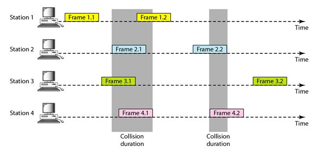 88 |
89 | #### Slotted ALOHA
90 |
91 | - A simple random access protocol where time is divided into time-slots.
92 | - Nodes are allowed to transmit at slot beginnings. Collisions are detected, and nodes retransmit with a probability.
93 | - If a station misses out the allowed time, it must wait for the next slot. This reduces the probability of collisions.
94 | - Efficiency is determined by the long-run fraction of successful slots.
95 |
96 |
88 |
89 | #### Slotted ALOHA
90 |
91 | - A simple random access protocol where time is divided into time-slots.
92 | - Nodes are allowed to transmit at slot beginnings. Collisions are detected, and nodes retransmit with a probability.
93 | - If a station misses out the allowed time, it must wait for the next slot. This reduces the probability of collisions.
94 | - Efficiency is determined by the long-run fraction of successful slots.
95 |
96 | 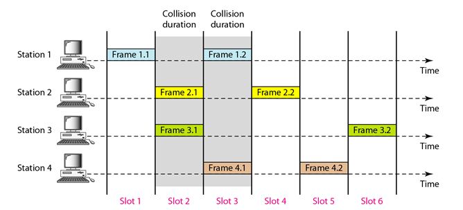 97 |
98 |
99 | #### Carrier Sense Multiple Access (CSMA)
100 |
101 | - CSMA protocols introduce `carrier sensing` to listen before transmitting and `collision detection` to stop transmitting if interference is detected.
102 | - The possibility of collision still exists because of propagation delay
103 | - Types of CSMA:
104 | - 1-Persistent CSMA: If station is busy, it will **CONTINUOUSLY** sense the medium and transmit the data again. [Probability=1]
105 | - Non-persistent CSMA: If station is busy, it will wait for a random time and **RANDOMLY** sense the medium before transmitting again.
106 | - p-Persistent CSMA: It applies to slotted channels; If station is idle, it it will **CONTINUOUSLY** sense and waits for the slotted time to transmits the data [Probability=p]
107 |
108 |
97 |
98 |
99 | #### Carrier Sense Multiple Access (CSMA)
100 |
101 | - CSMA protocols introduce `carrier sensing` to listen before transmitting and `collision detection` to stop transmitting if interference is detected.
102 | - The possibility of collision still exists because of propagation delay
103 | - Types of CSMA:
104 | - 1-Persistent CSMA: If station is busy, it will **CONTINUOUSLY** sense the medium and transmit the data again. [Probability=1]
105 | - Non-persistent CSMA: If station is busy, it will wait for a random time and **RANDOMLY** sense the medium before transmitting again.
106 | - p-Persistent CSMA: It applies to slotted channels; If station is idle, it it will **CONTINUOUSLY** sense and waits for the slotted time to transmits the data [Probability=p]
107 |
108 |  109 |
110 | #### CSMA/CD
111 |
112 | - CSMA/CD is a variant of CSMA that introduces collision detection.
113 | - **Transmission Period**: The time required for a node to transmit a frame.
114 | - **Idle Period**: The time required for a node to wait before transmitting again.
115 | - **Contention Period**: The time required for a node to sense the medium before transmitting again.
116 | - **Binary Exponential Backoff**: It uses binary exponential backoff algorithm to handle collisions.
117 | - Nodes choose a random value from an increasing set for waiting after collisions.
118 | - When a collision is detected, the transmitting nodes immediately stop transmitting and enter a backoff state.
119 |
120 |
121 | #### CSMA/CA
122 |
123 | - Similar to CSMA/CD, CSMA/CA begins with carrier sensing. Nodes listen to the channel to determine if it's busy or idle.
124 | - CSMA/CA introduces virtual carrier sensing to estimate the channel's status.
125 | - CSMA/CA uses a contention window, which is a range of time during which a node may choose to transmit after sensing the channel is idle.
126 | - The size of the contention window may vary, and it influences the probability of a successful transmission.
127 |
128 | ### 6.3.3 Taking Turns Protocols (Controlled Access)
129 |
130 | #### Reservation
131 |
132 | - A station need to make a reservation before sending data.
133 | - In each interval, a reservation frame precedes the data frames sent in that interval.
134 | - If there are N stations in the system, there are exactly N reservation minislots in the reservation frame.
135 | - When a station needs to send a data frame, it makes a reservation in its own minislot.
136 | - The stations that have made reservations can send their data frames after the reservation frame.
137 |
138 |
109 |
110 | #### CSMA/CD
111 |
112 | - CSMA/CD is a variant of CSMA that introduces collision detection.
113 | - **Transmission Period**: The time required for a node to transmit a frame.
114 | - **Idle Period**: The time required for a node to wait before transmitting again.
115 | - **Contention Period**: The time required for a node to sense the medium before transmitting again.
116 | - **Binary Exponential Backoff**: It uses binary exponential backoff algorithm to handle collisions.
117 | - Nodes choose a random value from an increasing set for waiting after collisions.
118 | - When a collision is detected, the transmitting nodes immediately stop transmitting and enter a backoff state.
119 |
120 |
121 | #### CSMA/CA
122 |
123 | - Similar to CSMA/CD, CSMA/CA begins with carrier sensing. Nodes listen to the channel to determine if it's busy or idle.
124 | - CSMA/CA introduces virtual carrier sensing to estimate the channel's status.
125 | - CSMA/CA uses a contention window, which is a range of time during which a node may choose to transmit after sensing the channel is idle.
126 | - The size of the contention window may vary, and it influences the probability of a successful transmission.
127 |
128 | ### 6.3.3 Taking Turns Protocols (Controlled Access)
129 |
130 | #### Reservation
131 |
132 | - A station need to make a reservation before sending data.
133 | - In each interval, a reservation frame precedes the data frames sent in that interval.
134 | - If there are N stations in the system, there are exactly N reservation minislots in the reservation frame.
135 | - When a station needs to send a data frame, it makes a reservation in its own minislot.
136 | - The stations that have made reservations can send their data frames after the reservation frame.
137 |
138 |  139 |
140 | #### Polling
141 |
142 | - The polling protocol requires one of the nodes to be designated as a Master node (Primary station).
143 | - The master node polls each of the nodes in a round-robin fashion.
144 | - The master node can determine when a node has finished sending its frames by observing the lack of a signal on the channel.
145 | - `Functions`: `Poll` (receive) and `Select` (send) functions
146 | - `Drawback`: Polling Delay; If master node fails, channel will be inoperative.
147 |
148 | #### Token Passing
149 |
150 | - The token passing protocol is similar to polling, but it uses a token to determine when a node has finished sending its frames.
151 | - Decentralised and highly efficient; (No Master Node)
152 | - A small, special-purpose frame known as a token is exchanged among the nodes in some fixed order.
153 | - When a node receives a token, it holds onto the token only if it has some frames to transmit; otherwise, it immediately forwards the token to the next node.
154 | - `Examples`: Physical, Dual, Star, and Bus Ring.
155 |
156 | ## 6.4 Link Layer Addressing
157 |
158 | ### 6.4.1 Media Access Control (MAC) Addresses
159 |
160 | - MAC addresses have a flat structure and remain constant for an adapter, analogous to a social security number.
161 | - Typically 6 bytes (48 bits) long (for most LANs) and expressed in hexadecimal notation.
162 | - Originally designed to be permanent, but now changeable via software.
163 | - Managed by IEEE to ensure uniqueness; Companies purchase a chunk of address space (224 addresses) for manufacturing adapters.
164 |
165 | ### 6.4.2 Address Resolution Protocol (ARP)
166 |
167 | - ARP resolves IP addresses to MAC addresses (between Network and Link-Layer Addresses).
168 | - Hosts and routers maintain ARP tables mapping IP addresses to MAC addresses.
169 | - ARP query packet used to obtain MAC address for a given IP address on the same subnet.
170 | - Plug-and-play; ARP tables get built automatically.
171 | - ARP table also contains a time-to-live (TTL) value, which indi- cates when each mapping will be deleted from the table.
172 |
173 |
139 |
140 | #### Polling
141 |
142 | - The polling protocol requires one of the nodes to be designated as a Master node (Primary station).
143 | - The master node polls each of the nodes in a round-robin fashion.
144 | - The master node can determine when a node has finished sending its frames by observing the lack of a signal on the channel.
145 | - `Functions`: `Poll` (receive) and `Select` (send) functions
146 | - `Drawback`: Polling Delay; If master node fails, channel will be inoperative.
147 |
148 | #### Token Passing
149 |
150 | - The token passing protocol is similar to polling, but it uses a token to determine when a node has finished sending its frames.
151 | - Decentralised and highly efficient; (No Master Node)
152 | - A small, special-purpose frame known as a token is exchanged among the nodes in some fixed order.
153 | - When a node receives a token, it holds onto the token only if it has some frames to transmit; otherwise, it immediately forwards the token to the next node.
154 | - `Examples`: Physical, Dual, Star, and Bus Ring.
155 |
156 | ## 6.4 Link Layer Addressing
157 |
158 | ### 6.4.1 Media Access Control (MAC) Addresses
159 |
160 | - MAC addresses have a flat structure and remain constant for an adapter, analogous to a social security number.
161 | - Typically 6 bytes (48 bits) long (for most LANs) and expressed in hexadecimal notation.
162 | - Originally designed to be permanent, but now changeable via software.
163 | - Managed by IEEE to ensure uniqueness; Companies purchase a chunk of address space (224 addresses) for manufacturing adapters.
164 |
165 | ### 6.4.2 Address Resolution Protocol (ARP)
166 |
167 | - ARP resolves IP addresses to MAC addresses (between Network and Link-Layer Addresses).
168 | - Hosts and routers maintain ARP tables mapping IP addresses to MAC addresses.
169 | - ARP query packet used to obtain MAC address for a given IP address on the same subnet.
170 | - Plug-and-play; ARP tables get built automatically.
171 | - ARP table also contains a time-to-live (TTL) value, which indi- cates when each mapping will be deleted from the table.
172 |
173 | 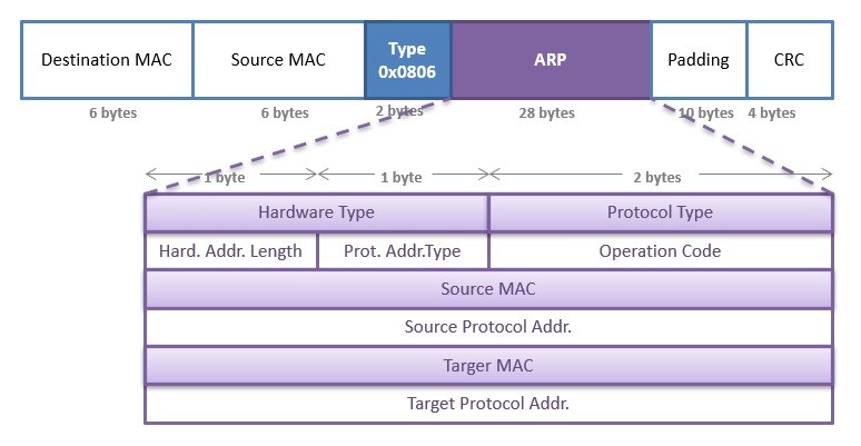 174 |
175 | > A MAC address table, sometimes called a Content Addressable Memory (CAM) table, is used on Ethernet switches to determine where to forward traffic on a LAN.
176 |
177 | | Feature | CAM Table | ARP Table |
178 | |--------------------------|----------------------------------------------|----------------------------------------------|
179 | | **Purpose** | Manages MAC (Media Access Control) addresses | Resolves IP addresses to MAC addresses |
180 | | **Function** | Stores MAC addresses associated with ports | Stores IP addresses and corresponding MAC addresses |
181 | | **Scope** | Limited to the local network or VLAN | Network-wide, may involve broadcast messages |
182 | | **Storage Type** | Typically stored in hardware (CAM) | Stored in software, often in the OS's ARP cache |
183 | | **Security Implications** | Vulnerable to MAC address spoofing | Can be exploited for ARP spoofing attacks |
184 | | **Examples** | Cisco switches, Ethernet switches | Operating systems (Windows, Linux, etc.) |
185 |
186 |
187 |
188 | **Sending a Datagram off the Subnet**
189 |
190 | - When a host on a subnet wants to send a datagram to another subnet, ARP is still used.
191 | - Router interfaces play a crucial role in forwarding the datagram.
192 | - The destination MAC address is the router interface's MAC address, not the final destination's MAC address.
193 | - ARP is used to obtain the MAC address of the first-hop router.
194 | - Router consults a forwarding table to determine the correct interface for forwarding the datagram.
195 | - ARP is used again to obtain the MAC address of the ultimate destination.
196 |
197 |
174 |
175 | > A MAC address table, sometimes called a Content Addressable Memory (CAM) table, is used on Ethernet switches to determine where to forward traffic on a LAN.
176 |
177 | | Feature | CAM Table | ARP Table |
178 | |--------------------------|----------------------------------------------|----------------------------------------------|
179 | | **Purpose** | Manages MAC (Media Access Control) addresses | Resolves IP addresses to MAC addresses |
180 | | **Function** | Stores MAC addresses associated with ports | Stores IP addresses and corresponding MAC addresses |
181 | | **Scope** | Limited to the local network or VLAN | Network-wide, may involve broadcast messages |
182 | | **Storage Type** | Typically stored in hardware (CAM) | Stored in software, often in the OS's ARP cache |
183 | | **Security Implications** | Vulnerable to MAC address spoofing | Can be exploited for ARP spoofing attacks |
184 | | **Examples** | Cisco switches, Ethernet switches | Operating systems (Windows, Linux, etc.) |
185 |
186 |
187 |
188 | **Sending a Datagram off the Subnet**
189 |
190 | - When a host on a subnet wants to send a datagram to another subnet, ARP is still used.
191 | - Router interfaces play a crucial role in forwarding the datagram.
192 | - The destination MAC address is the router interface's MAC address, not the final destination's MAC address.
193 | - ARP is used to obtain the MAC address of the first-hop router.
194 | - Router consults a forwarding table to determine the correct interface for forwarding the datagram.
195 | - ARP is used again to obtain the MAC address of the ultimate destination.
196 |
197 |  198 |
199 | ### 6.4.3 Ethernet Frame Structure
200 |
201 | An Ethernet frame consists of the following components:
202 |
203 | 1. **Data field (46 to 1,500 bytes):** Carries the IP datagram, with a maximum transmission unit (MTU) of 1,500 bytes.
204 | 2. **Destination address (6 bytes):** MAC address of the destination adapter.
205 | 3. **Source address (6 bytes):** MAC address of the transmitting adapter.
206 | 4. **Type field (2 bytes):** Permits multiplexing of network-layer protocols.
207 | 5. **Cyclic redundancy check (CRC) (4 bytes):** Detects bit errors in the frame.
208 | 6. **Preamble (8 bytes):** Synchronizes clocks between adapters.
209 |
210 |
211 | ## 6.5 Link Layer Switches
212 |
213 | - The primary role of a switch is to receive incoming link-layer frames and forward them to outgoing links. Switches employ buffers in output interfaces to handle potential rate mismatches.
214 | - Switches perform two key functions: `filtering` and `forwarding`.
215 | - Filtering determines whether a frame should be dropped or forwarded, while forwarding identifies the interfaces to which a frame should be directed.
216 | - This is achieved through a switch table, containing MAC addresses, associated interfaces, and entry timestamps. Unlike routers, switches forward based on MAC addresses, not IP addresses.
217 |
218 | When a frame arrives:
219 | - If no entry exists for the destination address, the switch broadcasts the frame.
220 | - If there's an entry for the destination on the same interface, the frame is discarded.
221 | - If there's an entry for a different interface, the frame is forwarded to that interface.
222 |
223 | **Advantages of Switches**
224 | - `Elimination of Collisions`: Switches prevent collisions, maximizing bandwidth.
225 | - `Heterogeneous Links`: Different LAN links can operate at varying speeds and media types.
226 | - `Management`: Switches offer enhanced security and ease of network management.
227 |
228 | **Self-Learning Capability**
229 |
230 | Switches possess the self-learning property, automatically building and updating their switch tables without manual intervention. The process involves recording MAC addresses, associated interfaces, and timestamps for each incoming frame. Entries are removed after a specified aging time, ensuring the switch table remains accurate.
231 |
232 | ## 6.6 Virtual Local Area Networks (VLANs)
233 |
234 | - Hosts within a VLAN communicate as if connected directly to the switch, creating broadcast domains within each VLAN.
235 | - VLANs effectively isolate traffic, optimize switch utilization, and simplify user management.
236 |
237 | In a port-based VLAN,
238 | - Switch ports are grouped into VLANs by the network manager.
239 | - Each VLAN forms a broadcast domain, isolating broadcast traffic within the VLAN.
240 |
241 | **VLAN Switch Configuration**
242 |
243 | - The network manager configures port-to-VLAN mappings using switch management software.
244 | - Switch hardware delivers frames only between ports belonging to the same VLAN.
245 | - However, this introduces a challenge: How can traffic from one VLAN be sent to another?
246 |
247 | **VLAN Trunking**
248 |
249 | - To address inter-VLAN communication, VLAN trunking was introduced. A trunk port on each switch, configured to belong to all VLANs, facilitates VLAN interconnection. Trunk links forward frames between switches, ensuring effective communication.
250 |
251 | - The IEEE standard 802.1Q defines VLAN trunking. A special Ethernet frame format includes a four-byte VLAN tag in the header, carrying the VLAN identity. The VLAN tag contains a Tag Protocol Identifier (TPID) field, Tag Control Information field with a VLAN identifier, and a priority field.
252 |
253 |
198 |
199 | ### 6.4.3 Ethernet Frame Structure
200 |
201 | An Ethernet frame consists of the following components:
202 |
203 | 1. **Data field (46 to 1,500 bytes):** Carries the IP datagram, with a maximum transmission unit (MTU) of 1,500 bytes.
204 | 2. **Destination address (6 bytes):** MAC address of the destination adapter.
205 | 3. **Source address (6 bytes):** MAC address of the transmitting adapter.
206 | 4. **Type field (2 bytes):** Permits multiplexing of network-layer protocols.
207 | 5. **Cyclic redundancy check (CRC) (4 bytes):** Detects bit errors in the frame.
208 | 6. **Preamble (8 bytes):** Synchronizes clocks between adapters.
209 |
210 |
211 | ## 6.5 Link Layer Switches
212 |
213 | - The primary role of a switch is to receive incoming link-layer frames and forward them to outgoing links. Switches employ buffers in output interfaces to handle potential rate mismatches.
214 | - Switches perform two key functions: `filtering` and `forwarding`.
215 | - Filtering determines whether a frame should be dropped or forwarded, while forwarding identifies the interfaces to which a frame should be directed.
216 | - This is achieved through a switch table, containing MAC addresses, associated interfaces, and entry timestamps. Unlike routers, switches forward based on MAC addresses, not IP addresses.
217 |
218 | When a frame arrives:
219 | - If no entry exists for the destination address, the switch broadcasts the frame.
220 | - If there's an entry for the destination on the same interface, the frame is discarded.
221 | - If there's an entry for a different interface, the frame is forwarded to that interface.
222 |
223 | **Advantages of Switches**
224 | - `Elimination of Collisions`: Switches prevent collisions, maximizing bandwidth.
225 | - `Heterogeneous Links`: Different LAN links can operate at varying speeds and media types.
226 | - `Management`: Switches offer enhanced security and ease of network management.
227 |
228 | **Self-Learning Capability**
229 |
230 | Switches possess the self-learning property, automatically building and updating their switch tables without manual intervention. The process involves recording MAC addresses, associated interfaces, and timestamps for each incoming frame. Entries are removed after a specified aging time, ensuring the switch table remains accurate.
231 |
232 | ## 6.6 Virtual Local Area Networks (VLANs)
233 |
234 | - Hosts within a VLAN communicate as if connected directly to the switch, creating broadcast domains within each VLAN.
235 | - VLANs effectively isolate traffic, optimize switch utilization, and simplify user management.
236 |
237 | In a port-based VLAN,
238 | - Switch ports are grouped into VLANs by the network manager.
239 | - Each VLAN forms a broadcast domain, isolating broadcast traffic within the VLAN.
240 |
241 | **VLAN Switch Configuration**
242 |
243 | - The network manager configures port-to-VLAN mappings using switch management software.
244 | - Switch hardware delivers frames only between ports belonging to the same VLAN.
245 | - However, this introduces a challenge: How can traffic from one VLAN be sent to another?
246 |
247 | **VLAN Trunking**
248 |
249 | - To address inter-VLAN communication, VLAN trunking was introduced. A trunk port on each switch, configured to belong to all VLANs, facilitates VLAN interconnection. Trunk links forward frames between switches, ensuring effective communication.
250 |
251 | - The IEEE standard 802.1Q defines VLAN trunking. A special Ethernet frame format includes a four-byte VLAN tag in the header, carrying the VLAN identity. The VLAN tag contains a Tag Protocol Identifier (TPID) field, Tag Control Information field with a VLAN identifier, and a priority field.
252 |
253 |  254 |
255 | ## 6.7 Multiprotocol Label Switching (MPLS)
256 |
257 | MPLS enhances IP router's forwarding speed by incorporating a key concept from virtual-circuit networks: `fixed-length labels`. Unlike circuit-switched networks, MPLS is a packet-switched, virtual-circuit network, co-existing with IP infrastructure.
258 |
259 | - An MPLS-capable router adds a small MPLS header to a link-layer frame between MPLS-capable devices. This header includes fields like the `label`, `experimental bits`, an S bit indicating the end of a stacked header series, and a `time-to-live` field.
260 | - MPLS-capable routers, known as `label-switched` routers, forward MPLS frames by looking up labels in their forwarding tables, eliminating the need to extract IP addresses for routing decisions.
261 | - MPLS labels and their associations with IP destinations are distributed among MPLS-capable routers.
262 | - MPLS introduces traffic engineering capabilities, allowing routers to forward packets along paths not determined by standard IP routing protocols. This enables network operators to override normal IP routing for specific traffic management purposes.
263 | - MPLS can be utilized for fast restoration of forwarding paths, implementing virtual private networks (VPNs), and various other purposes.
264 |
265 |
254 |
255 | ## 6.7 Multiprotocol Label Switching (MPLS)
256 |
257 | MPLS enhances IP router's forwarding speed by incorporating a key concept from virtual-circuit networks: `fixed-length labels`. Unlike circuit-switched networks, MPLS is a packet-switched, virtual-circuit network, co-existing with IP infrastructure.
258 |
259 | - An MPLS-capable router adds a small MPLS header to a link-layer frame between MPLS-capable devices. This header includes fields like the `label`, `experimental bits`, an S bit indicating the end of a stacked header series, and a `time-to-live` field.
260 | - MPLS-capable routers, known as `label-switched` routers, forward MPLS frames by looking up labels in their forwarding tables, eliminating the need to extract IP addresses for routing decisions.
261 | - MPLS labels and their associations with IP destinations are distributed among MPLS-capable routers.
262 | - MPLS introduces traffic engineering capabilities, allowing routers to forward packets along paths not determined by standard IP routing protocols. This enables network operators to override normal IP routing for specific traffic management purposes.
263 | - MPLS can be utilized for fast restoration of forwarding paths, implementing virtual private networks (VPNs), and various other purposes.
264 |
265 |  266 |
--------------------------------------------------------------------------------
/README.md:
--------------------------------------------------------------------------------
1 | # ✍🏼 Notes: Computer Networking: A Top-down Approach
2 |
3 | This repository includes notes for "Computer Networking: A Top-down Approach," 8th Edition by James F. Kurose and Keith W. Ross, created for the course ENPM694: Networks and Protocols-Fall 2023 at the University of Maryland, College Park.
4 |
5 | 
6 |
7 |
266 |
--------------------------------------------------------------------------------
/README.md:
--------------------------------------------------------------------------------
1 | # ✍🏼 Notes: Computer Networking: A Top-down Approach
2 |
3 | This repository includes notes for "Computer Networking: A Top-down Approach," 8th Edition by James F. Kurose and Keith W. Ross, created for the course ENPM694: Networks and Protocols-Fall 2023 at the University of Maryland, College Park.
4 |
5 | 
6 |
7 |
8 |
48 |
49 |
50 | Chapter 1: Computer Networking and the Internet
9 | 10 | 11 | - [1.1 A Nuts-and-Bolts Description (Infrastructure based Internet)](https://github.com/VasanthVanan/computer-networking-top-down-approach-notes/blob/main/Chapter%201:%20Computer%20Networks%20and%20the%20Internet.md#11-a-nuts-and-bolts-description-infrastructure-based-internet) 12 | 13 | - [1.2 A Services Description (Service based Internet)](https://github.com/VasanthVanan/computer-networking-top-down-approach-notes/blob/main/Chapter%201:%20Computer%20Networks%20and%20the%20Internet.md#12-a-services-description-service-based-internet) 14 | 15 | - [1.3 The Network Edge](https://github.com/VasanthVanan/computer-networking-top-down-approach-notes/blob/main/Chapter%201:%20Computer%20Networks%20and%20the%20Internet.md#13-the-network-edge) 16 | 17 | - [1.4 Access Networks](https://github.com/VasanthVanan/computer-networking-top-down-approach-notes/blob/main/Chapter%201:%20Computer%20Networks%20and%20the%20Internet.md#14-access-networks) 18 | 19 | - [1.4.1 Home Access: DSL](https://github.com/VasanthVanan/computer-networking-top-down-approach-notes/blob/main/Chapter%201:%20Computer%20Networks%20and%20the%20Internet.md#141-home-access-dsl) 20 | 21 | - [1.4.2 Home Access: Cable](https://github.com/VasanthVanan/computer-networking-top-down-approach-notes/blob/main/Chapter%201:%20Computer%20Networks%20and%20the%20Internet.md#142-home-access-cable) 22 | 23 | - [1.4.3 Home Access: FTTH](https://github.com/VasanthVanan/computer-networking-top-down-approach-notes/blob/main/Chapter%201:%20Computer%20Networks%20and%20the%20Internet.md#143-home-access-ftth) 24 | 25 | - [1.4.4 Home Access: 5G Fixed Wireless](https://github.com/VasanthVanan/computer-networking-top-down-approach-notes/blob/main/Chapter%201:%20Computer%20Networks%20and%20the%20Internet.md#144-home-access-5g-fixed-wireless) 26 | 27 | - [1.4.5 Enterprise & Home Access: Ethernet, WiFi](https://github.com/VasanthVanan/computer-networking-top-down-approach-notes/blob/main/Chapter%201:%20Computer%20Networks%20and%20the%20Internet.md#145-enterprise--home-access-ethernet-wifi) 28 | 29 | - [1.5 Physical Media](https://github.com/VasanthVanan/computer-networking-top-down-approach-notes/blob/main/Chapter%201:%20Computer%20Networks%20and%20the%20Internet.md#15-physical-media) 30 | 31 | - [1.6 Packet Switching (Store-and-Forward Transmission)](https://github.com/VasanthVanan/computer-networking-top-down-approach-notes/blob/main/Chapter%201:%20Computer%20Networks%20and%20the%20Internet.md#16-packet-switching-store-and-forward-transmission) 32 | 33 | - [1.7 Circuit Switching](https://github.com/VasanthVanan/computer-networking-top-down-approach-notes/blob/main/Chapter%201:%20Computer%20Networks%20and%20the%20Internet.md#17-circuit-switching) 34 | 35 | - [1.8 Networks of Networks](https://github.com/VasanthVanan/computer-networking-top-down-approach-notes/blob/main/Chapter%201:%20Computer%20Networks%20and%20the%20Internet.md#18-networks-of-networks) 36 | 37 | - [1.9 Delay, Loss, Throughput](https://github.com/VasanthVanan/computer-networking-top-down-approach-notes/blob/main/Chapter%201:%20Computer%20Networks%20and%20the%20Internet.md#19-delay-loss-throughput) 38 | 39 | - [1.10 Throughput](https://github.com/VasanthVanan/computer-networking-top-down-approach-notes/blob/main/Chapter%201:%20Computer%20Networks%20and%20the%20Internet.md#110-throughput) 40 | 41 | - [1.11 Protocol Layers](https://github.com/VasanthVanan/computer-networking-top-down-approach-notes/blob/main/Chapter%201:%20Computer%20Networks%20and%20the%20Internet.md#111-protocol-layers) 42 | 43 | - [1.12 Networks Under Attack](https://github.com/VasanthVanan/computer-networking-top-down-approach-notes/blob/main/Chapter%201:%20Computer%20Networks%20and%20the%20Internet.md#112-networks-under-attack) 44 | 45 |  46 | 47 |
51 |
95 |
96 |
97 | Chapter 2: Aplication Layer
52 | 53 | 54 | * [2.1 Principle of Network Applications](https://github.com/VasanthVanan/computer-networking-top-down-approach-notes/blob/main/Chapter%202:%20Application%20Layer.md#21-principle-of-network-applications) 55 | 56 | * [2.2 Transport Services (TCP & UDP)](https://github.com/VasanthVanan/computer-networking-top-down-approach-notes/blob/main/Chapter%202:%20Application%20Layer.md#22-transport-services-tcp--udp) 57 | 58 | * [2.3 Application Layer Protocol: Web and HTTP](https://github.com/VasanthVanan/computer-networking-top-down-approach-notes/blob/main/Chapter%202:%20Application%20Layer.md#23-application-layer-protocol-web-and-http) 59 | 60 | * [2.3.1 Non-Persistent and Persistent Connections](https://github.com/VasanthVanan/computer-networking-top-down-approach-notes/blob/main/Chapter%202:%20Application%20Layer.md#231-non-persistent-and-persistent-connections) 61 | 62 | * [2.3.2 HTTP Message Format](https://github.com/VasanthVanan/computer-networking-top-down-approach-notes/blob/main/Chapter%202:%20Application%20Layer.md#232-http-message-format) 63 | 64 | * [2.3.3 Cookies](https://github.com/VasanthVanan/computer-networking-top-down-approach-notes/blob/main/Chapter%202:%20Application%20Layer.md#233-cookies) 65 | 66 | * [2.3.4 Web Caching](https://github.com/VasanthVanan/computer-networking-top-down-approach-notes/blob/main/Chapter%202:%20Application%20Layer.md#234-web-caching) 67 | 68 | * [2.3.4 HTTP/2](https://github.com/VasanthVanan/computer-networking-top-down-approach-notes/blob/main/Chapter%202:%20Application%20Layer.md#235-http2) 69 | 70 | * [2.4 Application Layer Protocol: SMTP](https://github.com/VasanthVanan/computer-networking-top-down-approach-notes/blob/main/Chapter%202:%20Application%20Layer.md#24-application-layer-protocol-smtp) 71 | 72 | * [2.4.1 Email Components](https://github.com/VasanthVanan/computer-networking-top-down-approach-notes/blob/main/Chapter%202:%20Application%20Layer.md#241-email-components) 73 | 74 | * [2.4.2 SMTP Basics](https://github.com/VasanthVanan/computer-networking-top-down-approach-notes/blob/main/Chapter%202:%20Application%20Layer.md#242-smtp-basics) 75 | 76 | * [2.4.3 Mail Message Structure](https://github.com/VasanthVanan/computer-networking-top-down-approach-notes/blob/main/Chapter%202:%20Application%20Layer.md#243-mail-message-structure) 77 | 78 | * [2.4.4 Mail Access Protocols](https://github.com/VasanthVanan/computer-networking-top-down-approach-notes/blob/main/Chapter%202:%20Application%20Layer.md#244-mail-access-protocols) 79 | 80 | * [2.5 Application Layer Protocol: DNS](https://github.com/VasanthVanan/computer-networking-top-down-approach-notes/blob/main/Chapter%202:%20Application%20Layer.md#25-application-layer-protocol-dns) 81 | 82 | * [2.5.1 How DNS Works: High-Level Overview](https://github.com/VasanthVanan/computer-networking-top-down-approach-notes/blob/main/Chapter%202:%20Application%20Layer.md#251-how-dns-works-high-level-overview) 83 | 84 | * [2.5.2 Distributed, Hierarchical Database](https://github.com/VasanthVanan/computer-networking-top-down-approach-notes/blob/main/Chapter%202:%20Application%20Layer.md#252-distributed-hierarchical-database) 85 | 86 | * [2.5.3 Recursive vs Iterative DNS Queries](https://github.com/VasanthVanan/computer-networking-top-down-approach-notes/blob/main/Chapter%202:%20Application%20Layer.md#253-recursive-vs-iterative-dns-queries) 87 | 88 | * [2.5.4 DNS Records & Messages](https://github.com/VasanthVanan/computer-networking-top-down-approach-notes/blob/main/Chapter%202:%20Application%20Layer.md#254-dns-records--messages) 89 | 90 | * [2.5.5 Inserting Records to DNS Database](https://github.com/VasanthVanan/computer-networking-top-down-approach-notes/blob/main/Chapter%202:%20Application%20Layer.md#255-inserting-records-to-dns-database) 91 | 92 |  93 | 94 |
98 |
152 |
153 |
154 | Chapter 3: Transport Layer
99 | 100 | 101 | * [3.1 Transport-Layer Services](https://github.com/VasanthVanan/computer-networking-top-down-approach-notes/blob/main/Chapter%203:%20Transport%20Layer.md#31-transport-layer-services) 102 | 103 | * [3.2 Multiplexing and Demultiplexing](https://github.com/VasanthVanan/computer-networking-top-down-approach-notes/blob/main/Chapter%203:%20Transport%20Layer.md#32-multiplexing-and-demultiplexing) 104 | 105 | * [3.3 Connectionless Multiplexing and Demultiplexing](https://github.com/VasanthVanan/computer-networking-top-down-approach-notes/blob/main/Chapter%203:%20Transport%20Layer.md#33-connectionless-multiplexing-and-demultiplexing) 106 | 107 | * [3.4 Connection-Oriented Multiplexing and Demultiplexing](https://github.com/VasanthVanan/computer-networking-top-down-approach-notes/blob/main/Chapter%203:%20Transport%20Layer.md#34-connection-oriented-multiplexing-and-demultiplexing) 108 | 109 | * [3.5 UDP (User Datagram Protocol)](https://github.com/VasanthVanan/computer-networking-top-down-approach-notes/blob/main/Chapter%203:%20Transport%20Layer.md#35-udp-user-datagram-protocol) 110 | 111 | * [3.6 Building Reliable Data Transfer Protocol](https://github.com/VasanthVanan/computer-networking-top-down-approach-notes/blob/main/Chapter%203:%20Transport%20Layer.md#36-building-reliable-data-transfer-portocol) 112 | 113 | * [3.6.1 RDT 1.0](https://github.com/VasanthVanan/computer-networking-top-down-approach-notes/blob/main/Chapter%203:%20Transport%20Layer.md#361-rdt-10) 114 | 115 | * [3.6.2 RDT 2.0](https://github.com/VasanthVanan/computer-networking-top-down-approach-notes/blob/main/Chapter%203:%20Transport%20Layer.md#362-rdt-20) 116 | 117 | * [3.6.3 RDT 2.1](https://github.com/VasanthVanan/computer-networking-top-down-approach-notes/blob/main/Chapter%203:%20Transport%20Layer.md#363-rdt-21) 118 | 119 | * [3.6.4 RDT 3.0](https://github.com/VasanthVanan/computer-networking-top-down-approach-notes/blob/main/Chapter%203:%20Transport%20Layer.md#364-rdt-30) 120 | 121 | * [3.6.5 Go-Back-N (GBN)](https://github.com/VasanthVanan/computer-networking-top-down-approach-notes/blob/main/Chapter%203:%20Transport%20Layer.md#365-go-back-n-gbn) 122 | 123 | * [3.6.6 Selective Repeat (SR)](https://github.com/VasanthVanan/computer-networking-top-down-approach-notes/blob/main/Chapter%203:%20Transport%20Layer.md#366-selective-repeat-sr) 124 | 125 | * [3.6.7 Improvements in RDT Protocols](https://github.com/VasanthVanan/computer-networking-top-down-approach-notes/blob/main/Chapter%203:%20Transport%20Layer.md#367-improvements-in-rdt-protocols) 126 | 127 | * [3.7 TCP (Transmission Control Protocol)](https://github.com/VasanthVanan/computer-networking-top-down-approach-notes/blob/main/Chapter%203:%20Transport%20Layer.md#37-tcp-transmission-control-protocol) 128 | 129 | * [3.7.1 Round-Trip Time Estimation and Timeout in TCP](https://github.com/VasanthVanan/computer-networking-top-down-approach-notes/blob/main/Chapter%203:%20Transport%20Layer.md#371-round-trip-time-estimation-and-timeout-in-tcp) 130 | 131 | * [3.7.2 Reliable Data Transfer](https://github.com/VasanthVanan/computer-networking-top-down-approach-notes/blob/main/Chapter%203:%20Transport%20Layer.md#372-reliable-data-transfer) 132 | 133 | * [3.7.3 Flow Control](https://github.com/VasanthVanan/computer-networking-top-down-approach-notes/blob/main/Chapter%203:%20Transport%20Layer.md#373-flow-control) 134 | 135 | * [3.7.4 TCP Connection Management](https://github.com/VasanthVanan/computer-networking-top-down-approach-notes/blob/main/Chapter%203:%20Transport%20Layer.md#374-tcp-connection-management) 136 | 137 | * [3.8 Congestion Control](https://github.com/VasanthVanan/computer-networking-top-down-approach-notes/blob/main/Chapter%203:%20Transport%20Layer.md#38-congestion-control) 138 | 139 | * [3.8.1 Classic TCP Congestion Control](https://github.com/VasanthVanan/computer-networking-top-down-approach-notes/blob/main/Chapter%203:%20Transport%20Layer.md#381-classic-tcp-congestion-control) 140 | 141 | * [3.9 Network Assisted Congestions](https://github.com/VasanthVanan/computer-networking-top-down-approach-notes/blob/main/Chapter%203:%20Transport%20Layer.md#39-network-assisted-congestions) 142 | 143 | * [3.9.1 Explicit Congestion Notification](https://github.com/VasanthVanan/computer-networking-top-down-approach-notes/blob/main/Chapter%203:%20Transport%20Layer.md#391-explicit-congestion-notification) 144 | 145 | * [3.9.2 Delay based Congestion Control](https://github.com/VasanthVanan/computer-networking-top-down-approach-notes/blob/main/Chapter%203:%20Transport%20Layer.md#392-delay-based-congestion-control) 146 | 147 | * [3.10 Evolution of Transport Layer Functionality](https://github.com/VasanthVanan/computer-networking-top-down-approach-notes/blob/main/Chapter%203:%20Transport%20Layer.md#310-evolution-of-transport-layer-functionality) 148 | 149 |  150 | 151 |
155 |
185 |
186 | Chapter 4: Network Layer (Data Plane)
156 | 157 | 158 | * [4.1 Overview](https://github.com/VasanthVanan/computer-networking-top-down-approach-notes/blob/main/Chapter%204:%20Network%20Layer%20(Data%20Plane).md#41-overview) 159 | 160 | * [4.2 Router Architecture](https://github.com/VasanthVanan/computer-networking-top-down-approach-notes/blob/main/Chapter%204:%20Network%20Layer%20(Data%20Plane).md#42-router-architecture) 161 | 162 | * [4.2.1 Input Port Processing and Destination-Based Forwarding](https://github.com/VasanthVanan/computer-networking-top-down-approach-notes/blob/main/Chapter%204:%20Network%20Layer%20(Data%20Plane).md#421-input-port-processing-and-destination-based-forwarding) 163 | 164 | * [4.2.2 Switching Fabric in Router Architecture](https://github.com/VasanthVanan/computer-networking-top-down-approach-notes/blob/main/Chapter%204%3A%20Network%20Layer%20(Data%20Plane).md#422-switching-fabric-in-router-architecture) 165 | 166 | * [4.2.3 Output Port Processing](https://github.com/VasanthVanan/computer-networking-top-down-approach-notes/blob/main/Chapter%204%3A%20Network%20Layer%20(Data%20Plane).md#423-output-port-processing) 167 | 168 | * [4.2.4 Packet Scheduling](https://github.com/VasanthVanan/computer-networking-top-down-approach-notes/blob/main/Chapter%204%3A%20Network%20Layer%20(Data%20Plane).md#424-packet-scheduling) 169 | 170 | * [4.3. IP Addressing](https://github.com/VasanthVanan/computer-networking-top-down-approach-notes/blob/main/Chapter%204%3A%20Network%20Layer%20(Data%20Plane).md#43-ip-addressing) 171 | 172 | * [4.3.1 IPv4](https://github.com/VasanthVanan/computer-networking-top-down-approach-notes/blob/main/Chapter%204%3A%20Network%20Layer%20(Data%20Plane).md#431-ipv4) 173 | 174 | * [4.3.2 CIDR (Classless Interdomain Routing)](https://github.com/VasanthVanan/computer-networking-top-down-approach-notes/blob/main/Chapter%204%3A%20Network%20Layer%20(Data%20Plane).md#432-cidr-classless-interdomain-routing) 175 | 176 | * [4.3.3 Dynamic Host Configuration Protocol (DHCP)](https://github.com/VasanthVanan/computer-networking-top-down-approach-notes/blob/main/Chapter%204%3A%20Network%20Layer%20(Data%20Plane).md#433-dynamic-host-configuration-protocol-dhcp) 177 | 178 | * [4.3.4 Network Address Translation (NAT)](https://github.com/VasanthVanan/computer-networking-top-down-approach-notes/blob/main/Chapter%204%3A%20Network%20Layer%20(Data%20Plane).md#434-network-address-translation-nat) 179 | 180 | * [4.3.5 IPv6](https://github.com/VasanthVanan/computer-networking-top-down-approach-notes/blob/main/Chapter%204%3A%20Network%20Layer%20(Data%20Plane).md#435-ipv6) 181 | 182 |  183 | 184 |
187 |
218 |
219 | Chapter 5: Network Layer (Control Plane)
188 | 189 | * [5.1 Routing Algorithms](https://github.com/VasanthVanan/computer-networking-top-down-approach-notes/blob/main/Chapter%205%3A%20Network%20Layer%20(Control%20Plane).md#51-routing-algorithms) 190 | 191 | * [5.2 Intra-AS Routing: OSPF](https://github.com/VasanthVanan/computer-networking-top-down-approach-notes/blob/main/Chapter%205%3A%20Network%20Layer%20(Control%20Plane).md#52-intra-as-routing-ospf) 192 | 193 | * [5.2.1 OSPF (Open Shortest Path First)](https://github.com/VasanthVanan/computer-networking-top-down-approach-notes/blob/main/Chapter%205%3A%20Network%20Layer%20(Control%20Plane).md#521-ospf-open-shortest-path-first) 194 | 195 | * [5.2.2 OSPF Features and Advancements](https://github.com/VasanthVanan/computer-networking-top-down-approach-notes/blob/main/Chapter%205%3A%20Network%20Layer%20(Control%20Plane).md#522-ospf-features-and-advancements) 196 | 197 | * [5.3 Inter-AS Routing: BGP](https://github.com/VasanthVanan/computer-networking-top-down-approach-notes/blob/main/Chapter%205%3A%20Network%20Layer%20(Control%20Plane).md#53-inter-as-routing-bgp) 198 | 199 | * [5.3.1 BGP Responsibilities](https://github.com/VasanthVanan/computer-networking-top-down-approach-notes/blob/main/Chapter%205%3A%20Network%20Layer%20(Control%20Plane).md#531-bgp-responsibilities) 200 | 201 | * [5.3.2 Hot Potato Routing in BGP](https://github.com/VasanthVanan/computer-networking-top-down-approach-notes/blob/main/Chapter%205%3A%20Network%20Layer%20(Control%20Plane).md#532-hot-potato-routing-in-bgp) 202 | 203 | * [5.3.3 IP Anycast in BGP](https://github.com/VasanthVanan/computer-networking-top-down-approach-notes/blob/main/Chapter%205%3A%20Network%20Layer%20(Control%20Plane).md#533-ip-anycast-in-bgp) 204 | 205 | * [5.4 ICMP (Internet Control Message Protocol)](https://github.com/VasanthVanan/computer-networking-top-down-approach-notes/blob/main/Chapter%205%3A%20Network%20Layer%20(Control%20Plane).md#54-icmp-internet-control-message-protocol) 206 | 207 | * [5.5 Network Management](https://github.com/VasanthVanan/computer-networking-top-down-approach-notes/blob/main/Chapter%205%3A%20Network%20Layer%20(Control%20Plane).md#55-network-management) 208 | 209 | * [5.5.1 Network Management Components](https://github.com/VasanthVanan/computer-networking-top-down-approach-notes/blob/main/Chapter%205%3A%20Network%20Layer%20(Control%20Plane).md#551-network-management-components) 210 | 211 | * [5.5.2 SNMPv3 Message Types](https://github.com/VasanthVanan/computer-networking-top-down-approach-notes/blob/main/Chapter%205%3A%20Network%20Layer%20(Control%20Plane).md#552-snmpv3-message-types) 212 | 213 | * [5.5.3 NETCONF/YANG](https://github.com/VasanthVanan/computer-networking-top-down-approach-notes/blob/main/Chapter%205%3A%20Network%20Layer%20(Control%20Plane).md#553-netconfyang) 214 | 215 |  216 | 217 |
220 |
250 |
251 |
--------------------------------------------------------------------------------