├── doc
├── AD5940.pdf
├── SensorPal Startup Rev 0.1.pdf
├── EVAL-AD5940-UG-1292_(Rev. 0).pdf
├── Application Notes
│ ├── AN-1557_Rev0.pdf
│ └── AN-1563_Rev0.pdf
└── Schematics
│ └── AD5940
│ ├── AD5940 Z Test .pdf
│ ├── EVAL-AD5940BIOZ.pdf
│ ├── EVAL-AD5940ELCZ.pdf
│ ├── Layout
│ ├── AD5940 Z Test.pdf
│ └── EVAL-AD5940BIOZ.pdf
│ └── Footprint BXL
│ ├── AD5940BCBZ.pdf
│ └── AD5940BCBZ-RL.bxl
├── .gitmodules
├── examples
├── AD5940_Impedance_Adjustable_with_frequency
│ ├── ADICUP3029
│ │ ├── .project
│ │ ├── AD5940_Impedance_Adjustable_with_frequency.rteconfig
│ │ └── AD5940_Impedance.rteconfig
│ ├── Impedance.h
│ └── AD5940Main.c
├── AD5940_LPLoop
│ ├── ADICUP3029
│ │ └── AD5940_LPLoop.rteconfig
│ └── AD5940_LpLoop.c
├── AD5940_Reset
│ ├── main.c
│ ├── ADICUP3029
│ │ └── AD5940_Reset.rteconfig
│ └── AD5940_Reset.c
├── AD5940_WG
│ ├── ADICUP3029
│ │ ├── AD5940_WG.rteconfig
│ │ └── main.c
│ ├── AD5940_WGSin.c
│ ├── AD5940_WGTrapezoid.c
│ └── AD5940_WGSin_LPDAC.c
├── AD5940_DFT
│ ├── ADICUP3029
│ │ ├── AD5940_DFT.rteconfig
│ │ └── main.c
│ └── AD5940_DFTPolling.c
├── AD5940_ECG
│ ├── ADICUP3029
│ │ ├── AD5940_ECG.rteconfig
│ │ └── main.c
│ ├── Electrocardiograph.h
│ └── AD5940Main.c
├── AD5940_EDA
│ ├── ADICUP3029
│ │ └── AD5940_EDA.rteconfig
│ └── NUCLEO-F411
│ │ └── main.c
├── AD5940_LPDAC
│ ├── ADICUP3029
│ │ └── AD5940_LPDAC.rteconfig
│ └── AD5940_LPDAC.c
├── AD5940_Ramp
│ ├── ADICUP3029
│ │ └── AD5940_Ramp.rteconfig
│ └── RampTest.h
├── AD5940_SPI
│ ├── ADICUP3029
│ │ └── AD5940_SPI.rteconfig
│ └── AD5940_SPI.c
├── AD5940_BioElec
│ ├── ADICUP3029
│ │ └── AD5940_BioElec.rteconfig
│ └── Electrocardiograph.h
├── AD5940_BIOZ-2Wire
│ ├── ADICUP3029
│ │ └── AD5940_BIOZ-2Wire.rteconfig
│ └── BIOZ-2Wire.h
├── AD5940_ECSns_EIS
│ ├── ADICUP3029
│ │ └── AD5940_ECSensEIS.rteconfig
│ └── Impedance.h
├── AD5940_HSDACCal
│ ├── ADICUP3029
│ │ └── AD5940_HSDACCal.rteconfig
│ └── AD5940_HSDACCal.c
├── AD5940_Impedance
│ ├── ADICUP3029
│ │ └── AD5940_Impedance.rteconfig
│ ├── Impedance.h
│ └── AD5940Main.c
├── AD5940_Sequencer
│ └── ADICUP3029
│ │ └── AD5940_Sequencer.rteconfig
├── AD5940_Amperometric
│ ├── ADICUP3029
│ │ └── AD5940_Amperometric.rteconfig
│ └── Amperometric.h
├── AD5940_Temperature
│ └── ADICUP3029
│ │ └── AD5940_Temperature.rteconfig
├── AD5940_SqrWaveVoltammetry
│ ├── ADICUP3029
│ │ └── AD5940_SqrWaveVoltmmetry.rteconfig
│ └── SqrWaveVoltammetry.h
├── AD5940_ChronoAmperometric
│ └── ADICUP3029
│ │ └── AD5940_ChronoAmperometric.rteconfig
├── AD5940_BATImpedance
│ ├── ADICUP3029
│ │ ├── AD5940_BATImpedance.rteconfig
│ │ └── main.c
│ └── BATImpedance.h
├── AD5940_ADC
│ ├── ADICUP3029
│ │ ├── AD5940_ADC.rteconfig
│ │ └── main.c
│ ├── AD5940_ADCPolling.c
│ └── AD5940_ADCMeanFIFO.c
├── AD5940_BIA_HiZ_Electrodes
│ └── ADICUP3029
│ │ └── AD5940_BIA_HiZ_Electrodes.rteconfig
├── ADICUP3029.eww
├── ADICUP3029.uvmpw
├── NUCLEO-F411RE.uvmpw
└── AD5940_BIA
│ └── ADICUP3029
│ └── main.c
├── .gitignore
└── README.md
/doc/AD5940.pdf:
--------------------------------------------------------------------------------
https://raw.githubusercontent.com/analogdevicesinc/ad5940-examples/HEAD/doc/AD5940.pdf
--------------------------------------------------------------------------------
/.gitmodules:
--------------------------------------------------------------------------------
1 | [submodule "examples/ad5940lib"]
2 | path = examples/ad5940lib
3 | url = https://github.com/analogdevicesinc/ad5940lib
4 |
--------------------------------------------------------------------------------
/doc/SensorPal Startup Rev 0.1.pdf:
--------------------------------------------------------------------------------
https://raw.githubusercontent.com/analogdevicesinc/ad5940-examples/HEAD/doc/SensorPal Startup Rev 0.1.pdf
--------------------------------------------------------------------------------
/doc/EVAL-AD5940-UG-1292_(Rev. 0).pdf:
--------------------------------------------------------------------------------
https://raw.githubusercontent.com/analogdevicesinc/ad5940-examples/HEAD/doc/EVAL-AD5940-UG-1292_(Rev. 0).pdf
--------------------------------------------------------------------------------
/doc/Application Notes/AN-1557_Rev0.pdf:
--------------------------------------------------------------------------------
https://raw.githubusercontent.com/analogdevicesinc/ad5940-examples/HEAD/doc/Application Notes/AN-1557_Rev0.pdf
--------------------------------------------------------------------------------
/doc/Application Notes/AN-1563_Rev0.pdf:
--------------------------------------------------------------------------------
https://raw.githubusercontent.com/analogdevicesinc/ad5940-examples/HEAD/doc/Application Notes/AN-1563_Rev0.pdf
--------------------------------------------------------------------------------
/doc/Schematics/AD5940/AD5940 Z Test .pdf:
--------------------------------------------------------------------------------
https://raw.githubusercontent.com/analogdevicesinc/ad5940-examples/HEAD/doc/Schematics/AD5940/AD5940 Z Test .pdf
--------------------------------------------------------------------------------
/doc/Schematics/AD5940/EVAL-AD5940BIOZ.pdf:
--------------------------------------------------------------------------------
https://raw.githubusercontent.com/analogdevicesinc/ad5940-examples/HEAD/doc/Schematics/AD5940/EVAL-AD5940BIOZ.pdf
--------------------------------------------------------------------------------
/doc/Schematics/AD5940/EVAL-AD5940ELCZ.pdf:
--------------------------------------------------------------------------------
https://raw.githubusercontent.com/analogdevicesinc/ad5940-examples/HEAD/doc/Schematics/AD5940/EVAL-AD5940ELCZ.pdf
--------------------------------------------------------------------------------
/doc/Schematics/AD5940/Layout/AD5940 Z Test.pdf:
--------------------------------------------------------------------------------
https://raw.githubusercontent.com/analogdevicesinc/ad5940-examples/HEAD/doc/Schematics/AD5940/Layout/AD5940 Z Test.pdf
--------------------------------------------------------------------------------
/doc/Schematics/AD5940/Footprint BXL/AD5940BCBZ.pdf:
--------------------------------------------------------------------------------
https://raw.githubusercontent.com/analogdevicesinc/ad5940-examples/HEAD/doc/Schematics/AD5940/Footprint BXL/AD5940BCBZ.pdf
--------------------------------------------------------------------------------
/doc/Schematics/AD5940/Layout/EVAL-AD5940BIOZ.pdf:
--------------------------------------------------------------------------------
https://raw.githubusercontent.com/analogdevicesinc/ad5940-examples/HEAD/doc/Schematics/AD5940/Layout/EVAL-AD5940BIOZ.pdf
--------------------------------------------------------------------------------
/doc/Schematics/AD5940/Footprint BXL/AD5940BCBZ-RL.bxl:
--------------------------------------------------------------------------------
https://raw.githubusercontent.com/analogdevicesinc/ad5940-examples/HEAD/doc/Schematics/AD5940/Footprint BXL/AD5940BCBZ-RL.bxl
--------------------------------------------------------------------------------
/examples/AD5940_Impedance_Adjustable_with_frequency/ADICUP3029/.project:
--------------------------------------------------------------------------------
1 |
2 |
3 | AD5940_Impedance_Adjustable_with_frequency
4 |
5 |
6 |
7 |
8 |
9 |
10 |
11 |
12 |
--------------------------------------------------------------------------------
/.gitignore:
--------------------------------------------------------------------------------
1 | RTE/
2 | Debug/
3 | settings/
4 | OUT/
5 | DebugConfig/
6 | Listings/
7 | Objects/
8 | .metadata/
9 | *.uvguix.*
10 | *.uvgui.*
11 | *.dep
12 | *.exe
13 | *.log
14 | *.csv
15 | *.txt
16 | *.ini
17 | *.xlsx
18 | *.bmp
19 | *.txt
20 | *.ini
21 | *.dep
22 | *.scvd
23 | *.o
24 | *.ewt
25 | *.custom_argvars
26 | *.project
27 | *.ewd
28 | *.ewp
29 |
30 |
--------------------------------------------------------------------------------
/examples/AD5940_LPLoop/ADICUP3029/AD5940_LPLoop.rteconfig:
--------------------------------------------------------------------------------
1 |
2 |
3 |
4 |
5 | http://www.keil.com/dd2/analogdevices/aducm3029
6 |
7 |
8 |
9 |
10 |
11 |
12 |
--------------------------------------------------------------------------------
/examples/AD5940_Reset/main.c:
--------------------------------------------------------------------------------
1 | /*
2 |
3 | Copyright (c) 2017-2019 Analog Devices, Inc. All Rights Reserved.
4 |
5 | This software is proprietary to Analog Devices, Inc. and its licensors.
6 | By using this software you agree to the terms of the associated
7 | Analog Devices Software License Agreement.
8 |
9 | */
10 |
11 | #include "ADuCM3029.H"
12 | #include "AD5940PORT.h"
13 | #include "stdio.h"
14 |
15 | int main(void)
16 | {
17 | void AD5940_Main(void);
18 | MCUPlatformInit(0);
19 | MCUGpioInit(0);
20 | MCUExtiInit(0);
21 | MCUSPIInit(0);
22 | MCUSysTickInit(0);
23 | printf("Hello AD5940-Build Time:%s\n",__TIME__);
24 | AD5940_Main();
25 | }
26 |
27 | //void Host_EnterHibernate(void)
28 | //{
29 | // int32_t index = 0;
30 | // uint32_t savedWDT;
31 | // savedWDT = pADI_WDT0->CTL; //None of the watchdog timer registers are retained in hibernate mode
32 | // SCB->SCR = 0x04; // sleepdeep mode - write to the Cortex-m3 System Control register bit2
33 | // pADI_PMG0->PWRKEY = 0x4859; // key1
34 | // pADI_PMG0->PWRMOD = ENUM_PMG_PWRMOD_HIBERNATE|BITM_PMG_PWRMOD_MONVBATN;
35 | // for (index=0;index<2;index++);
36 | // __WFI();
37 | // for (index=0;index<2;index++);
38 | // pADI_WDT0->CTL = savedWDT; //restore WDT control register.
39 | // UrtCfg(230400);/*Baud rate: 230400*/
40 | // SpiMasterInit();
41 | //}
42 |
--------------------------------------------------------------------------------
/examples/AD5940_WG/ADICUP3029/AD5940_WG.rteconfig:
--------------------------------------------------------------------------------
1 |
2 |
3 |
4 |
5 | http://www.keil.com/dd2/analogdevices/aducm3029
6 |
7 |
8 |
9 |
10 |
11 |
12 |
13 |
14 |
15 |
16 |
17 |
18 |
19 |
20 |
21 |
22 |
23 |
24 |
25 |
26 |
27 |
28 |
29 |
--------------------------------------------------------------------------------
/examples/AD5940_DFT/ADICUP3029/AD5940_DFT.rteconfig:
--------------------------------------------------------------------------------
1 |
2 |
3 |
4 |
5 | http://www.keil.com/dd2/analogdevices/aducm3029
6 |
7 |
8 |
9 |
10 |
11 |
12 |
13 |
14 |
15 |
16 |
17 |
18 |
19 |
20 |
21 |
22 |
23 |
24 |
25 |
26 |
27 |
28 |
29 |
--------------------------------------------------------------------------------
/examples/AD5940_ECG/ADICUP3029/AD5940_ECG.rteconfig:
--------------------------------------------------------------------------------
1 |
2 |
3 |
4 |
5 | http://www.keil.com/dd2/analogdevices/aducm3029
6 |
7 |
8 |
9 |
10 |
11 |
12 |
13 |
14 |
15 |
16 |
17 |
18 |
19 |
20 |
21 |
22 |
23 |
24 |
25 |
26 |
27 |
28 |
29 |
--------------------------------------------------------------------------------
/examples/AD5940_EDA/ADICUP3029/AD5940_EDA.rteconfig:
--------------------------------------------------------------------------------
1 |
2 |
3 |
4 |
5 | http://www.keil.com/dd2/analogdevices/aducm3029
6 |
7 |
8 |
9 |
10 |
11 |
12 |
13 |
14 |
15 |
16 |
17 |
18 |
19 |
20 |
21 |
22 |
23 |
24 |
25 |
26 |
27 |
28 |
29 |
--------------------------------------------------------------------------------
/examples/AD5940_LPDAC/ADICUP3029/AD5940_LPDAC.rteconfig:
--------------------------------------------------------------------------------
1 |
2 |
3 |
4 |
5 | http://www.keil.com/dd2/analogdevices/aducm3029
6 |
7 |
8 |
9 |
10 |
11 |
12 |
13 |
14 |
15 |
16 |
17 |
18 |
19 |
20 |
21 |
22 |
23 |
24 |
25 |
26 |
27 |
28 |
29 |
--------------------------------------------------------------------------------
/examples/AD5940_Ramp/ADICUP3029/AD5940_Ramp.rteconfig:
--------------------------------------------------------------------------------
1 |
2 |
3 |
4 |
5 | http://www.keil.com/dd2/analogdevices/aducm3029
6 |
7 |
8 |
9 |
10 |
11 |
12 |
13 |
14 |
15 |
16 |
17 |
18 |
19 |
20 |
21 |
22 |
23 |
24 |
25 |
26 |
27 |
28 |
29 |
--------------------------------------------------------------------------------
/examples/AD5940_Reset/ADICUP3029/AD5940_Reset.rteconfig:
--------------------------------------------------------------------------------
1 |
2 |
3 |
4 |
5 | http://www.keil.com/dd2/analogdevices/aducm3029
6 |
7 |
8 |
9 |
10 |
11 |
12 |
13 |
14 |
15 |
16 |
17 |
18 |
19 |
20 |
21 |
22 |
23 |
24 |
25 |
26 |
27 |
28 |
29 |
--------------------------------------------------------------------------------
/examples/AD5940_SPI/ADICUP3029/AD5940_SPI.rteconfig:
--------------------------------------------------------------------------------
1 |
2 |
3 |
4 |
5 | http://www.keil.com/dd2/analogdevices/aducm3029
6 |
7 |
8 |
9 |
10 |
11 |
12 |
13 |
14 |
15 |
16 |
17 |
18 |
19 |
20 |
21 |
22 |
23 |
24 |
25 |
26 |
27 |
28 |
29 |
--------------------------------------------------------------------------------
/examples/AD5940_BioElec/ADICUP3029/AD5940_BioElec.rteconfig:
--------------------------------------------------------------------------------
1 |
2 |
3 |
4 |
5 | http://www.keil.com/dd2/analogdevices/aducm3029
6 |
7 |
8 |
9 |
10 |
11 |
12 |
13 |
14 |
15 |
16 |
17 |
18 |
19 |
20 |
21 |
22 |
23 |
24 |
25 |
26 |
27 |
28 |
29 |
--------------------------------------------------------------------------------
/examples/AD5940_BIOZ-2Wire/ADICUP3029/AD5940_BIOZ-2Wire.rteconfig:
--------------------------------------------------------------------------------
1 |
2 |
3 |
4 |
5 | http://www.keil.com/dd2/analogdevices/aducm3029
6 |
7 |
8 |
9 |
10 |
11 |
12 |
13 |
14 |
15 |
16 |
17 |
18 |
19 |
20 |
21 |
22 |
23 |
24 |
25 |
26 |
27 |
28 |
29 |
--------------------------------------------------------------------------------
/examples/AD5940_ECSns_EIS/ADICUP3029/AD5940_ECSensEIS.rteconfig:
--------------------------------------------------------------------------------
1 |
2 |
3 |
4 |
5 | http://www.keil.com/dd2/analogdevices/aducm3029
6 |
7 |
8 |
9 |
10 |
11 |
12 |
13 |
14 |
15 |
16 |
17 |
18 |
19 |
20 |
21 |
22 |
23 |
24 |
25 |
26 |
27 |
28 |
29 |
--------------------------------------------------------------------------------
/examples/AD5940_HSDACCal/ADICUP3029/AD5940_HSDACCal.rteconfig:
--------------------------------------------------------------------------------
1 |
2 |
3 |
4 |
5 | http://www.keil.com/dd2/analogdevices/aducm3029
6 |
7 |
8 |
9 |
10 |
11 |
12 |
13 |
14 |
15 |
16 |
17 |
18 |
19 |
20 |
21 |
22 |
23 |
24 |
25 |
26 |
27 |
28 |
29 |
--------------------------------------------------------------------------------
/examples/AD5940_Impedance/ADICUP3029/AD5940_Impedance.rteconfig:
--------------------------------------------------------------------------------
1 |
2 |
3 |
4 |
5 | http://www.keil.com/dd2/analogdevices/aducm3029
6 |
7 |
8 |
9 |
10 |
11 |
12 |
13 |
14 |
15 |
16 |
17 |
18 |
19 |
20 |
21 |
22 |
23 |
24 |
25 |
26 |
27 |
28 |
29 |
--------------------------------------------------------------------------------
/examples/AD5940_Sequencer/ADICUP3029/AD5940_Sequencer.rteconfig:
--------------------------------------------------------------------------------
1 |
2 |
3 |
4 |
5 | http://www.keil.com/dd2/analogdevices/aducm3029
6 |
7 |
8 |
9 |
10 |
11 |
12 |
13 |
14 |
15 |
16 |
17 |
18 |
19 |
20 |
21 |
22 |
23 |
24 |
25 |
26 |
27 |
28 |
29 |
--------------------------------------------------------------------------------
/examples/AD5940_Amperometric/ADICUP3029/AD5940_Amperometric.rteconfig:
--------------------------------------------------------------------------------
1 |
2 |
3 |
4 |
5 | http://www.keil.com/dd2/analogdevices/aducm3029
6 |
7 |
8 |
9 |
10 |
11 |
12 |
13 |
14 |
15 |
16 |
17 |
18 |
19 |
20 |
21 |
22 |
23 |
24 |
25 |
26 |
27 |
28 |
29 |
--------------------------------------------------------------------------------
/examples/AD5940_Temperature/ADICUP3029/AD5940_Temperature.rteconfig:
--------------------------------------------------------------------------------
1 |
2 |
3 |
4 |
5 | http://www.keil.com/dd2/analogdevices/aducm3029
6 |
7 |
8 |
9 |
10 |
11 |
12 |
13 |
14 |
15 |
16 |
17 |
18 |
19 |
20 |
21 |
22 |
23 |
24 |
25 |
26 |
27 |
28 |
29 |
--------------------------------------------------------------------------------
/examples/AD5940_SqrWaveVoltammetry/ADICUP3029/AD5940_SqrWaveVoltmmetry.rteconfig:
--------------------------------------------------------------------------------
1 |
2 |
3 |
4 |
5 | http://www.keil.com/dd2/analogdevices/aducm3029
6 |
7 |
8 |
9 |
10 |
11 |
12 |
13 |
14 |
15 |
16 |
17 |
18 |
19 |
20 |
21 |
22 |
23 |
24 |
25 |
26 |
27 |
28 |
29 |
--------------------------------------------------------------------------------
/examples/AD5940_ChronoAmperometric/ADICUP3029/AD5940_ChronoAmperometric.rteconfig:
--------------------------------------------------------------------------------
1 |
2 |
3 |
4 |
5 | http://www.keil.com/dd2/analogdevices/aducm3029
6 |
7 |
8 |
9 |
10 |
11 |
12 |
13 |
14 |
15 |
16 |
17 |
18 |
19 |
20 |
21 |
22 |
23 |
24 |
25 |
26 |
27 |
28 |
29 |
--------------------------------------------------------------------------------
/examples/AD5940_Impedance_Adjustable_with_frequency/ADICUP3029/AD5940_Impedance_Adjustable_with_frequency.rteconfig:
--------------------------------------------------------------------------------
1 |
2 |
3 |
4 |
5 | http://www.keil.com/dd2/analogdevices/aducm3029
6 |
7 |
8 |
9 |
10 |
11 |
12 |
13 |
14 |
15 |
16 |
17 |
18 |
19 |
20 |
21 |
22 |
23 |
24 |
25 |
26 |
27 |
28 |
29 |
--------------------------------------------------------------------------------
/examples/AD5940_BATImpedance/ADICUP3029/AD5940_BATImpedance.rteconfig:
--------------------------------------------------------------------------------
1 |
2 |
3 |
4 |
5 |
6 |
7 |
8 |
9 | http://www.keil.com/dd2/analogdevices/aducm3029
10 |
11 |
12 |
13 |
14 |
15 |
16 |
17 |
18 |
19 |
20 |
21 |
22 |
23 |
24 |
25 |
26 |
27 |
28 |
29 |
30 |
31 |
32 |
33 |
34 |
35 |
36 |
37 |
38 |
39 |
40 |
41 |
42 |
43 |
44 |
45 |
46 |
47 |
48 |
49 |
50 |
51 |
52 |
53 |
54 |
55 |
56 |
57 |
--------------------------------------------------------------------------------
/examples/AD5940_ADC/ADICUP3029/AD5940_ADC.rteconfig:
--------------------------------------------------------------------------------
1 |
2 |
3 |
4 |
5 |
6 |
7 | http://www.keil.com/dd2/analogdevices/aducm3029
8 |
9 |
10 |
11 |
12 |
13 |
14 |
15 |
16 |
17 |
18 |
19 |
20 |
21 |
22 |
23 |
24 |
25 |
26 |
27 |
28 |
29 |
30 |
31 |
32 |
33 |
34 |
35 |
36 |
37 |
38 |
39 |
40 |
41 |
42 |
43 |
44 |
45 |
46 |
47 |
48 |
49 |
50 |
51 |
52 |
53 |
54 |
55 |
56 |
57 |
--------------------------------------------------------------------------------
/examples/AD5940_BIA_HiZ_Electrodes/ADICUP3029/AD5940_BIA_HiZ_Electrodes.rteconfig:
--------------------------------------------------------------------------------
1 |
2 |
3 |
4 |
5 |
6 |
7 |
8 |
9 | http://www.keil.com/dd2/analogdevices/aducm3029
10 |
11 |
12 |
13 |
14 |
15 |
16 |
17 |
18 |
19 |
20 |
21 |
22 |
23 |
24 |
25 |
26 |
27 |
28 |
29 |
30 |
31 |
32 |
33 |
34 |
35 |
36 |
37 |
38 |
39 |
40 |
41 |
42 |
43 |
44 |
45 |
46 |
47 |
48 |
49 |
50 |
51 |
52 |
53 |
54 |
55 |
56 |
57 |
--------------------------------------------------------------------------------
/examples/AD5940_SPI/AD5940_SPI.c:
--------------------------------------------------------------------------------
1 | /*!
2 | *****************************************************************************
3 | @file: AD5940_SPI.c
4 | @author: $Author: nxu2 $
5 | @brief: Basic register read/write test example.
6 | @version: $Revision: 766 $
7 | @date: $Date: 2017-08-21 14:09:35 +0100 (Mon, 21 Aug 2017) $
8 | -----------------------------------------------------------------------------
9 |
10 | Copyright (c) 2017-2019 Analog Devices, Inc. All Rights Reserved.
11 |
12 | This software is proprietary to Analog Devices, Inc. and its licensors.
13 | By using this software you agree to the terms of the associated
14 | Analog Devices Software License Agreement.
15 |
16 | *****************************************************************************/
17 |
18 | /**
19 | * This example shows how to read/write AD5940 registers through SPI.
20 | * Use function called AD5940_ReadReg and AD5940_WriteReg.
21 | **/
22 | #include "ad5940.h"
23 | #include "AD5940.h"
24 | #include
25 | #include "string.h"
26 | #include
27 |
28 | void AD5940_Main(void)
29 | {
30 | unsigned long temp, i;
31 | /**
32 | * Hardware reset can always put AD5940 to default state.
33 | * We recommend to use hardware reset rather than software reset
34 | * because there are some situations that SPI won't work, for example, AD59840 is in hibernate mode,
35 | * or AD5940 system clock is 32kHz that SPI bus clock should also be limited..
36 | * */
37 | AD5940_HWReset();
38 | /**
39 | * @note MUST call this function whenever there is reset happened. This function will put AD5940 to right state.
40 | * The reset can be software reset or hardware reset or power up reset.
41 | */
42 | AD5940_Initialize();
43 | /**
44 | * Normal application code starts here.
45 | */
46 | /**
47 | * Read register test.
48 | */
49 | temp = AD5940_ReadReg(REG_AFECON_ADIID);
50 | printf("Read ADIID register, got: 0x%04lx\n", temp);
51 | if(temp != AD5940_ADIID)
52 | printf("Read register test failed.\n" );
53 | else
54 | printf("Read register test pass\n");
55 | /**
56 | * Write register test.
57 | * */
58 | srand(0x1234);
59 | i =10000;
60 | while(i--)
61 | {
62 | static unsigned long count;
63 | static unsigned long data;
64 | /* Generate a 32bit random data */
65 | data = rand()&0xffff;
66 | data <<= 16;
67 | data |= rand()&0xffff;
68 | count ++; /* Read write count */
69 | /**
70 | * Register CALDATLOCK is 32-bit width, it's readable and writable.
71 | * We use it to test SPI register access.
72 | */
73 | AD5940_WriteReg(REG_AFE_CALDATLOCK, data);
74 | temp = AD5940_ReadReg(REG_AFE_CALDATLOCK);
75 | if(temp != data)
76 | printf("Write register test failed @0x%08lx\n", data);
77 | if(!(count%1000))
78 | printf("Read/Write has been done %ld times, latest data is 0x%08lx\n", count, data);
79 | }
80 | printf("SPI read/write test completed");
81 | while(1);
82 | }
83 |
84 |
--------------------------------------------------------------------------------
/examples/AD5940_Impedance_Adjustable_with_frequency/ADICUP3029/AD5940_Impedance.rteconfig:
--------------------------------------------------------------------------------
1 |
2 |
3 |
4 |
5 |
6 |
7 |
8 |
9 | http://www.keil.com/dd2/analogdevices/aducm3029
10 |
11 |
12 |
13 |
14 |
15 |
16 |
17 |
18 |
19 |
20 |
21 |
22 |
23 |
24 |
25 |
26 |
27 |
28 |
29 |
30 |
31 |
32 |
33 |
34 |
35 |
36 |
37 |
38 |
39 |
40 |
41 |
42 |
43 |
44 |
45 |
46 |
47 |
48 |
49 |
50 |
51 |
52 |
53 |
54 |
55 |
56 |
57 |
58 |
59 |
60 |
61 |
62 |
63 |
--------------------------------------------------------------------------------
/examples/ADICUP3029.eww:
--------------------------------------------------------------------------------
1 |
2 |
3 |
4 | $WS_DIR$\AD5940_ADC\ADICUP3029\AD5940_ADC.ewp
5 |
6 |
7 | $WS_DIR$\AD5940_Amperometric\ADICUP3029\AD5940_Amperometric.ewp
8 |
9 |
10 | $WS_DIR$\AD5940_BATImpedance\ADICUP3029\AD5940_BATImpedance.ewp
11 |
12 |
13 | $WS_DIR$\AD5940_BIA\ADICUP3029\AD5940_BIA.ewp
14 |
15 |
16 | $WS_DIR$\AD5940_BioElec\ADICUP3029\AD5940_BioElec.ewp
17 |
18 |
19 | $WS_DIR$\AD5940_BIOZ-2Wire\ADICUP3029\AD5940_BIOZ-2Wire.ewp
20 |
21 |
22 | $WS_DIR$\AD5940_ChronoAmperometric\ADICUP3029\AD5940_ChronoAmperometric.ewp
23 |
24 |
25 | $WS_DIR$\AD5940_DFT\ADICUP3029\AD5940_DFT.ewp
26 |
27 |
28 | $WS_DIR$\AD5940_ECG\ADICUP3029\AD5940_ECG.ewp
29 |
30 |
31 | $WS_DIR$\AD5940_ECSns_EIS\ADICUP3029\AD5940_ECSensEIS.ewp
32 |
33 |
34 | $WS_DIR$\AD5940_EDA\ADICUP3029\AD5940_EDA.ewp
35 |
36 |
37 | $WS_DIR$\AD5940_HSDACCal\ADICUP3029\AD5940_HSDACCal.ewp
38 |
39 |
40 | $WS_DIR$\AD5940_Impedance\ADICUP3029\AD5940_Impedance.ewp
41 |
42 |
43 | $WS_DIR$\AD5940_Impedance_Adjustable_with_frequency\ADICUP3029\AD5940_Impedance_Adjustable_with_frequency.ewp
44 |
45 |
46 | $WS_DIR$\AD5940_LPDAC\ADICUP3029\AD5940_LPDAC.ewp
47 |
48 |
49 | $WS_DIR$\AD5940_LPLoop\ADICUP3029\AD5940_LPLoop.ewp
50 |
51 |
52 | $WS_DIR$\AD5940_Ramp\ADICUP3029\AD5940_Ramp.ewp
53 |
54 |
55 | $WS_DIR$\AD5940_Reset\ADICUP3029\AD5940_Reset.ewp
56 |
57 |
58 | $WS_DIR$\AD5940_Sequencer\ADICUP3029\AD5940_Sequencer.ewp
59 |
60 |
61 | $WS_DIR$\AD5940_SPI\ADICUP3029\AD5940_SPI.ewp
62 |
63 |
64 | $WS_DIR$\AD5940_SqrWaveVoltammetry\ADICUP3029\AD5940_SqrWaveVoltmmetry.ewp
65 |
66 |
67 | $WS_DIR$\AD5940_Temperature\ADICUP3029\AD5940_Temperature.ewp
68 |
69 |
70 | $WS_DIR$\AD5940_WG\ADICUP3029\AD5940_WG.ewp
71 |
72 |
73 |
74 | Debug
75 |
76 | AD5940_ADC
77 | Debug
78 |
79 |
80 |
81 |
82 |
--------------------------------------------------------------------------------
/examples/AD5940_Reset/AD5940_Reset.c:
--------------------------------------------------------------------------------
1 | /*!
2 | *****************************************************************************
3 | @file: AD5940_Reset.c
4 | @author: $Author: nxu2 $
5 | @brief: Demostrate three methods to reset AD5940: External Reset, MMR Reset and Power On Reset.
6 | @version: $Revision: 766 $
7 | @date: $Date: 2017-08-21 14:09:35 +0100 (Mon, 21 Aug 2017) $
8 | -----------------------------------------------------------------------------
9 |
10 | Copyright (c) 2017-2019 Analog Devices, Inc. All Rights Reserved.
11 |
12 | This software is proprietary to Analog Devices, Inc. and its licensors.
13 | By using this software you agree to the terms of the associated
14 | Analog Devices Software License Agreement.
15 |
16 | *****************************************************************************/
17 |
18 | /**
19 | * The example shows three kinds of reset source of AD5940:
20 | * - Hardware/External Reset, this is done via RESET pin. Pull it low to reset AD5940.
21 | * - Software Reset, this is done by write regiter.
22 | * - POR Reset, power on reset is done when the power is firstly applied.
23 | *
24 | * After power up, the program firlsty check reset status, there should be only POR reset flag set.
25 | * Then we perform hardware reset. The reset status should reflect this.
26 | * Note the flag in RSTSTA register is stiky. You can clear it by write 1 to corresponding bit.
27 | * Finally, we perform software reset.
28 | * Program then complete required initialization which should be done whenever there is a reset.
29 | */
30 |
31 | #include "ad5940.h"
32 | #include "AD5940.h"
33 | #include
34 | #include "string.h"
35 | #include
36 |
37 | void print_rststa(uint32_t reg)
38 | {
39 | printf("<<<<<<>>>>>>Reset Status Done>>>>>\n");
49 | }
50 |
51 | void AD5940_Main(void)
52 | {
53 | uint32_t temp;
54 | printf("Wait 5 secondes\n");
55 | AD5940_Delay10us(100*5000); /* Delay 5s */
56 | printf("\n1. AD5940 Power ON\n");
57 | temp = AD5940_ReadReg(REG_ALLON_RSTSTA);
58 | print_rststa(temp);
59 | AD5940_WriteReg(REG_ALLON_RSTSTA, 0xf); /* Clear reset status. This register will remain its value until we manually clear it. Reset operation won't reset this register. */
60 |
61 | printf("\n2. Perform Hardware reset now!\n");
62 | AD5940_HWReset();
63 | printf("Hardware reset done, status is:\n");
64 | temp = AD5940_ReadReg(REG_ALLON_RSTSTA);
65 | print_rststa(temp);
66 | AD5940_WriteReg(REG_ALLON_RSTSTA, 0xf);
67 |
68 | printf("\n3. Perform Software Reset now \n");
69 | AD5940_SoftRst();
70 | printf("Software reset done, status is:\n");
71 | temp = AD5940_ReadReg(REG_ALLON_RSTSTA);
72 | print_rststa(temp);
73 | printf("\nReset Test done \n");
74 | /**
75 | * @note MUST call this function whenever there is reset happened. This function will put AD5940 to right state.
76 | */
77 | AD5940_Initialize();
78 | AD5940_WriteReg(REG_ALLON_RSTSTA, 0xf); /* Clear reset status register. */
79 |
80 | while(1);
81 | }
82 |
83 |
--------------------------------------------------------------------------------
/examples/AD5940_LPLoop/AD5940_LpLoop.c:
--------------------------------------------------------------------------------
1 | /*!
2 | *****************************************************************************
3 | @file: AD5940_LpLoop.c
4 | @author: Neo Xu
5 | @brief: Example of using low power loop amplifiers and LPDAC.
6 | -----------------------------------------------------------------------------
7 |
8 | Copyright (c) 2017-2019 Analog Devices, Inc. All Rights Reserved.
9 |
10 | This software is proprietary to Analog Devices, Inc. and its licensors.
11 | By using this software you agree to the terms of the associated
12 | Analog Devices Software License Agreement.
13 |
14 | *****************************************************************************/
15 |
16 | /**
17 | * Note: This example will use LP loop to output voltage on RE0 pin.
18 | * LPDAC reference: internal 2.5V
19 | * LP PA(potentialstat amplifier) is used to buffer voltage from Vbias which connects to 12bit LPDAC output
20 | **/
21 |
22 | #include "ad5940.h"
23 | #include "AD5940.h"
24 | #include
25 | #include "string.h"
26 |
27 | void AD5940_Main(void)
28 | {
29 | AFERefCfg_Type ref_cfg;
30 | LPLoopCfg_Type lp_cfg;
31 |
32 | /* Use hardware reset */
33 | AD5940_HWReset();
34 | AD5940_Initialize();
35 |
36 | /* Initialize everything to zero(false/OFF/PowerDown), only turn on what we need */
37 | AD5940_StructInit(&ref_cfg, sizeof(ref_cfg));
38 | ref_cfg.LpBandgapEn = bTRUE; /* Enable low power bandgap */
39 | ref_cfg.LpRefBufEn = bTRUE; /* Enable the low power reference buffer - 2.5V output */
40 | AD5940_REFCfgS(&ref_cfg); /* Call reference configuration function */
41 |
42 | AD5940_StructInit(&lp_cfg, sizeof(lp_cfg)); /* Reset everything to zero(OFF) */
43 | /* Configure what we need below */
44 | lp_cfg.LpDacCfg.LpdacSel = LPDAC0;
45 | lp_cfg.LpDacCfg.DacData12Bit = 0x800; /* Output midscale voltage (0.2V + 2.4V)/2 = 1.3V */
46 | lp_cfg.LpDacCfg.DacData6Bit = 0; /* 6Bit DAC data */
47 | lp_cfg.LpDacCfg.DataRst =bFALSE; /* Do not keep DATA registers at reset status */
48 | lp_cfg.LpDacCfg.LpDacSW = LPDACSW_VBIAS2PIN|LPDACSW_VZERO2PIN;//LPDACSW_VBIAS2LPPA|LPDACSW_VBIAS2PIN|LPDACSW_VZERO2LPTIA|LPDACSW_VZERO2PIN;
49 | lp_cfg.LpDacCfg.LpDacRef = LPDACREF_2P5; /* Select internal 2.5V reference */
50 | lp_cfg.LpDacCfg.LpDacSrc = LPDACSRC_MMR; /* The LPDAC data comes from MMR not WG in this case */
51 | lp_cfg.LpDacCfg.LpDacVbiasMux = LPDACVBIAS_12BIT; /* Connect Vbias signal to 12Bit LPDAC output */
52 | lp_cfg.LpDacCfg.LpDacVzeroMux = LPDACVZERO_6BIT; /* Connect Vzero signal to 6bit LPDAC output */
53 | lp_cfg.LpDacCfg.PowerEn = bTRUE; /* Power up LPDAC */
54 |
55 | lp_cfg.LpAmpCfg.LpAmpSel = LPAMP0;
56 | lp_cfg.LpAmpCfg.LpAmpPwrMod = LPAMPPWR_NORM; /* Set low power amplifiers to normal power mode */
57 | lp_cfg.LpAmpCfg.LpPaPwrEn = bTRUE; /* Enable LP PA(potentialstat amplifier) power */
58 | lp_cfg.LpAmpCfg.LpTiaPwrEn = bFALSE; /* Leave LPTIA power off */
59 | lp_cfg.LpAmpCfg.LpTiaSW = LPTIASW(12)|LPTIASW(15)|LPTIASW(4); /* Close these switches to make sure LP PA amplifier is closed loop */
60 | AD5940_LPLoopCfgS(&lp_cfg);
61 | AD5940_LPDAC0WriteS(0x800,31);
62 | while(1);
63 | }
64 |
65 |
--------------------------------------------------------------------------------
/examples/AD5940_WG/AD5940_WGSin.c:
--------------------------------------------------------------------------------
1 | /*!
2 | *****************************************************************************
3 | @file: AD5940_WGSin.c
4 | @author: Neo Xu
5 | @brief: Waveform generator(sin wave) example include switch matrix.
6 | -----------------------------------------------------------------------------
7 |
8 | Copyright (c) 2017-2019 Analog Devices, Inc. All Rights Reserved.
9 |
10 | This software is proprietary to Analog Devices, Inc. and its licensors.
11 | By using this software you agree to the terms of the associated
12 | Analog Devices Software License Agreement.
13 |
14 | *****************************************************************************/
15 |
16 |
17 | #include "ad5940.h"
18 | #include "AD5940.h"
19 | #include
20 | #include "string.h"
21 |
22 |
23 | #define SIN_FREQ 25000 /* 25kHz */
24 |
25 | #define SYS_CLOCK_HZ 16000000.0 /* System clock frequency */
26 |
27 |
28 | void AD5940_Main(void)
29 | {
30 | AFERefCfg_Type aferef_cfg;
31 | HSLoopCfg_Type HpLoopCfg;
32 | CLKCfg_Type clk_cfg;
33 | /* Use hardware reset */
34 | AD5940_HWReset();
35 | AD5940_Initialize();
36 | clk_cfg.ADCClkDiv = ADCCLKDIV_1;
37 | clk_cfg.ADCCLkSrc = ADCCLKSRC_HFOSC;
38 | clk_cfg.SysClkDiv = SYSCLKDIV_1;
39 | clk_cfg.SysClkSrc = SYSCLKSRC_HFOSC;
40 | clk_cfg.HfOSC32MHzMode = bFALSE;
41 | clk_cfg.HFOSCEn = bTRUE;
42 | clk_cfg.HFXTALEn = bFALSE;
43 | clk_cfg.LFOSCEn = bTRUE;
44 | AD5940_CLKCfg(&clk_cfg);
45 |
46 | aferef_cfg.HpBandgapEn = bTRUE;
47 | aferef_cfg.Hp1V1BuffEn = bTRUE;
48 | aferef_cfg.Hp1V8BuffEn = bTRUE;
49 | aferef_cfg.Disc1V1Cap = bFALSE;
50 | aferef_cfg.Disc1V8Cap = bFALSE;
51 | aferef_cfg.Hp1V8ThemBuff = bFALSE;
52 | aferef_cfg.Hp1V8Ilimit = bFALSE;
53 | aferef_cfg.Lp1V1BuffEn = bFALSE;
54 | aferef_cfg.Lp1V8BuffEn = bFALSE;
55 | /* LP reference control */
56 | aferef_cfg.LpBandgapEn = bTRUE;
57 | aferef_cfg.LpRefBufEn = bTRUE;
58 | aferef_cfg.LpRefBoostEn = bFALSE;
59 | AD5940_REFCfgS(&aferef_cfg);
60 |
61 | HpLoopCfg.HsDacCfg.ExcitBufGain = EXCITBUFGAIN_2;
62 | HpLoopCfg.HsDacCfg.HsDacGain = HSDACGAIN_1;
63 | HpLoopCfg.HsDacCfg.HsDacUpdateRate = 7;
64 |
65 | HpLoopCfg.HsTiaCfg.DiodeClose = bFALSE;
66 | HpLoopCfg.HsTiaCfg.HstiaBias = HSTIABIAS_1P1;
67 | HpLoopCfg.HsTiaCfg.HstiaCtia = 16; /* 16pF */
68 | HpLoopCfg.HsTiaCfg.HstiaDeRload = HSTIADERLOAD_OPEN;
69 | HpLoopCfg.HsTiaCfg.HstiaDeRtia = HSTIADERTIA_TODE;
70 | HpLoopCfg.HsTiaCfg.HstiaRtiaSel = HSTIARTIA_160K;
71 |
72 | HpLoopCfg.SWMatCfg.Dswitch = SWD_CE0;
73 | HpLoopCfg.SWMatCfg.Pswitch = SWP_CE0;
74 | HpLoopCfg.SWMatCfg.Nswitch = SWN_SE0LOAD;
75 | HpLoopCfg.SWMatCfg.Tswitch = SWT_TRTIA|SWT_SE0LOAD;
76 |
77 | HpLoopCfg.WgCfg.WgType = WGTYPE_SIN;
78 | HpLoopCfg.WgCfg.GainCalEn = bFALSE;
79 | HpLoopCfg.WgCfg.OffsetCalEn = bFALSE;
80 | HpLoopCfg.WgCfg.SinCfg.SinFreqWord = AD5940_WGFreqWordCal(SIN_FREQ,SYS_CLOCK_HZ);
81 | HpLoopCfg.WgCfg.SinCfg.SinAmplitudeWord = 2047;
82 | HpLoopCfg.WgCfg.SinCfg.SinOffsetWord = 0;
83 | HpLoopCfg.WgCfg.SinCfg.SinPhaseWord = 0;
84 | AD5940_HSLoopCfgS(&HpLoopCfg);
85 |
86 | AD5940_AFECtrlS(AFECTRL_DACREFPWR, bTRUE);
87 | AD5940_AFECtrlS(AFECTRL_EXTBUFPWR|AFECTRL_INAMPPWR|AFECTRL_HSTIAPWR|AFECTRL_HSDACPWR, bTRUE);
88 | AD5940_AFECtrlS(AFECTRL_WG, bTRUE);
89 |
90 | AD5940_AFEPwrBW(AFEPWR_LP, AFEBW_250KHZ);
91 | while(1);
92 | }
93 |
94 |
--------------------------------------------------------------------------------
/examples/AD5940_ECG/Electrocardiograph.h:
--------------------------------------------------------------------------------
1 | /*!
2 | *****************************************************************************
3 | @file: Electrocardiograph.h
4 | @author: Neo Xu
5 | @brief: ECG measurement.
6 | -----------------------------------------------------------------------------
7 |
8 | Copyright (c) 2017-2019 Analog Devices, Inc. All Rights Reserved.
9 |
10 | This software is proprietary to Analog Devices, Inc. and its licensors.
11 | By using this software you agree to the terms of the associated
12 | Analog Devices Software License Agreement.
13 |
14 | *****************************************************************************/
15 | #ifndef _ELETROCARDIOAGRAPH_H_
16 | #define _ELETROCARDIOAGRAPH_H_
17 | #include "ad5940.h"
18 | #include
19 | #include "string.h"
20 | #include "math.h"
21 |
22 | typedef struct
23 | {
24 | /* Common configurations for all kinds of Application. */
25 | BoolFlag bParaChanged; /* Indicate to generate sequence again. It's auto cleared by AppBIAInit */
26 | BoolFlag bBioElecBoard; /* Indicate if the board is Bioelec board. 0: AD5941Sens1 board, 1: AD5940-BioElec */
27 | uint32_t SeqStartAddr; /* Initialaztion sequence start address in SRAM of AD5940 */
28 | uint32_t MaxSeqLen; /* Limit the maximum sequence. */
29 | uint32_t SeqStartAddrCal; /* Calibration sequence start address in SRAM of AD5940 */
30 | uint32_t MaxSeqLenCal;
31 | /* Application related parameters */
32 | float ECGODR; /* Must be less than 1500Hz. Sample frequency in Hz, this value is used to set Sleep Wakeup Timer period */
33 | int32_t NumOfData; /* By default it's '-1'. If you want the engine stops after get NumofData, then set the value here. Otherwise, set it to '-1' which means never stop. */
34 | uint32_t FifoThresh; /* FIFO threshold. Should be N*4 */
35 |
36 | float LfoscClkFreq; /* The clock frequency of internal LFOSC in Hz. Typically it's 32kHz. Leave it here in case we calibrate clock in software method */
37 | float SysClkFreq; /* The real frequency of system clock */
38 | float AdcClkFreq; /* The real frequency of ADC clock */
39 | uint32_t PwrMod; /* Control Chip power mode(LP/HP) */
40 |
41 | uint32_t AdcPgaGain; /* PGA Gain select from GNPGA_1, GNPGA_1_5, GNPGA_2, GNPGA_4, GNPGA_9 !!! We must ensure signal is in range of +-1.5V which is limited by ADC input stage */
42 | uint32_t ADCSinc3Osr;
43 | uint32_t ADCSinc2Osr;
44 | /* Private variables for internal usage */
45 | BoolFlag ECGInited; /* If the program run firstly, generated sequence commands */
46 | BoolFlag StopRequired; /* After FIFO is ready, stop the measurement sequence */
47 | uint32_t FifoDataCount; /* How many data we have got from start. */
48 | SEQInfo_Type InitSeqInfo;
49 | SEQInfo_Type MeasureSeqInfo;
50 | }AppECGCfg_Type;
51 |
52 | #define APPCTRL_START 0
53 | #define APPCTRL_STOPNOW 1
54 | #define APPCTRL_STOPSYNC 2
55 | //#define APPCTRL_GETFREQ 3
56 | #define APPCTRL_SHUTDOWN 4 /* Note: shutdown here means turn off everything and put AFE to hibernate mode. The word 'SHUT DOWN' is only used here. */
57 |
58 |
59 | AD5940Err AppECGGetCfg(void *pCfg);
60 | AD5940Err AppECGInit(uint32_t *pBuffer, uint32_t BufferSize);
61 | AD5940Err AppECGISR(void *pBuff, uint32_t *pCount);
62 | AD5940Err AppECGCtrl(int32_t Command, void *pPara);
63 |
64 | #endif
65 |
--------------------------------------------------------------------------------
/examples/AD5940_LPDAC/AD5940_LPDAC.c:
--------------------------------------------------------------------------------
1 | /*!
2 | *****************************************************************************
3 | @file: AD5940_LPDAC.c
4 | @author: Neo Xu
5 | @brief: Low power DAC example.
6 | -----------------------------------------------------------------------------
7 |
8 | Copyright (c) 2017-2019 Analog Devices, Inc. All Rights Reserved.
9 |
10 | This software is proprietary to Analog Devices, Inc. and its licensors.
11 | By using this software you agree to the terms of the associated
12 | Analog Devices Software License Agreement.
13 |
14 | *****************************************************************************/
15 |
16 | /**
17 | * Note: This example will use LP loop to output voltage on RE0 pin.
18 | * LPDAC reference: internal 2.5V
19 | * LP PA(potentialstat amplifier) is used to buffer voltage from Vbias which connects to 12bit LPDAC output
20 | **/
21 |
22 | #include "ad5940.h"
23 | #include "AD5940.h"
24 | #include
25 | #include "string.h"
26 |
27 | void AD5940_Main(void)
28 | {
29 | AFERefCfg_Type ref_cfg;
30 | LPLoopCfg_Type lp_cfg;
31 |
32 | /* Use hardware reset */
33 | AD5940_HWReset();
34 | AD5940_Initialize();
35 |
36 | /* Initialize everything to zero(false/OFF/PowerDown), only turn on what we need */
37 | AD5940_StructInit(&ref_cfg, sizeof(ref_cfg));
38 | ref_cfg.LpBandgapEn = bTRUE; /* Enable low power bandgap */
39 | ref_cfg.LpRefBufEn = bTRUE; /* Enable the low power reference buffer - 2.5V output */
40 | AD5940_REFCfgS(&ref_cfg); /* Call reference configuration function */
41 |
42 | AD5940_StructInit(&lp_cfg, sizeof(lp_cfg)); /* Reset everything to zero(OFF) */
43 | /* Configure what we need below */
44 | lp_cfg.LpDacCfg.LpdacSel = LPDAC0; /* Select LPDAC0. Note LPDAC1 is available on ADuCM355 */
45 | lp_cfg.LpDacCfg.DacData12Bit = 0x800; /* Output midscale voltage (0.2V + 2.4V)/2 = 1.3V */
46 | lp_cfg.LpDacCfg.DacData6Bit = 0; /* 6Bit DAC data */
47 | lp_cfg.LpDacCfg.DataRst =bFALSE; /* Do not keep DATA registers at reset status */
48 | lp_cfg.LpDacCfg.LpDacSW = LPDACSW_VBIAS2LPPA|LPDACSW_VBIAS2PIN|LPDACSW_VZERO2LPTIA|LPDACSW_VZERO2PIN;
49 | lp_cfg.LpDacCfg.LpDacRef = LPDACREF_2P5; /* Select internal 2.5V reference */
50 | lp_cfg.LpDacCfg.LpDacSrc = LPDACSRC_MMR; /* The LPDAC data comes from MMR not WG in this case */
51 | lp_cfg.LpDacCfg.LpDacVbiasMux = LPDACVBIAS_12BIT; /* Connect Vbias signal to 12Bit LPDAC output */
52 | lp_cfg.LpDacCfg.LpDacVzeroMux = LPDACVZERO_6BIT; /* Connect Vzero signal to 6bit LPDAC output */
53 | lp_cfg.LpDacCfg.PowerEn = bTRUE; /* Power up LPDAC */
54 | lp_cfg.LpAmpCfg.LpAmpSel = LPAMP0;
55 | lp_cfg.LpAmpCfg.LpAmpPwrMod = LPAMPPWR_NORM; /* Set low power amplifiers to normal power mode */
56 | lp_cfg.LpAmpCfg.LpPaPwrEn = bTRUE; /* Enable LP PA(potentialstat amplifier) power */
57 | lp_cfg.LpAmpCfg.LpTiaPwrEn = bTRUE; /* Leave LPTIA power off */
58 | lp_cfg.LpAmpCfg.LpTiaSW = LPTIASW(12)|LPTIASW(13)|LPTIASW(2)|LPTIASW(10)\
59 | |LPTIASW(5)|LPTIASW(9); /* Close these switches to make sure LP PA amplifier is closed loop */
60 | lp_cfg.LpAmpCfg.LpTiaRf = LPTIARF_SHORT;
61 | lp_cfg.LpAmpCfg.LpTiaRtia = LPTIARTIA_200R;
62 | lp_cfg.LpAmpCfg.LpTiaRload = LPTIARLOAD_100R;
63 |
64 | AD5940_LPLoopCfgS(&lp_cfg);
65 | while(1);
66 | }
67 |
68 |
--------------------------------------------------------------------------------
/examples/AD5940_WG/AD5940_WGTrapezoid.c:
--------------------------------------------------------------------------------
1 | /*!
2 | *****************************************************************************
3 | @file: AD5940_WGTrapezoid.c
4 | @author: $Author: nxu2 $
5 | @brief: Waveform generator example include switch matrix.
6 | @version: $Revision: 766 $
7 | @date: $Date: 2017-08-21 14:09:35 +0100 (Mon, 21 Aug 2017) $
8 | -----------------------------------------------------------------------------
9 |
10 | Copyright (c) 2017-2019 Analog Devices, Inc. All Rights Reserved.
11 |
12 | This software is proprietary to Analog Devices, Inc. and its licensors.
13 | By using this software you agree to the terms of the associated
14 | Analog Devices Software License Agreement.
15 |
16 | *****************************************************************************/
17 |
18 |
19 | #include "ad5940.h"
20 | #include "AD5940.h"
21 | #include
22 | #include "string.h"
23 |
24 |
25 | #define SIN_FREQ 200000.0 /* 25kHz */
26 |
27 | #define SYS_CLOCK_HZ 16000000.0 /* System clock frequency */
28 |
29 |
30 | void AD5940_Main(void)
31 | {
32 | AFERefCfg_Type aferef_cfg;
33 | HSLoopCfg_Type HsloopCfg;
34 | CLKCfg_Type clk_cfg;
35 | /* Use hardware reset */
36 | AD5940_HWReset();
37 |
38 | AD5940_Initialize();
39 | clk_cfg.ADCClkDiv = ADCCLKDIV_1;
40 | clk_cfg.ADCCLkSrc = ADCCLKSRC_HFOSC;
41 | clk_cfg.SysClkDiv = SYSCLKDIV_1;
42 | clk_cfg.SysClkSrc = SYSCLKSRC_HFOSC;
43 | clk_cfg.HfOSC32MHzMode = bFALSE;
44 | clk_cfg.HFOSCEn = bTRUE;
45 | clk_cfg.HFXTALEn = bFALSE;
46 | clk_cfg.LFOSCEn = bTRUE;
47 | AD5940_CLKCfg(&clk_cfg);
48 |
49 | aferef_cfg.HpBandgapEn = bTRUE;
50 | aferef_cfg.Hp1V1BuffEn = bTRUE;
51 | aferef_cfg.Hp1V8BuffEn = bTRUE;
52 | aferef_cfg.Disc1V1Cap = bFALSE;
53 | aferef_cfg.Disc1V8Cap = bFALSE;
54 | aferef_cfg.Hp1V8ThemBuff = bFALSE;
55 | aferef_cfg.Hp1V8Ilimit = bFALSE;
56 | aferef_cfg.Lp1V1BuffEn = bFALSE;
57 | aferef_cfg.Lp1V8BuffEn = bFALSE;
58 | /* LP reference control */
59 | aferef_cfg.LpBandgapEn = bTRUE;
60 | aferef_cfg.LpRefBufEn = bTRUE;
61 | aferef_cfg.LpRefBoostEn = bFALSE;
62 | AD5940_REFCfgS(&aferef_cfg);
63 |
64 | HsloopCfg.HsDacCfg.ExcitBufGain = EXCITBUFGAIN_2;
65 | HsloopCfg.HsDacCfg.HsDacGain = HSDACGAIN_1;
66 | HsloopCfg.HsDacCfg.HsDacUpdateRate = 7;
67 |
68 | HsloopCfg.HsTiaCfg.DiodeClose = bFALSE;
69 | HsloopCfg.HsTiaCfg.HstiaBias = HSTIABIAS_1P1;
70 | HsloopCfg.HsTiaCfg.HstiaCtia = 16; /* 16pF */
71 | HsloopCfg.HsTiaCfg.HstiaDeRload = HSTIADERLOAD_OPEN;
72 | HsloopCfg.HsTiaCfg.HstiaDeRtia = HSTIADERTIA_TODE;
73 | HsloopCfg.HsTiaCfg.HstiaRtiaSel = HSTIARTIA_160K;
74 |
75 | HsloopCfg.SWMatCfg.Dswitch = SWD_CE0;
76 | HsloopCfg.SWMatCfg.Pswitch = SWP_CE0;
77 | HsloopCfg.SWMatCfg.Nswitch = SWN_SE0LOAD;
78 | HsloopCfg.SWMatCfg.Tswitch = SWT_TRTIA|SWT_SE0LOAD;
79 |
80 | HsloopCfg.WgCfg.WgType = WGTYPE_TRAPZ;
81 | HsloopCfg.WgCfg.GainCalEn = bFALSE;
82 | HsloopCfg.WgCfg.OffsetCalEn = bFALSE;
83 | HsloopCfg.WgCfg.TrapzCfg.WGTrapzDCLevel1 = 0x200;
84 | HsloopCfg.WgCfg.TrapzCfg.WGTrapzDCLevel2 = 0xa00;
85 | HsloopCfg.WgCfg.TrapzCfg.WGTrapzDelay1 = 50;
86 | HsloopCfg.WgCfg.TrapzCfg.WGTrapzDelay2 = 100;
87 | HsloopCfg.WgCfg.TrapzCfg.WGTrapzSlope1 = 200;
88 | HsloopCfg.WgCfg.TrapzCfg.WGTrapzSlope2 = 300;
89 | AD5940_HSLoopCfgS(&HsloopCfg);
90 |
91 | AD5940_AFECtrlS(AFECTRL_DACREFPWR, bTRUE);
92 | AD5940_AFECtrlS(AFECTRL_EXTBUFPWR|AFECTRL_INAMPPWR|AFECTRL_HSTIAPWR|AFECTRL_HSDACPWR, bTRUE);
93 | AD5940_AFECtrlS(AFECTRL_WG, bTRUE);
94 |
95 | AD5940_AFEPwrBW(AFEPWR_LP, AFEBW_250KHZ);
96 | while(1);
97 | }
98 |
99 |
--------------------------------------------------------------------------------
/examples/AD5940_DFT/AD5940_DFTPolling.c:
--------------------------------------------------------------------------------
1 | /*!
2 | *****************************************************************************
3 | @file: AD5940_DFTPolling.c
4 | @author: Neo Xu
5 | @brief: DFT Polling mode example.
6 | -----------------------------------------------------------------------------
7 |
8 | Copyright (c) 2017-2019 Analog Devices, Inc. All Rights Reserved.
9 |
10 | This software is proprietary to Analog Devices, Inc. and its licensors.
11 | By using this software you agree to the terms of the associated
12 | Analog Devices Software License Agreement.
13 |
14 | *****************************************************************************/
15 | #include "ad5940.h"
16 | #include "stdio.h"
17 | #include "math.h"
18 |
19 | /**
20 | * Note: In order to use on-chip DFT engine, WG must be set to SIN wave generator and enable it.
21 | */
22 |
23 | void AD5940_Main(void)
24 | {
25 | DSPCfg_Type dsp_cfg;
26 | WGCfg_Type wg_cfg;
27 |
28 | /* Use hardware reset */
29 | AD5940_HWReset();
30 | /* Firstly call this function after reset to initialize AFE registers. */
31 | AD5940_Initialize();
32 |
33 | /* Configure AFE power mode and bandwidth */
34 | AD5940_AFEPwrBW(AFEPWR_LP, AFEBW_250KHZ);
35 |
36 | AD5940_StructInit(&dsp_cfg, sizeof(dsp_cfg));
37 | /* Initialize ADC basic function */
38 | dsp_cfg.ADCBaseCfg.ADCMuxP = ADCMUXP_VCE0;
39 | dsp_cfg.ADCBaseCfg.ADCMuxN = ADCMUXN_VSET1P1;
40 | dsp_cfg.ADCBaseCfg.ADCPga = ADCPGA_1;
41 |
42 | /* Initialize ADC filters ADCRawData-->SINC3-->SINC2+NOTCH */
43 | dsp_cfg.ADCFilterCfg.ADCSinc3Osr = ADCSINC3OSR_4;
44 | dsp_cfg.ADCFilterCfg.ADCSinc2Osr = ADCSINC2OSR_1333;
45 | dsp_cfg.ADCFilterCfg.ADCAvgNum = ADCAVGNUM_2; /* Don't care about it. Average function is only used for DFT */
46 | dsp_cfg.ADCFilterCfg.ADCRate = ADCRATE_800KHZ; /* If ADC clock is 32MHz, then set it to ADCRATE_1P6MHZ. Default is 16MHz, use ADCRATE_800KHZ. */
47 | dsp_cfg.ADCFilterCfg.BpNotch = bTRUE; /* SINC2+Notch is one block, when bypass notch filter, we can get fresh data from SINC2 filter. */
48 | dsp_cfg.ADCFilterCfg.BpSinc3 = bFALSE; /* We use SINC3 filter. */
49 | dsp_cfg.ADCFilterCfg.Sinc2NotchEnable = bTRUE; /* Enable the SINC2+Notch block. You can also use function AD5940_AFECtrlS */
50 | dsp_cfg.DftCfg.DftNum = DFTNUM_16384;
51 | dsp_cfg.DftCfg.DftSrc = DFTSRC_SINC3;
52 | AD5940_DSPCfgS(&dsp_cfg);
53 |
54 | AD5940_StructInit(&wg_cfg, sizeof(wg_cfg));
55 | wg_cfg.WgType = WGTYPE_SIN;
56 | wg_cfg.SinCfg.SinFreqWord = AD5940_WGFreqWordCal(1000.0, 16000000.0); /* 10kHz */
57 | AD5940_WGCfgS(&wg_cfg);
58 |
59 | /* Enable all interrupt at Interrupt Controller 1. So we can check the interrupt flag */
60 | AD5940_INTCCfg(AFEINTC_1, AFEINTSRC_ALLINT, bTRUE);
61 | AD5940_AFECtrlS(AFECTRL_ADCPWR|AFECTRL_SINC2NOTCH|AFECTRL_WG, bTRUE);
62 | AD5940_AFECtrlS(AFECTRL_DFT, bTRUE);
63 | AD5940_ADCConvtCtrlS(bTRUE);
64 |
65 | while(1)
66 | {
67 | int32_t real, image;
68 | if(AD5940_INTCTestFlag(AFEINTC_1,AFEINTSRC_DFTRDY))
69 | {
70 | AD5940_INTCClrFlag(AFEINTSRC_DFTRDY);
71 | real = AD5940_ReadAfeResult(AFERESULT_DFTREAL);
72 | if(real&(1<<17))
73 | real |= 0xfffc0000; /* Data is 18bit in two's complement, bit17 is the sign bit */
74 | printf("DFT: %d,", real);
75 | image = AD5940_ReadAfeResult(AFERESULT_DFTIMAGE);
76 | if(image&(1<<17))
77 | image |= 0xfffc0000; /* Data is 18bit in two's complement, bit17 is the sign bit */
78 | printf("%d,", image);
79 | printf("Mag:%f\n", sqrt((float)real*real + (float)image*image));
80 | }
81 | }
82 | }
83 |
84 |
--------------------------------------------------------------------------------
/examples/AD5940_HSDACCal/AD5940_HSDACCal.c:
--------------------------------------------------------------------------------
1 | /*!
2 | *****************************************************************************
3 | @file: AD5940_HSDACCal.c
4 | @author: $Author: nxu2 $
5 | @brief: HSDAC Offset Calibration Demo calibration demo.
6 | @version: $Revision: 766 $
7 | @date: $Date: 2017-08-21 14:09:35 +0100 (Mon, 21 Aug 2017) $
8 | -----------------------------------------------------------------------------
9 |
10 | Copyright (c) 2017-2019 Analog Devices, Inc. All Rights Reserved.
11 |
12 | This software is proprietary to Analog Devices, Inc. and its licensors.
13 | By using this software you agree to the terms of the associated
14 | Analog Devices Software License Agreement.
15 |
16 | *****************************************************************************/
17 |
18 | #include "ad5940.h"
19 | #include
20 | #include "string.h"
21 |
22 | /* The HSDAC has a number of different gain settings shown in table below.
23 | The HSDAC needs to be calibrated seperately for each gain setting. HSDAC has two powe
24 | modes. There are seperate offset registers for both, DACOFFSET and DACOFFSETHP. The
25 | HSDAC needs to be calibrated for each mode.
26 |
27 | HSDACCON[12] | HSDACCON[0] | Output Range |
28 | 0 | 0 | +-607mV |
29 | 1 | 0 | +-75mV |
30 | 1 | 1 | +-15.14mV |
31 | 0 | 1 | +-121.2mV |
32 |
33 | */
34 | void AD5940_Main(void){
35 | HSDACCal_Type hsdac_cal;
36 | ADCPGACal_Type adcpga_cal;
37 | CLKCfg_Type clk_cfg;
38 | /* Use hardware reset */
39 | AD5940_HWReset();
40 | AD5940_Initialize();
41 |
42 | AD5940_AFEPwrBW(AFEPWR_LP, AFEBW_250KHZ);
43 |
44 | clk_cfg.ADCClkDiv = ADCCLKDIV_1;
45 | clk_cfg.ADCCLkSrc = ADCCLKSRC_HFOSC;
46 | clk_cfg.SysClkDiv = SYSCLKDIV_1;
47 | clk_cfg.SysClkSrc = SYSCLKSRC_HFOSC;
48 | clk_cfg.HfOSC32MHzMode = bTRUE;
49 | clk_cfg.HFOSCEn = bTRUE;
50 | clk_cfg.HFXTALEn = bFALSE;
51 | clk_cfg.LFOSCEn = bTRUE;
52 | AD5940_CLKCfg(&clk_cfg);
53 |
54 |
55 | printf("ADC Offset Cal\n");
56 | adcpga_cal.AdcClkFreq=16000000;
57 | adcpga_cal.ADCPga = ADCPGA_1;
58 | adcpga_cal.ADCSinc2Osr = ADCSINC2OSR_1333;
59 | adcpga_cal.ADCSinc3Osr = ADCSINC3OSR_4;
60 | adcpga_cal.PGACalType = PGACALTYPE_OFFSET;
61 | adcpga_cal.TimeOut10us = 1000;
62 | adcpga_cal.VRef1p11 = 1.11;
63 | adcpga_cal.VRef1p82 = 1.82;
64 | AD5940_ADCPGACal(&adcpga_cal);
65 |
66 | printf("\n 607mV Range Cal\n");
67 | hsdac_cal.ExcitBufGain = EXCITBUFGAIN_2; /**< Select from EXCITBUFGAIN_2, EXCITBUFGAIN_0P25 */
68 | hsdac_cal.HsDacGain = HSDACGAIN_1; /**< Select from HSDACGAIN_1, HSDACGAIN_0P2 */
69 | hsdac_cal.AfePwrMode = AFEPWR_LP;
70 | hsdac_cal.ADCSinc2Osr = ADCSINC2OSR_1333;
71 | hsdac_cal.ADCSinc3Osr = ADCSINC3OSR_4;
72 | AD5940_HSDACCal(&hsdac_cal);
73 |
74 | printf("\nADC GN 4 Offset Cal\n");
75 | adcpga_cal.ADCPga = ADCPGA_4;
76 | AD5940_ADCPGACal(&adcpga_cal);
77 |
78 | printf("\n 125mV Range Cal\n");
79 | hsdac_cal.ExcitBufGain = EXCITBUFGAIN_2; /**< Select from EXCITBUFGAIN_2, EXCITBUFGAIN_0P25 */
80 | hsdac_cal.HsDacGain = HSDACGAIN_0P2; /**< Select from HSDACGAIN_1, HSDACGAIN_0P2 */
81 | AD5940_HSDACCal(&hsdac_cal);
82 |
83 | printf("\n 75mV Range Cal\n");
84 | hsdac_cal.ExcitBufGain = EXCITBUFGAIN_0P25; /**< Select from EXCITBUFGAIN_2, EXCITBUFGAIN_0P25 */
85 | hsdac_cal.HsDacGain = HSDACGAIN_1; /**< Select from HSDACGAIN_1, HSDACGAIN_0P2 */
86 | AD5940_HSDACCal(&hsdac_cal);
87 |
88 | printf("\n 15mV Range Cal\n");
89 | hsdac_cal.ExcitBufGain = EXCITBUFGAIN_0P25; /**< Select from EXCITBUFGAIN_2, EXCITBUFGAIN_0P25 */
90 | hsdac_cal.HsDacGain = HSDACGAIN_0P2; /**< Select from HSDACGAIN_1, HSDACGAIN_0P2 */
91 | AD5940_HSDACCal(&hsdac_cal);
92 |
93 | printf("HSDAC Cal Complete!\n");
94 | }
95 |
96 |
--------------------------------------------------------------------------------
/examples/AD5940_BioElec/Electrocardiograph.h:
--------------------------------------------------------------------------------
1 | /*!
2 | *****************************************************************************
3 | @file: Electrocardiograph.h
4 | @author: Neo Xu
5 | @brief: ECG measurement.
6 | -----------------------------------------------------------------------------
7 |
8 | Copyright (c) 2017-2019 Analog Devices, Inc. All Rights Reserved.
9 |
10 | This software is proprietary to Analog Devices, Inc. and its licensors.
11 | By using this software you agree to the terms of the associated
12 | Analog Devices Software License Agreement.
13 |
14 | *****************************************************************************/
15 | #ifndef _ELETROCARDIOAGRAPH_H_
16 | #define _ELETROCARDIOAGRAPH_H_
17 | #include "ad5940.h"
18 | #include
19 | #include "string.h"
20 | #include "math.h"
21 |
22 | typedef struct
23 | {
24 | /* Common configurations for all kinds of Application. */
25 | BoolFlag bParaChanged; /* Indicate to generate sequence again. It's auto cleared by AppBIAInit */
26 | BoolFlag bBioElecBoard; /* Indicate if the board is Bioelec board. 0: AD5941Sens1 board, 1: AD5940-BioElec */
27 | uint32_t SeqStartAddr; /* Initialaztion sequence start address in SRAM of AD5940 */
28 | uint32_t MaxSeqLen; /* Limit the maximum sequence. */
29 | uint32_t SeqStartAddrCal; /* Calibration sequence start address in SRAM of AD5940 */
30 | uint32_t MaxSeqLenCal;
31 | /* Application related parameters */
32 | float ECGODR; /* Must be less than 1500Hz. Sample frequency in Hz, this value is used to set Sleep Wakeup Timer period */
33 | int32_t NumOfData; /* By default it's '-1'. If you want the engine stops after get NumofData, then set the value here. Otherwise, set it to '-1' which means never stop. */
34 | uint32_t FifoThresh; /* FIFO threshold. Should be N*4 */
35 |
36 | float LfoscClkFreq; /* The clock frequency of internal LFOSC in Hz. Typically it's 32kHz. Leave it here in case we calibrate clock in software method */
37 | float SysClkFreq; /* The real frequency of system clock */
38 | float AdcClkFreq; /* The real frequency of ADC clock */
39 | uint32_t PwrMod; /* Control Chip power mode(LP/HP) */
40 |
41 | uint32_t AdcPgaGain; /* PGA Gain select from GNPGA_1, GNPGA_1_5, GNPGA_2, GNPGA_4, GNPGA_9 !!! We must ensure signal is in range of +-1.5V which is limited by ADC input stage */
42 | uint32_t ADCSinc3Osr;
43 | uint32_t ADCSinc2Osr;
44 | /* Private variables for internal usage */
45 | BoolFlag ECGInited; /* If the program run firstly, generated sequence commands */
46 | BoolFlag StopRequired; /* After FIFO is ready, stop the measurement sequence */
47 | BoolFlag bRunning; /**< status of if app is running. Useful when send STOP_SYNC to detect if it's actually stopped. */
48 | uint32_t FifoDataCount; /* How many data we have got from start. */
49 | SEQInfo_Type InitSeqInfo;
50 | SEQInfo_Type MeasureSeqInfo;
51 | }AppECGCfg_Type;
52 |
53 | #ifndef APPCTRL_START
54 | #define APPCTRL_START 0 /**< Start the measurement by starting Wakeup Timer */
55 | #define APPCTRL_STOPNOW 1 /**< Stop immediately by stop Wakeup Timer*/
56 | #define APPCTRL_STOPSYNC 2 /**< Stop the measurement when interrupt occurred */
57 | #define APPCTRL_SHUTDOWN 3 /**< Note: shutdown here means turn off everything and put AFE to hibernate mode. The word 'SHUT DOWN' is only used here. */
58 | #define APPCTRL_RUNNING 4 /**< Is application running? */
59 |
60 | #endif
61 |
62 | AD5940Err AppECGGetCfg(void *pCfg);
63 | AD5940Err AppECGInit(uint32_t *pBuffer, uint32_t BufferSize);
64 | AD5940Err AppECGISR(void *pBuff, uint32_t *pCount);
65 | AD5940Err AppECGCtrl(int32_t Command, void *pPara);
66 |
67 | #endif
68 |
--------------------------------------------------------------------------------
/examples/AD5940_EDA/NUCLEO-F411/main.c:
--------------------------------------------------------------------------------
1 | /*
2 |
3 | Copyright (c) 2017-2019 Analog Devices, Inc. All Rights Reserved.
4 |
5 | This software is proprietary to Analog Devices, Inc. and its licensors.
6 | By using this software you agree to the terms of the associated
7 | Analog Devices Software License Agreement.
8 |
9 | */
10 | #include "stdio.h"
11 | #include "AD5940.h"
12 | #include "stm32f4xx_hal.h"
13 |
14 | /* Functions that used to initialize MCU platform */
15 | uint32_t MCUPlatformInit(void *pCfg);
16 |
17 | int main(void)
18 | {
19 | void AD5940_Main(void);
20 | MCUPlatformInit(0);
21 | AD5940_MCUResourceInit(0); /* Initialize resources that AD5940 use, like SPI/GPIO/Interrupt. */
22 |
23 | printf("Hello AD5940-Build Time:%s\n",__TIME__);
24 | AD5940_Main();
25 | }
26 |
27 | #define DEBUG_UART USART2
28 | #define DEBUGUART_CLK_ENABLE() __HAL_RCC_USART2_CLK_ENABLE()
29 | #define DEBUGUART_GPIO_CLK_ENABLE() __HAL_RCC_GPIOA_CLK_ENABLE()
30 |
31 | /* Definition for AD5940 Pins */
32 | #define DEBUGUART_TX_PIN GPIO_PIN_2
33 | #define DEBUGUART_TX_GPIO_PORT GPIOA
34 | #define DEBUGUART_TX_AF GPIO_AF7_USART2
35 |
36 | #define DEBUGUART_RX_PIN GPIO_PIN_3
37 | #define DEBUGUART_RX_GPIO_PORT GPIOA
38 | #define DEBUGUART_RX_AF GPIO_AF7_USART2
39 |
40 | UART_HandleTypeDef UartHandle;
41 |
42 | /**
43 | * @brief SPI MSP Initialization
44 | * This function configures the hardware resources used in this example:
45 | * - Peripheral's clock enable
46 | * - Peripheral's GPIO Configuration
47 | * @param husart: SPI handle pointer
48 | * @retval None
49 | */
50 | void HAL_UART_MspInit(UART_HandleTypeDef *husart)
51 | {
52 | GPIO_InitTypeDef GPIO_InitStruct;
53 |
54 | if(husart->Instance == DEBUG_UART)
55 | {
56 | /*##-1- Enable peripherals and GPIO Clocks #################################*/
57 | /* Enable GPIO TX/RX clock */
58 | DEBUGUART_GPIO_CLK_ENABLE();
59 | /* Enable UART clock */
60 | DEBUGUART_CLK_ENABLE();
61 |
62 | /*##-2- Configure peripheral GPIO ##########################################*/
63 | /* UART TX GPIO pin configuration */
64 | GPIO_InitStruct.Pin = DEBUGUART_TX_PIN;
65 | GPIO_InitStruct.Mode = GPIO_MODE_AF_PP;
66 | GPIO_InitStruct.Pull = GPIO_PULLUP;
67 | GPIO_InitStruct.Speed = GPIO_SPEED_FREQ_VERY_HIGH;
68 | GPIO_InitStruct.Alternate = DEBUGUART_TX_AF;
69 | HAL_GPIO_Init(DEBUGUART_TX_GPIO_PORT, &GPIO_InitStruct);
70 |
71 | /* UART RX GPIO pin configuration */
72 | GPIO_InitStruct.Pin = DEBUGUART_RX_PIN;
73 | GPIO_InitStruct.Mode = GPIO_MODE_AF_PP;
74 | GPIO_InitStruct.Alternate = DEBUGUART_RX_AF;
75 | HAL_GPIO_Init(DEBUGUART_RX_GPIO_PORT, &GPIO_InitStruct);
76 | }
77 | }
78 |
79 | uint32_t MCUPlatformInit(void *pCfg)
80 | {
81 | HAL_Init();
82 |
83 | /* Init UART */
84 | UartHandle.Instance = DEBUG_UART;
85 |
86 | UartHandle.Init.BaudRate = 230400;
87 | UartHandle.Init.WordLength = UART_WORDLENGTH_8B;
88 | UartHandle.Init.StopBits = UART_STOPBITS_1;
89 | UartHandle.Init.Parity = UART_PARITY_NONE;
90 | UartHandle.Init.HwFlowCtl = UART_HWCONTROL_NONE;
91 | UartHandle.Init.Mode = UART_MODE_TX_RX;
92 | UartHandle.Init.OverSampling = UART_OVERSAMPLING_16;
93 | if(HAL_UART_Init(&UartHandle) != HAL_OK)
94 | {
95 | /* Initialization Error */
96 | return 0;
97 | }
98 | return 1;
99 | }
100 |
101 | void USART2_IRQHandler(void)
102 | {
103 | void UARTCmd_Process(char);
104 | volatile char c;
105 | if (__HAL_UART_GET_FLAG(&UartHandle, UART_FLAG_RXNE))
106 | {
107 | c = USART2->DR;
108 | UARTCmd_Process(c);
109 | }
110 | }
111 |
112 |
113 | #include "stdio.h"
114 | #ifdef __ICCARM__
115 | int putchar(int c)
116 | #else
117 | int fputc(int c, FILE *f)
118 | #endif
119 | {
120 | uint8_t t = c;
121 | HAL_UART_Transmit(&UartHandle, &t, 1, 1000);
122 | return c;
123 | }
124 |
125 |
--------------------------------------------------------------------------------
/examples/AD5940_ADC/AD5940_ADCPolling.c:
--------------------------------------------------------------------------------
1 | /*!
2 | *****************************************************************************
3 | @file: AD5940_ADCPolling.c
4 | @author: $Author: nxu2 $
5 | @brief: ADC Polling mode example
6 | @version: $Revision: 766 $
7 | @date: $Date: 2017-08-21 14:09:35 +0100 (Mon, 21 Aug 2017) $
8 | -----------------------------------------------------------------------------
9 |
10 | Copyright (c) 2017-2019 Analog Devices, Inc. All Rights Reserved.
11 |
12 | This software is proprietary to Analog Devices, Inc. and its licensors.
13 | By using this software you agree to the terms of the associated
14 | Analog Devices Software License Agreement.
15 |
16 | *****************************************************************************/
17 | /** @addtogroup AD5940_Standard_Examples
18 | * @{
19 | @defgroup ADC_Polling_Example
20 | @{
21 | */
22 |
23 | #include "ad5940.h"
24 | #include
25 |
26 | #define ADCPGA_GAIN_SEL ADCPGA_1P5
27 | static void AD5940_PGA_Calibration(void){
28 | AD5940Err err;
29 | ADCPGACal_Type pgacal;
30 | pgacal.AdcClkFreq = 16e6;
31 | pgacal.ADCSinc2Osr = ADCSINC2OSR_178;
32 | pgacal.ADCSinc3Osr = ADCSINC3OSR_4;
33 | pgacal.SysClkFreq = 16e6;
34 | pgacal.TimeOut10us = 1000;
35 | pgacal.VRef1p11 = 1.11f;
36 | pgacal.VRef1p82 = 1.82f;
37 | pgacal.PGACalType = PGACALTYPE_OFFSETGAIN;
38 | pgacal.ADCPga = ADCPGA_GAIN_SEL;
39 | err = AD5940_ADCPGACal(&pgacal);
40 | if(err != AD5940ERR_OK){
41 | printf("AD5940 PGA calibration failed.");
42 | }
43 | }
44 |
45 | void AD5940_Main(void)
46 | {
47 | ADCBaseCfg_Type adc_base;
48 | ADCFilterCfg_Type adc_filter;
49 |
50 | /* Use hardware reset */
51 | AD5940_HWReset();
52 |
53 | /* Firstly call this function after reset to initialize AFE registers. */
54 | AD5940_Initialize();
55 |
56 | AD5940_PGA_Calibration();
57 | /* Configure AFE power mode and bandwidth */
58 | AD5940_AFEPwrBW(AFEPWR_LP, AFEBW_250KHZ);
59 |
60 | /* Initialize ADC basic function */
61 | AD5940_AFECtrlS(AFECTRL_DACREFPWR|AFECTRL_HSDACPWR, bTRUE); //We are going to measure DAC 1.82V reference.
62 | adc_base.ADCMuxP = ADCMUXP_VREF1P8DAC;
63 | adc_base.ADCMuxN = ADCMUXN_VSET1P1;
64 | adc_base.ADCPga = ADCPGA_GAIN_SEL;
65 | AD5940_ADCBaseCfgS(&adc_base);
66 |
67 | /* Initialize ADC filters ADCRawData-->SINC3-->SINC2+NOTCH */
68 | adc_filter.ADCSinc3Osr = ADCSINC3OSR_4;
69 | adc_filter.ADCSinc2Osr = ADCSINC2OSR_1333;
70 | adc_filter.ADCAvgNum = ADCAVGNUM_2; /* Don't care about it. Average function is only used for DFT */
71 | adc_filter.ADCRate = ADCRATE_800KHZ; /* If ADC clock is 32MHz, then set it to ADCRATE_1P6MHZ. Default is 16MHz, use ADCRATE_800KHZ. */
72 | adc_filter.BpNotch = bTRUE; /* SINC2+Notch is one block, when bypass notch filter, we can get fresh data from SINC2 filter. */
73 | adc_filter.BpSinc3 = bFALSE; /* We use SINC3 filter. */
74 | adc_filter.Sinc2NotchEnable = bTRUE; /* Enable the SINC2+Notch block. You can also use function AD5940_AFECtrlS */
75 | AD5940_ADCFilterCfgS(&adc_filter);
76 |
77 | //AD5940_ADCMuxCfgS(ADCMUXP_AIN2, ADCMUXN_VSET1P1); /* Optionally, you can change ADC MUX with this function */
78 |
79 | /* Enable all interrupt at Interrupt Controller 1. So we can check the interrupt flag */
80 | AD5940_INTCCfg(AFEINTC_1, AFEINTSRC_ALLINT, bTRUE);
81 |
82 | //AD5940_AFECtrlS(AFECTRL_ADCPWR|AFECTRL_SINC2NOTCH, bTRUE);
83 | //AD5940_AFECtrlS(AFECTRL_ADCCNV, bTRUE);
84 | AD5940_ADCPowerCtrlS(bTRUE);
85 | AD5940_ADCConvtCtrlS(bTRUE);
86 |
87 | while(1)
88 | {
89 | uint32_t rd;
90 | if(AD5940_INTCTestFlag(AFEINTC_1,AFEINTSRC_SINC2RDY))
91 | {
92 | static uint32_t count;
93 | AD5940_INTCClrFlag(AFEINTSRC_SINC2RDY);
94 | rd = AD5940_ReadAfeResult(AFERESULT_SINC2);
95 | count ++;
96 | /* ADC Sample rate is 800kSPS. SINC3 OSR is 4, SINC2 OSR is 1333. So the final output data rate is 800kSPS/4/1333 = 150.0375Hz */
97 | if(count == 150) /* Print data @1Hz */
98 | {
99 | count = 0;
100 | float diff_volt = AD5940_ADCCode2Volt(rd, ADCPGA_GAIN_SEL, 1.82);
101 | printf("ADC Code:%d, diff-volt: %.4f, volt:%.4f\n",rd, diff_volt, diff_volt+1.11);
102 | }
103 | }
104 | }
105 | }
106 |
107 | /**
108 | * @}
109 | * @}
110 | * */
111 |
--------------------------------------------------------------------------------
/examples/AD5940_ADC/AD5940_ADCMeanFIFO.c:
--------------------------------------------------------------------------------
1 | /*!
2 | *****************************************************************************
3 | @file: AD5940_ADCMeanFIFO.c
4 | @author: $Author: nxu2 $
5 | @brief: Use FIFO to read statistic block mean result.
6 | @version: $Revision: 766 $
7 | @date: $Date: 2017-08-21 14:09:35 +0100 (Mon, 21 Aug 2017) $
8 | -----------------------------------------------------------------------------
9 |
10 | Copyright (c) 2017-2019 Analog Devices, Inc. All Rights Reserved.
11 |
12 | This software is proprietary to Analog Devices, Inc. and its licensors.
13 | By using this software you agree to the terms of the associated
14 | Analog Devices Software License Agreement.
15 |
16 | *****************************************************************************/
17 | /** @addtogroup AD5940_Standard_Examples
18 | * @{
19 | @defgroup ADC_MEAN_FIFO_Example
20 | @{
21 | */
22 |
23 | #include "ad5940.h"
24 | #include
25 |
26 | uint32_t ADCBuff[256];
27 | void AD5940_Main(void)
28 | {
29 | ADCBaseCfg_Type adc_base;
30 | ADCFilterCfg_Type adc_filter;
31 | StatCfg_Type stat_cfg;
32 | FIFOCfg_Type fifo_cfg;
33 |
34 | /* Use hardware reset */
35 | AD5940_HWReset();
36 | /* Firstly call this function after reset to initialize AFE registers. */
37 | AD5940_Initialize();
38 | /* Configure AFE power mode and bandwidth */
39 | AD5940_AFEPwrBW(AFEPWR_LP, AFEBW_250KHZ);
40 | /* Initialize ADC basic function */
41 | adc_base.ADCMuxP = ADCMUXP_AVDD_2;
42 | adc_base.ADCMuxN = ADCMUXN_VSET1P1;
43 | adc_base.ADCPga = ADCPGA_1;
44 | AD5940_ADCBaseCfgS(&adc_base);
45 |
46 | /* Initialize ADC filters ADCRawData-->SINC3-->SINC2+NOTCH-->StatisticBlock */
47 | adc_filter.ADCSinc3Osr = ADCSINC3OSR_4;
48 | adc_filter.ADCSinc2Osr = ADCSINC2OSR_1333;
49 | adc_filter.ADCAvgNum = ADCAVGNUM_2; /* Don't care about it. Average function is only used for DFT */
50 | adc_filter.ADCRate = ADCRATE_800KHZ; /* If ADC clock is 32MHz, then set it to ADCRATE_1P6MHZ. Default is 16MHz, use ADCRATE_800KHZ. */
51 | adc_filter.BpNotch = bTRUE; /* SINC2+Notch is one block, when bypass notch filter, we can get fresh data from SINC2 filter. */
52 | adc_filter.BpSinc3 = bFALSE; /* We use SINC3 filter. */
53 | adc_filter.Sinc2NotchEnable = bTRUE; /* Enable the SINC2+Notch block. You can also use function AD5940_AFECtrlS */
54 | AD5940_ADCFilterCfgS(&adc_filter);
55 |
56 | /**
57 | * Statistic block receive data from SINC2+Notch block. Note the diagram in datasheet page 51 PrM.
58 | * The SINC3 can be bypassed optionally. SINC2 cannot be bypassed.
59 | * */
60 | stat_cfg.StatDev = STATDEV_1; /* Not used. */
61 | stat_cfg.StatEnable = bTRUE;
62 | stat_cfg.StatSample = STATSAMPLE_128; /* Sample 128 points and calculate mean. */
63 | AD5940_StatisticCfgS(&stat_cfg);
64 | fifo_cfg.FIFOEn = bTRUE;
65 | fifo_cfg.FIFOMode = FIFOMODE_FIFO;
66 | fifo_cfg.FIFOSize = FIFOSIZE_4KB;
67 | fifo_cfg.FIFOSrc = FIFOSRC_MEAN;
68 | fifo_cfg.FIFOThresh = 2;
69 | AD5940_FIFOCfg(&fifo_cfg);
70 |
71 | /* Enable all interrupt at Interrupt Controller 1. So we can check the interrupt flag */
72 | AD5940_INTCCfg(AFEINTC_1, AFEINTSRC_ALLINT, bTRUE);
73 | AD5940_INTCCfg(AFEINTC_0, AFEINTSRC_DATAFIFOTHRESH, bTRUE); /* Enable FIFO threshold interrupt. */
74 | AD5940_INTCClrFlag(AFEINTSRC_ALLINT);
75 | AD5940_ClrMCUIntFlag(); /* Clear the MCU interrupt flag which will be set in ISR. */
76 |
77 | AD5940_AFECtrlS(AFECTRL_ADCPWR|AFECTRL_SINC2NOTCH, bTRUE);
78 | AD5940_AFECtrlS(AFECTRL_ADCCNV, bTRUE);
79 | while(1)
80 | {
81 | uint32_t FifoCnt;
82 | if(AD5940_GetMCUIntFlag())
83 | {
84 | AD5940_ClrMCUIntFlag(); /* Clear this flag */
85 | if(AD5940_INTCTestFlag(AFEINTC_0, AFEINTSRC_DATAFIFOTHRESH) == bTRUE)
86 | {
87 | FifoCnt = AD5940_FIFOGetCnt();
88 | AD5940_FIFORd((uint32_t *)ADCBuff, FifoCnt);
89 | AD5940_INTCClrFlag(AFEINTSRC_DATAFIFOTHRESH);
90 | printf("Get %d data, ADC Code[0]:%d\n",FifoCnt, ADCBuff[0]&0xffff);
91 | /*!!!!!NOTE!!!!!*/
92 | /* The mean result already removed 32768. So to calculate the voltage, assume mean result is n, use below equation.
93 | Voltage = n/32768*Vref
94 | */
95 | }
96 | }
97 | }
98 | }
99 |
100 | /**
101 | * @}
102 | * @}
103 | * */
104 |
--------------------------------------------------------------------------------
/examples/AD5940_Impedance/Impedance.h:
--------------------------------------------------------------------------------
1 | /*!
2 | *****************************************************************************
3 | @file: Impedance.h
4 | @author: Neo XU
5 | @brief: 4-wire/2-wire impedance measurement header file.
6 | -----------------------------------------------------------------------------
7 |
8 | Copyright (c) 2017-2019 Analog Devices, Inc. All Rights Reserved.
9 |
10 | This software is proprietary to Analog Devices, Inc. and its licensors.
11 | By using this software you agree to the terms of the associated
12 | Analog Devices Software License Agreement.
13 |
14 | *****************************************************************************/
15 | #ifndef _IMPEDANCESEQUENCES_H_
16 | #define _IMPEDANCESEQUENCES_H_
17 | #include "ad5940.h"
18 | #include
19 | #include "string.h"
20 | #include "math.h"
21 |
22 | typedef struct
23 | {
24 | /* Common configurations for all kinds of Application. */
25 | BoolFlag bParaChanged; /* Indicate to generate sequence again. It's auto cleared by AppBIAInit */
26 | uint32_t SeqStartAddr; /* Initialaztion sequence start address in SRAM of AD5940 */
27 | uint32_t MaxSeqLen; /* Limit the maximum sequence. */
28 | uint32_t SeqStartAddrCal; /* Measurement sequence start address in SRAM of AD5940 */
29 | uint32_t MaxSeqLenCal;
30 | /* Application related parameters */
31 | float ImpODR; /* */
32 | int32_t NumOfData; /* By default it's '-1'. If you want the engine stops after get NumofData, then set the value here. Otherwise, set it to '-1' which means never stop. */
33 | float WuptClkFreq; /* The clock frequency of Wakeup Timer in Hz. Typically it's 32kHz. Leave it here in case we calibrate clock in software method */
34 | float SysClkFreq; /* The real frequency of system clock */
35 | float AdcClkFreq; /* The real frequency of ADC clock */
36 | float RcalVal; /* Rcal value in Ohm */
37 | /* Switch Configuration */
38 | uint32_t DswitchSel;
39 | uint32_t PswitchSel;
40 | uint32_t NswitchSel;
41 | uint32_t TswitchSel;
42 | uint32_t PwrMod; /* Control Chip power mode(LP/HP) */
43 | uint32_t HstiaRtiaSel; /* Use internal RTIA, select from RTIA_INT_200, RTIA_INT_1K, RTIA_INT_5K, RTIA_INT_10K, RTIA_INT_20K, RTIA_INT_40K, RTIA_INT_80K, RTIA_INT_160K */
44 | uint32_t ExcitBufGain; /* Select from EXCTBUFGAIN_2, EXCTBUFGAIN_0P25 */
45 | uint32_t HsDacGain; /* Select from HSDACGAIN_1, HSDACGAIN_0P2 */
46 | uint32_t HsDacUpdateRate;
47 | float DacVoltPP; /* DAC output voltage in mV peak to peak. Maximum value is 800mVpp. Peak to peak voltage */
48 | float BiasVolt; /* The excitation signal is DC+AC. This parameter decides the DC value in mV unit. 0.0mV means no DC bias.*/
49 | float SinFreq; /* Frequency of excitation signal */
50 | uint32_t DftNum; /* DFT number */
51 | uint32_t DftSrc; /* DFT Source */
52 | BoolFlag HanWinEn; /* Enable Hanning window */
53 | uint32_t AdcPgaGain; /* PGA Gain select from GNPGA_1, GNPGA_1_5, GNPGA_2, GNPGA_4, GNPGA_9 !!! We must ensure signal is in range of +-1.5V which is limited by ADC input stage */
54 | uint8_t ADCSinc3Osr;
55 | uint8_t ADCSinc2Osr;
56 | uint8_t ADCAvgNum;
57 | /* Sweep Function Control */
58 | SoftSweepCfg_Type SweepCfg;
59 | uint32_t FifoThresh; /* FIFO threshold. Should be N*4 */
60 | /* Private variables for internal usage */
61 | /* Private variables for internal usage */
62 | float SweepCurrFreq;
63 | float SweepNextFreq;
64 | float FreqofData; /* The frequency of latest data sampled */
65 | BoolFlag IMPInited; /* If the program run firstly, generated sequence commands */
66 | SEQInfo_Type InitSeqInfo;
67 | SEQInfo_Type MeasureSeqInfo;
68 | BoolFlag StopRequired; /* After FIFO is ready, stop the measurement sequence */
69 | uint32_t FifoDataCount; /* Count how many times impedance have been measured */
70 | }AppIMPCfg_Type;
71 |
72 | #define IMPCTRL_START 0
73 | #define IMPCTRL_STOPNOW 1
74 | #define IMPCTRL_STOPSYNC 2
75 | #define IMPCTRL_GETFREQ 3 /* Get Current frequency of returned data from ISR */
76 | #define IMPCTRL_SHUTDOWN 4 /* Note: shutdown here means turn off everything and put AFE to hibernate mode. The word 'SHUT DOWN' is only used here. */
77 |
78 |
79 | int32_t AppIMPInit(uint32_t *pBuffer, uint32_t BufferSize);
80 | int32_t AppIMPGetCfg(void *pCfg);
81 | int32_t AppIMPISR(void *pBuff, uint32_t *pCount);
82 | int32_t AppIMPCtrl(uint32_t Command, void *pPara);
83 |
84 | #endif
85 |
--------------------------------------------------------------------------------
/examples/AD5940_Impedance_Adjustable_with_frequency/Impedance.h:
--------------------------------------------------------------------------------
1 | /*!
2 | *****************************************************************************
3 | @file: Impedance.h
4 | @author: Neo XU
5 | @brief: 4-wire/2-wire impedance measurement header file.
6 | -----------------------------------------------------------------------------
7 |
8 | Copyright (c) 2017-2019 Analog Devices, Inc. All Rights Reserved.
9 |
10 | This software is proprietary to Analog Devices, Inc. and its licensors.
11 | By using this software you agree to the terms of the associated
12 | Analog Devices Software License Agreement.
13 |
14 | *****************************************************************************/
15 | #ifndef _IMPEDANCESEQUENCES_H_
16 | #define _IMPEDANCESEQUENCES_H_
17 | #include "ad5940.h"
18 | #include
19 | #include "string.h"
20 | #include "math.h"
21 |
22 | typedef struct
23 | {
24 | /* Common configurations for all kinds of Application. */
25 | BoolFlag bParaChanged; /* Indicate to generate sequence again. It's auto cleared by AppBIAInit */
26 | uint32_t SeqStartAddr; /* Initialaztion sequence start address in SRAM of AD5940 */
27 | uint32_t MaxSeqLen; /* Limit the maximum sequence. */
28 | uint32_t SeqStartAddrCal; /* Measurement sequence start address in SRAM of AD5940 */
29 | uint32_t SeqWaitAddr[2];
30 | uint32_t MaxSeqLenCal;
31 | /* Application related parameters */
32 | float ImpODR; /* */
33 | int32_t NumOfData; /* By default it's '-1'. If you want the engine stops after get NumofData, then set the value here. Otherwise, set it to '-1' which means never stop. */
34 | float WuptClkFreq; /* The clock frequency of Wakeup Timer in Hz. Typically it's 32kHz. Leave it here in case we calibrate clock in software method */
35 | float SysClkFreq; /* The real frequency of system clock */
36 | float AdcClkFreq; /* The real frequency of ADC clock */
37 | float RcalVal; /* Rcal value in Ohm */
38 | /* Switch Configuration */
39 | uint32_t DswitchSel;
40 | uint32_t PswitchSel;
41 | uint32_t NswitchSel;
42 | uint32_t TswitchSel;
43 | uint32_t PwrMod; /* Control Chip power mode(LP/HP) */
44 | uint32_t HstiaRtiaSel; /* Use internal RTIA, select from RTIA_INT_200, RTIA_INT_1K, RTIA_INT_5K, RTIA_INT_10K, RTIA_INT_20K, RTIA_INT_40K, RTIA_INT_80K, RTIA_INT_160K */
45 | uint32_t ExcitBufGain; /* Select from EXCTBUFGAIN_2, EXCTBUFGAIN_0P25 */
46 | uint32_t HsDacGain; /* Select from HSDACGAIN_1, HSDACGAIN_0P2 */
47 | uint32_t HsDacUpdateRate;
48 | float DacVoltPP; /* DAC output voltage in mV peak to peak. Maximum value is 800mVpp. Peak to peak voltage */
49 | float BiasVolt; /* The excitation signal is DC+AC. This parameter decides the DC value in mV unit. 0.0mV means no DC bias.*/
50 | float SinFreq; /* Frequency of excitation signal */
51 | uint32_t DftNum; /* DFT number */
52 | uint32_t DftSrc; /* DFT Source */
53 | BoolFlag HanWinEn; /* Enable Hanning window */
54 | uint32_t AdcPgaGain; /* PGA Gain select from GNPGA_1, GNPGA_1_5, GNPGA_2, GNPGA_4, GNPGA_9 !!! We must ensure signal is in range of +-1.5V which is limited by ADC input stage */
55 | uint8_t ADCSinc3Osr;
56 | uint8_t ADCSinc2Osr;
57 | uint8_t ADCAvgNum;
58 | /* Sweep Function Control */
59 | SoftSweepCfg_Type SweepCfg;
60 | uint32_t FifoThresh; /* FIFO threshold. Should be N*4 */
61 | /* Private variables for internal usage */
62 | /* Private variables for internal usage */
63 | float SweepCurrFreq;
64 | float SweepNextFreq;
65 | float FreqofData; /* The frequency of latest data sampled */
66 | BoolFlag IMPInited; /* If the program run firstly, generated sequence commands */
67 | SEQInfo_Type InitSeqInfo;
68 | SEQInfo_Type MeasureSeqInfo;
69 | BoolFlag StopRequired; /* After FIFO is ready, stop the measurement sequence */
70 | uint32_t FifoDataCount; /* Count how many times impedance have been measured */
71 | }AppIMPCfg_Type;
72 |
73 | #define IMPCTRL_START 0
74 | #define IMPCTRL_STOPNOW 1
75 | #define IMPCTRL_STOPSYNC 2
76 | #define IMPCTRL_GETFREQ 3 /* Get Current frequency of returned data from ISR */
77 | #define IMPCTRL_SHUTDOWN 4 /* Note: shutdown here means turn off everything and put AFE to hibernate mode. The word 'SHUT DOWN' is only used here. */
78 |
79 |
80 | int32_t AppIMPInit(uint32_t *pBuffer, uint32_t BufferSize);
81 | int32_t AppIMPGetCfg(void *pCfg);
82 | int32_t AppIMPISR(void *pBuff, uint32_t *pCount);
83 | int32_t AppIMPCtrl(uint32_t Command, void *pPara);
84 |
85 | #endif
86 |
--------------------------------------------------------------------------------
/examples/ADICUP3029.uvmpw:
--------------------------------------------------------------------------------
1 |
2 |
3 |
4 | 1.0
5 |
6 | ### uVision Project, (C) Keil Software
7 |
8 | WorkSpace
9 |
10 |
11 | .\AD5940_SPI\ADICUP3029\AD5940_SPI.uvprojx
12 | 1
13 | 1
14 | 1
15 |
16 |
17 |
18 | .\AD5940_Reset\ADICUP3029\AD5940_Reset.uvprojx
19 | 1
20 |
21 |
22 |
23 | .\AD5940_Sequencer\ADICUP3029\AD5940_Sequencer.uvprojx
24 | 1
25 |
26 |
27 |
28 | .\AD5940_ADC\ADICUP3029\AD5940_ADC.uvprojx
29 | 1
30 |
31 |
32 |
33 | .\AD5940_Temperature\ADICUP3029\AD5940_Temperature.uvprojx
34 |
35 |
36 |
37 | .\AD5940_DFT\ADICUP3029\AD5940_DFT.uvprojx
38 | 1
39 |
40 |
41 |
42 | .\AD5940_LPDAC\ADICUP3029\AD5940_LPDAC.uvprojx
43 | 1
44 |
45 |
46 |
47 | .\AD5940_LPLoop\ADICUP3029\AD5940_LPLoop.uvprojx
48 | 1
49 |
50 |
51 |
52 | .\AD5940_WG\ADICUP3029\AD5940_WG.uvprojx
53 | 1
54 |
55 |
56 |
57 | .\AD5940_HSDACCal\ADICUP3029\AD5940_HSDACCal.uvprojx
58 | 1
59 |
60 |
61 |
62 | .\AD5940_BATImpedance\ADICUP3029\AD5940_BATImpedance.uvprojx
63 | 1
64 |
65 |
66 |
67 | .\AD5940_EDA\ADICUP3029\AD5940_EDA.uvprojx
68 | 1
69 |
70 |
71 |
72 | .\AD5940_ECG\ADICUP3029\AD5940_ECG.uvprojx
73 | 1
74 |
75 |
76 |
77 | .\AD5940_BIA\ADICUP3029\AD5940_BIA.uvprojx
78 | 1
79 |
80 |
81 |
82 | .\AD5940_BIA_HiZ_Electrodes\ADICUP3029\AD5940_BIA_HiZ_Electrodes.uvprojx
83 | 1
84 |
85 |
86 |
87 | .\AD5940_BioElec\ADICUP3029\AD5940_BioElec.uvprojx
88 | 1
89 |
90 |
91 |
92 | .\AD5940_BIOZ-2Wire\ADICUP3029\AD5940_BIOZ-2Wire.uvprojx
93 | 1
94 |
95 |
96 |
97 | .\AD5940_Impedance\ADICUP3029\AD5940_Impedance.uvprojx
98 | 1
99 |
100 |
101 |
102 | .\AD5940_ECSns_EIS\ADICUP3029\AD5940_ECSensEIS.uvprojx
103 | 1
104 |
105 |
106 |
107 | .\AD5940_Amperometric\ADICUP3029\AD5940_Amperometric.uvprojx
108 | 1
109 |
110 |
111 |
112 | .\AD5940_ChronoAmperometric\ADICUP3029\AD5940_ChronoAmperometric.uvprojx
113 | 1
114 |
115 |
116 |
117 | .\AD5940_Ramp\ADICUP3029\AD5940_Ramp.uvprojx
118 | 1
119 |
120 |
121 |
122 | .\AD5940_SqrWaveVoltammetry\ADICUP3029\AD5940_SqrWaveVoltmmetry.uvprojx
123 | 1
124 |
125 |
126 |
127 |
--------------------------------------------------------------------------------
/examples/NUCLEO-F411RE.uvmpw:
--------------------------------------------------------------------------------
1 |
2 |
3 |
4 | 1.0
5 |
6 | ### uVision Project, (C) Keil Software
7 |
8 | WorkSpace
9 |
10 |
11 | .\AD5940_SPI\NUCLEO-F411\AD5940_SPI.uvprojx
12 | 1
13 | 1
14 | 1
15 |
16 |
17 |
18 | .\AD5940_Reset\NUCLEO-F411\AD5940_Reset.uvprojx
19 | 1
20 |
21 |
22 |
23 | .\AD5940_Sequencer\NUCLEO-F411\AD5940_Sequencer.uvprojx
24 | 1
25 |
26 |
27 |
28 | .\AD5940_ADC\NUCLEO-F411\AD5940_ADC.uvprojx
29 | 1
30 |
31 |
32 |
33 | .\AD5940_Temperature\NUCLEO-F411\AD5940_Temperature.uvprojx
34 |
35 |
36 |
37 | .\AD5940_DFT\NUCLEO-F411\AD5940_DFT.uvprojx
38 | 1
39 |
40 |
41 |
42 | .\AD5940_LPDAC\NUCLEO-F411\AD5940_LPDAC.uvprojx
43 | 1
44 |
45 |
46 |
47 | .\AD5940_LPLoop\NUCLEO-F411\AD5940_LPLoop.uvprojx
48 | 1
49 |
50 |
51 |
52 | .\AD5940_WG\NUCLEO-F411\AD5940_WG.uvprojx
53 | 1
54 |
55 |
56 |
57 | .\AD5940_HSDACCal\NUCLEO-F411\AD5940_HSDACCal.uvprojx
58 | 1
59 |
60 |
61 |
62 | .\AD5940_BATImpedance\NUCLEO-F411\AD5940_BATImpedance.uvprojx
63 | 1
64 |
65 |
66 |
67 | .\AD5940_EDA\NUCLEO-F411\AD5940_EDA.uvprojx
68 | 1
69 |
70 |
71 |
72 | .\AD5940_ECG\NUCLEO-F411\AD5940_ECG.uvprojx
73 | 1
74 |
75 |
76 |
77 | .\AD5940_BIA\NUCLEO-F411\AD5940_BIA.uvprojx
78 | 1
79 |
80 |
81 |
82 | .\AD5940_BIA_HiZ_Electrodes\NUCLEO-F411\AD5940_BIA_HiZ_Electrodes.uvprojx
83 | 1
84 |
85 |
86 |
87 | .\AD5940_BioElec\NUCLEO-F411\AD5940_BioElec.uvprojx
88 | 1
89 |
90 |
91 |
92 | .\AD5940_BIOZ-2Wire\NUCLEO-F411\AD5940_BIOZ-2Wire.uvprojx
93 | 1
94 |
95 |
96 |
97 | .\AD5940_Impedance\NUCLEO-F411\AD5940_Impedance.uvprojx
98 | 1
99 |
100 |
101 |
102 | .\AD5940_ECSns_EIS\NUCLEO-F411\AD5940_ECSns_EIS.uvprojx
103 | 1
104 |
105 |
106 |
107 | .\AD5940_Amperometric\NUCLEO-F411\AD5940_Amperometric.uvprojx
108 | 1
109 |
110 |
111 |
112 | .\AD5940_ChronoAmperometric\NUCLEO-F411\AD5940_ChronoAmperometric.uvprojx
113 | 1
114 |
115 |
116 |
117 | .\AD5940_Ramp\NUCLEO-F411\AD5940_Ramp.uvprojx
118 | 1
119 |
120 |
121 |
122 | .\AD5940_SqrWaveVoltammetry\NUCLEO-F411\AD5940_SqrWaveVoltammetry.uvprojx
123 | 1
124 |
125 |
126 |
127 |
--------------------------------------------------------------------------------
/examples/AD5940_Amperometric/Amperometric.h:
--------------------------------------------------------------------------------
1 | /*!
2 | *****************************************************************************
3 | @file: Amperometric.h
4 | @author: $Author: mlambe $
5 | @brief: Amperometric measurement header file.
6 | @version: $Revision: 766 $
7 | @date: $Date: 2018-03-21 14:09:35 +0100 (Wed, 21 Mar 2018) $
8 | -----------------------------------------------------------------------------
9 |
10 | Copyright (c) 2017-2019 Analog Devices, Inc. All Rights Reserved.
11 |
12 | This software is proprietary to Analog Devices, Inc. and its licensors.
13 | By using this software you agree to the terms of the associated
14 | Analog Devices Software License Agreement.
15 |
16 | *****************************************************************************/
17 | #ifndef _AMPEROMETRIC_H_
18 | #define _AMPEROMETRIC_H_
19 | #include "AD5940.H"
20 | #include "stdio.h"
21 | #include "string.h"
22 | #include "math.h"
23 |
24 | #define DAC12BITVOLT_1LSB (2200.0f/4095) //mV
25 | #define DAC6BITVOLT_1LSB (DAC12BITVOLT_1LSB*64) //mV
26 | /*
27 | Note: this example will use SEQID_0 as measurement sequence, and use SEQID_1 as init sequence.
28 | SEQID_3 is used for calibration.
29 | */
30 |
31 | typedef struct
32 | {
33 | /* Common configurations for all kinds of Application. */
34 | BoolFlag bParaChanged; /* Indicate to generate sequence again. It's auto cleared by AppAMPInit */
35 | uint32_t SeqStartAddr; /* Initialaztion sequence start address in SRAM of AD5940 */
36 | uint32_t MaxSeqLen; /* Limit the maximum sequence. */
37 | uint32_t SeqStartAddrCal; /* Measurement sequence start address in SRAM of AD5940 */
38 | uint32_t MaxSeqLenCal;
39 |
40 | /* Application related parameters */
41 | BoolFlag ReDoRtiaCal; /* Set this flag to bTRUE when there is need to do calibration. */
42 | float SysClkFreq; /* The real frequency of system clock */
43 | float WuptClkFreq; /* The clock frequency of Wakeup Timer in Hz. Typically it's 32kHz. Leave it here in case we calibrate clock in software method */
44 | float AdcClkFreq; /* The real frequency of ADC clock */
45 | uint32_t FifoThresh; /* FIFO threshold. Should be N*4 */
46 | float AmpODR; /* in Hz. ODR decides the period of WakeupTimer who will trigger sequencer periodically.*/
47 | int32_t NumOfData; /* By default it's '-1'. If you want the engine stops after get NumofData, then set the value here. Otherwise, set it to '-1' which means never stop. */
48 | float RcalVal; /* Rcal value in Ohm */
49 | float ADCRefVolt; /* Measured 1.82 V reference*/
50 | uint32_t PwrMod; /* Control Chip power mode(LP/HP) */
51 | uint32_t ADCPgaGain; /* PGA Gain select from GNPGA_1, GNPGA_1_5, GNPGA_2, GNPGA_4, GNPGA_9 !!! We must ensure signal is in range of +-1.5V which is limited by ADC input stage */
52 | uint8_t ADCSinc3Osr; /* SINC3 OSR selection. ADCSINC3OSR_2, ADCSINC3OSR_4 */
53 | uint8_t ADCSinc2Osr; /* SINC2 OSR selection. ADCSINC2OSR_22...ADCSINC2OSR_1333 */
54 | uint32_t DataFifoSrc; /* DataFIFO source. FIFOSRC_SINC3, FIFOSRC_DFT, FIFOSRC_SINC2NOTCH, FIFOSRC_VAR, FIFOSRC_MEAN*/
55 | uint32_t LptiaRtiaSel; /* Use internal RTIA, select from RTIA_INT_200, RTIA_INT_1K, RTIA_INT_5K, RTIA_INT_10K, RTIA_INT_20K, RTIA_INT_40K, RTIA_INT_80K, RTIA_INT_160K */
56 | uint32_t LpTiaRf; /* Rfilter select */
57 | uint32_t LpTiaRl; /* SE0 Rload select */
58 | fImpPol_Type RtiaCalValue; /* Calibrated Rtia value */
59 | float Vzero; /* Voltage on SE0 pin and Vzero, optimumly 1100mV*/
60 | float SensorBias; /* Sensor bias voltage = VRE0 - VSE0 */
61 | BoolFlag ExtRtia; /* Use internal or external Rtia */
62 | float ExtRtiaVal; /* External Rtia value if using one */
63 | BoolFlag AMPInited; /* If the program run firstly, generated sequence commands */
64 | SEQInfo_Type InitSeqInfo;
65 | SEQInfo_Type MeasureSeqInfo;
66 | BoolFlag StopRequired; /* After FIFO is ready, stop the measurement sequence */
67 | uint32_t FifoDataCount; /* Count how many times impedance have been measured */
68 | /* End */
69 | }AppAMPCfg_Type;
70 |
71 | /**
72 | * int32_t type Impedance result in Cartesian coordinate
73 | */
74 | typedef struct
75 | {
76 | float Current;
77 | float Voltage;
78 | }fAmpRes_Type;
79 |
80 |
81 |
82 | #define AMPCTRL_START 0
83 | #define AMPCTRL_STOPNOW 1
84 | #define AMPCTRL_STOPSYNC 2
85 | #define AMPCTRL_SHUTDOWN 4 /* Note: shutdown here means turn off everything and put AFE to hibernate mode. The word 'SHUT DOWN' is only used here. */
86 |
87 | AD5940Err AppAMPGetCfg(void *pCfg);
88 | AD5940Err AppAMPInit(uint32_t *pBuffer, uint32_t BufferSize);
89 | AD5940Err AppAMPISR(void *pBuff, uint32_t *pCount);
90 | AD5940Err AppAMPCtrl(int32_t AmpCtrl, void *pPara);
91 | float AppAMPCalcVoltage(uint32_t ADCcode);
92 | float AppAMPCalcCurrent(uint32_t ADCcode);
93 |
94 | #endif
95 |
--------------------------------------------------------------------------------
/examples/AD5940_Ramp/RampTest.h:
--------------------------------------------------------------------------------
1 | /*!
2 | *****************************************************************************
3 | @file: RampTest.h
4 | @author: Neo Xu
5 | @brief: Ramp Test header file.
6 | -----------------------------------------------------------------------------
7 |
8 | Copyright (c) 2017-2019 Analog Devices, Inc. All Rights Reserved.
9 |
10 | This software is proprietary to Analog Devices, Inc. and its licensors.
11 | By using this software you agree to the terms of the associated
12 | Analog Devices Software License Agreement.
13 |
14 | *****************************************************************************/
15 | #ifndef _RAMPTEST_H_
16 | #define _RAMPTEST_H_
17 | #include "ad5940.h"
18 | #include
19 | #include "string.h"
20 | #include "math.h"
21 |
22 | /* Do not modify following parameters */
23 | #define ALIGIN_VOLT2LSB 0 /* Set it to 1 to align each voltage step to 1LSB of DAC. 0: step code is fractional. */
24 | #define DAC12BITVOLT_1LSB (2200.0f/4095) //mV
25 | #define DAC6BITVOLT_1LSB (DAC12BITVOLT_1LSB*64) //mV
26 |
27 | /**
28 | * The Ramp application related paramter structure
29 | */
30 | typedef struct
31 | {
32 | /* Common configurations for all kinds of Application. */
33 | BoolFlag bParaChanged; /**< Indicate to generate sequence again. It's auto cleared by AppBIAInit */
34 | uint32_t SeqStartAddr; /**< Initialaztion sequence start address in SRAM of AD5940 */
35 | uint32_t MaxSeqLen; /**< Limit the maximum sequence. */
36 | uint32_t SeqStartAddrCal; /**< Not used for Ramp.Calibration sequence start address in SRAM of AD5940 */
37 | uint32_t MaxSeqLenCal; /**< Not used for Ramp. */
38 | /* Application related parameters */
39 | float LFOSCClkFreq; /**< The clock frequency of Wakeup Timer in Hz. Typically it's 32kHz. Leave it here in case we calibrate clock in software method */
40 | float SysClkFreq; /**< The real frequency of system clock */
41 | float AdcClkFreq; /**< The real frequency of ADC clock */
42 | float RcalVal; /**< Rcal value in Ohm */
43 | float ADCRefVolt; /**< The real ADC voltage in mV. */
44 | BoolFlag bTestFinished; /**< Variable to indicate ramt test has finished >*/
45 | /* Describe Ramp signal */
46 | float RampStartVolt; /**< The start voltage of ramp signal in mV */
47 | float RampPeakVolt; /**< The maximum or minimum voltage of ramp in mV */
48 | float VzeroStart; /**< The start voltage of Vzero in mV. Set it to 2400mV by default */
49 | float VzeroPeak; /**< The peak voltage of Vzero in mV. Set it to 200mV by default */
50 | uint32_t StepNumber; /**< Total number of steps. Limited to 4095. */
51 | uint32_t RampDuration; /**< Ramp signal duration(total time) in ms */
52 | /* Receive path configuration */
53 | float SampleDelay; /**< The time delay between update DAC and start ADC */
54 | uint32_t LPTIARtiaSel; /**< Select RTIA */
55 | uint32_t LPTIARloadSel; /**< Select Rload */
56 | float ExternalRtiaValue; /**< The optional external RTIA value in Ohm. Disconnect internal RTIA to use external RTIA. When using internal RTIA, this value is ignored. */
57 | uint32_t AdcPgaGain; /**< PGA Gain select from GNPGA_1, GNPGA_1_5, GNPGA_2, GNPGA_4, GNPGA_9 !!! We must ensure signal is in range of +-1.5V which is limited by ADC input stage */
58 | uint8_t ADCSinc3Osr; /**< We use data from SINC3 filter. */
59 | /* Digital related */
60 | uint32_t FifoThresh; /**< FIFO Threshold value */
61 | /* Private variables for internal usage */
62 | BoolFlag RAMPInited; /**< If the program run firstly, generated initialization sequence commands */
63 | fImpPol_Type RtiaValue; /**< Calibrated Rtia value */
64 | SEQInfo_Type InitSeqInfo;
65 | SEQInfo_Type ADCSeqInfo;
66 | BoolFlag bFirstDACSeq; /**< Init DAC sequence */
67 | SEQInfo_Type DACSeqInfo; /**< The first DAC update sequence info */
68 | uint32_t CurrStepPos; /**< Current position */
69 | float DACCodePerStep; /**< */
70 | float CurrRampCode; /**< */
71 | uint32_t CurrVzeroCode;
72 | BoolFlag bDACCodeInc; /**< Increase DAC code. */
73 | BoolFlag StopRequired; /**< After FIFO is ready, stop the measurement sequence */
74 | enum _RampState{RAMP_STATE0 = 0, RAMP_STATE1, RAMP_STATE2, RAMP_STATE3, RAMP_STATE4, RAMP_STOP} RampState;
75 | BoolFlag bRampOneDir; /**< Ramp in a single direction, no return to start */
76 | }AppRAMPCfg_Type;
77 |
78 | #define APPCTRL_START 0
79 | #define APPCTRL_STOPNOW 1
80 | #define APPCTRL_STOPSYNC 2
81 | #define APPCTRL_SHUTDOWN 3 /**< Note: shutdown here means turn off everything and put AFE to hibernate mode. The word 'SHUT DOWN' is only used here. */
82 |
83 | AD5940Err AppRAMPInit(uint32_t *pBuffer, uint32_t BufferSize);
84 | AD5940Err AppRAMPGetCfg(void *pCfg);
85 | AD5940Err AppRAMPISR(void *pBuff, uint32_t *pCount);
86 | AD5940Err AppRAMPCtrl(uint32_t Command, void *pPara);
87 |
88 | #endif
89 |
--------------------------------------------------------------------------------
/examples/AD5940_ECSns_EIS/Impedance.h:
--------------------------------------------------------------------------------
1 | /*!
2 | *****************************************************************************
3 | @file: Impedance.h
4 | @author: Neo Xu
5 | @brief: Electrochemical impedance spectroscopy based on example AD5940_Impedance
6 | -----------------------------------------------------------------------------
7 |
8 | Copyright (c) 2017-2019 Analog Devices, Inc. All Rights Reserved.
9 |
10 | This software is proprietary to Analog Devices, Inc. and its licensors.
11 | By using this software you agree to the terms of the associated
12 | Analog Devices Software License Agreement.
13 |
14 | *****************************************************************************/
15 | #ifndef _IMPEDANCESEQUENCES_H_
16 | #define _IMPEDANCESEQUENCES_H_
17 | #include "AD5940.H"
18 | #include
19 | #include "string.h"
20 | #include "math.h"
21 |
22 | typedef struct
23 | {
24 | /* Common configurations for all kinds of Application. */
25 | BoolFlag bParaChanged; /* Indicate to generate sequence again. It's auto cleared by AppBIAInit */
26 | uint32_t SeqStartAddr; /* Initialaztion sequence start address in SRAM of AD5940 */
27 | uint32_t MaxSeqLen; /* Limit the maximum sequence. */
28 | uint32_t SeqStartAddrCal; /* Measurement sequence start address in SRAM of AD5940 */
29 | uint32_t MaxSeqLenCal;
30 | /* Application related parameters */
31 | float ImpODR; /* */
32 | int32_t NumOfData; /* By default it's '-1'. If you want the engine stops after get NumofData, then set the value here. Otherwise, set it to '-1' which means never stop. */
33 | float WuptClkFreq; /* The clock frequency of Wakeup Timer in Hz. Typically it's 32kHz. Leave it here in case we calibrate clock in software method */
34 | float SysClkFreq; /* The real frequency of system clock */
35 | float AdcClkFreq; /* The real frequency of ADC clock */
36 | float RcalVal; /* Rcal value in Ohm */
37 | /* Switch Configuration */
38 | uint32_t DswitchSel;
39 | uint32_t PswitchSel;
40 | uint32_t NswitchSel;
41 | uint32_t TswitchSel;
42 | uint32_t PwrMod; /* Control Chip power mode(LP/HP) */
43 | uint32_t HstiaRtiaSel; /* Use internal RTIA, select from RTIA_INT_200, RTIA_INT_1K, RTIA_INT_5K, RTIA_INT_10K, RTIA_INT_20K, RTIA_INT_40K, RTIA_INT_80K, RTIA_INT_160K */
44 | uint32_t ExcitBufGain; /* Select from EXCTBUFGAIN_2, EXCTBUFGAIN_0P25 */
45 | uint32_t HsDacGain; /* Select from HSDACGAIN_1, HSDACGAIN_0P2 */
46 | uint32_t HsDacUpdateRate;
47 | float DacVoltPP; /* DAC output voltage in mV peak to peak. Maximum value is 600mVpp. Peak to peak voltage */
48 | float BiasVolt; /* The excitation signal is DC+AC. This parameter decides the DC value in mV unit. 0.0mV means no DC bias.*/
49 | float SinFreq; /* Frequency of excitation signal */
50 | uint32_t DftNum; /* DFT number */
51 | uint32_t DftSrc; /* DFT Source */
52 | BoolFlag HanWinEn; /* Enable Hanning window */
53 | uint32_t AdcPgaGain; /* PGA Gain select from GNPGA_1, GNPGA_1_5, GNPGA_2, GNPGA_4, GNPGA_9 !!! We must ensure signal is in range of +-1.5V which is limited by ADC input stage */
54 | uint8_t ADCSinc3Osr;
55 | uint8_t ADCSinc2Osr;
56 | uint8_t ADCAvgNum;
57 | uint8_t ADC_Rate;
58 |
59 | uint32_t LptiaRtiaSel; /* Use internal RTIA, select from RTIA_INT_200, RTIA_INT_1K, RTIA_INT_5K, RTIA_INT_10K, RTIA_INT_20K, RTIA_INT_40K, RTIA_INT_80K, RTIA_INT_160K */
60 | uint32_t LpTiaRf; /* Rfilter select */
61 | uint32_t LpTiaRl; /* SE0 Rload select */
62 | float Vzero; /* Voltage on SE0 pin and Vzero, optimumly 1100mV*/
63 | float Vbias; /* Voltage on CE0 and PA */
64 | /* Sweep Function Control */
65 | SoftSweepCfg_Type SweepCfg;
66 | uint32_t FifoThresh; /* FIFO threshold. Should be N*4 */
67 | /* Private variables for internal usage */
68 | /* Private variables for internal usage */
69 | float SweepCurrFreq;
70 | float SweepNextFreq;
71 | float FreqofData; /* The frequency of latest data sampled */
72 | BoolFlag IMPInited; /* If the program run firstly, generated sequence commands */
73 | SEQInfo_Type InitSeqInfo;
74 | SEQInfo_Type MeasureSeqInfo;
75 | BoolFlag StopRequired; /* After FIFO is ready, stop the measurement sequence */
76 | uint32_t FifoDataCount; /* Count how many times impedance have been measured */
77 | }AppIMPCfg_Type;
78 |
79 | #define IMPCTRL_START 0
80 | #define IMPCTRL_STOPNOW 1
81 | #define IMPCTRL_STOPSYNC 2
82 | #define IMPCTRL_GETFREQ 3 /* Get Current frequency of returned data from ISR */
83 | #define IMPCTRL_SHUTDOWN 4 /* Note: shutdown here means turn off everything and put AFE to hibernate mode. The word 'SHUT DOWN' is only used here. */
84 |
85 |
86 | int32_t AppIMPInit(uint32_t *pBuffer, uint32_t BufferSize);
87 | int32_t AppIMPGetCfg(void *pCfg);
88 | int32_t AppIMPISR(void *pBuff, uint32_t *pCount);
89 | int32_t AppIMPCtrl(uint32_t Command, void *pPara);
90 |
91 | #endif
92 |
--------------------------------------------------------------------------------
/examples/AD5940_BATImpedance/BATImpedance.h:
--------------------------------------------------------------------------------
1 | /*!
2 | @file: BATImpedance.h
3 | @author: $Author: nxu2 $
4 | @brief: Battery impedance measurement header file.
5 | @version: $Revision: 766 $
6 | @date: $Date: 2017-08-21 14:09:35 +0100 (Mon, 21 Aug 2017) $
7 | -----------------------------------------------------------------------------
8 |
9 | Copyright (c) 2017-2019 Analog Devices, Inc. All Rights Reserved.
10 |
11 | This software is proprietary to Analog Devices, Inc. and its licensors.
12 | By using this software you agree to the terms of the associated
13 | Analog Devices Software License Agreement.
14 |
15 | *****************************************************************************/
16 |
17 | #ifndef _BAT_IMPEDANCE_H_
18 | #define _BAT_IMPEDANCE_H_
19 | #include "ad5940.h"
20 | #include "stdio.h"
21 | #include "string.h"
22 | #include "math.h"
23 |
24 | #define PRECHARGE_WAIT_MS 4000 //precharge time in ms.
25 |
26 | #define PRECHARGE_CH1 1
27 | #define PRECHARGE_CH2 2
28 | #define PRECHARGE_CH3 3
29 |
30 | #define PRECHARGE_RCAL PRECHARGE_CH1
31 | #define PRECHARGE_BAT PRECHARGE_CH2
32 | #define PRECHARGE_AMP PRECHARGE_CH3
33 | /*
34 | Note: this example will use SEQID_0 as measurement sequence, and use SEQID_1 as init sequence.
35 | SEQID_3 is used for calibration.
36 | */
37 |
38 | #define STATE_IDLE 0 /**< Initial state. */
39 | #define STATE_RCAL 1 /**< Measure Rcal response voltage. */
40 | #define STATE_BATTERY 2 /**< Measure battery response voltage. */
41 | typedef struct
42 | {
43 | /* Common configurations for all kinds of Application. */
44 | uint32_t state; /* 0: Init, 1: measure Rcal, 2: Measure Battery. */
45 | BoolFlag bParaChanged; /* Indicate to generate sequence again. It's auto cleared by AppBATInit */
46 | BoolFlag bDoCal; /* Need to do calibration. */
47 | uint32_t SeqStartAddr; /* Initialaztion sequence start address in SRAM of AD5940 */
48 | uint32_t MaxSeqLen; /* Limit the maximum sequence. */
49 | uint32_t SeqStartAddrCal; /* Measurement sequence start address in SRAM of AD5940 */
50 | uint32_t MaxSeqLenCal;
51 | /* Application related parameters */
52 | float SysClkFreq; /* The real frequency of system clock */
53 | float WuptClkFreq; /* The clock frequency of Wakeup Timer in Hz. Typically it's 32kHz. Leave it here in case we calibrate clock in software method */
54 | float AdcClkFreq; /* The real frequency of ADC clock */
55 | uint32_t FifoThresh; /* FIFO threshold. Should be N*4 */
56 | float BatODR; /* in Hz. ODR decides the period of WakeupTimer who will trigger sequencer periodically. DFT number and sample frequency decides the maxim ODR. */
57 | int32_t NumOfData; /* By default it's '-1'. If you want the engine stops after get NumofData, then set the value here. Otherwise, set it to '-1' which means never stop. */
58 | uint32_t PwrMod; /* Control Chip power mode(LP/HP) */
59 | float ACVoltPP; /* Final AC excitation voltage on pin AIN1 in mV peak to peak unit. */
60 | float DCVolt; /* The DC bias voltage on AIN1 pin. Unit is mV. */
61 | float RcalVal; /* Rcal value in mOhm */
62 | float SinFreq; /* Frequency of excitation signal */
63 | uint8_t ADCSinc3Osr; /* SINC3 OSR selection. ADCSINC3OSR_2, ADCSINC3OSR_4 */
64 | uint8_t ADCSinc2Osr; /* SINC2 OSR selection. ADCSINC2OSR_22...ADCSINC2OSR_1333 */
65 | uint32_t DftNum; /* DFT number */
66 | uint32_t DftSrc; /* DFT Source */
67 | BoolFlag HanWinEn; /* Enable Hanning window */
68 | /* Sweep Function Control */
69 | SoftSweepCfg_Type SweepCfg;
70 | /* Private variables for internal usage */
71 | float SweepCurrFreq;
72 | float SweepNextFreq;
73 | float FreqofData;
74 | BoolFlag BATInited; /* If the program run firstly, generated sequence commands */
75 | SEQInfo_Type InitSeqInfo;
76 | SEQInfo_Type MeasureSeqInfo;
77 | BoolFlag StopRequired; /* After FIFO is ready, stop the measurement sequence */
78 | uint32_t FifoDataCount; /* Count how many times impedance have been measured */
79 | uint32_t MeasSeqCycleCount; /* How long the measurement sequence will take */
80 | float MaxODR; /* Max ODR for sampling in this config */
81 | fImpCar_Type RcalVolt; /* The measured Rcal resistor(R1) response voltage. */
82 | float RcalVoltTable[100][2];
83 | /* End */
84 | }AppBATCfg_Type;
85 |
86 | #define BATCTRL_START 0
87 | #define BATCTRL_STOPNOW 1
88 | #define BATCTRL_STOPSYNC 2
89 | #define BATCTRL_SHUTDOWN 4 /* Note: shutdown here means turn off everything and put AFE to hibernate mode. The word 'SHUT DOWN' is only used here. */
90 | #define BATCTRL_MRCAL 5 /* Measure RCAL response voltage */
91 | #define BATCTRL_GETFREQ 6
92 |
93 | AD5940Err AppBATGetCfg(void *pCfg);
94 | AD5940Err AppBATInit(uint32_t *pBuffer, uint32_t BufferSize);
95 | AD5940Err AppBATISR(void *pBuff, uint32_t *pCount);
96 | AD5940Err AppBATCtrl(int32_t BatCtrl, void *pPara);
97 | AD5940Err AppBATCheckFreq(float freq);
98 | AD5940Err AppBATMeasureRCAL(void);
99 |
100 | #endif
101 |
--------------------------------------------------------------------------------
/examples/AD5940_ECG/AD5940Main.c:
--------------------------------------------------------------------------------
1 | /*!
2 | *****************************************************************************
3 | @file: AD5940Main.c
4 | @author: Neo Xu
5 | @brief: Used to control specific application and process data.
6 | -----------------------------------------------------------------------------
7 |
8 | Copyright (c) 2017-2019 Analog Devices, Inc. All Rights Reserved.
9 |
10 | This software is proprietary to Analog Devices, Inc. and its licensors.
11 | By using this software you agree to the terms of the associated
12 | Analog Devices Software License Agreement.
13 |
14 | *****************************************************************************/
15 | /**
16 | * @addtogroup AD5940_System_Examples
17 | * @{
18 | * @defgroup BioElec_Example
19 | * @{
20 | */
21 | #include "ad5940.h"
22 | #include "AD5940.h"
23 | #include
24 | #include "string.h"
25 | #include "math.h"
26 | #include "Electrocardiograph.h"
27 |
28 | #define APPBUFF_SIZE 1024
29 | uint32_t AppBuff[APPBUFF_SIZE];
30 | float LFOSCFreq; /* Measured LFOSC frequency */
31 |
32 | /* print ECG result to uart */
33 | AD5940Err ECGShowResult(void *pData, uint32_t DataCount)
34 | {
35 | /*Process data*/
36 | for(int i=0;iMaxSeqLen = 512;
114 | pCfg->FifoThresh = 250;
115 | pCfg->ECGODR = 250; /* Note: ADuCM3029 is too slow to print data to UART. Limited to 1000Hz. */
116 | pCfg->LfoscClkFreq = LFOSCFreq;
117 | }
118 |
119 |
120 | void AD5940_Main(void)
121 | {
122 | uint32_t temp;
123 |
124 | AD5940PlatformCfg();
125 |
126 | AD5940ECGStructInit(); /* Configure your parameters in this function */
127 |
128 | AppECGInit(AppBuff, APPBUFF_SIZE); /* Initialize BIA application. Provide a buffer, which is used to store sequencer commands */
129 | AppECGCtrl(APPCTRL_START, 0); /* Control BIA measurement to start. Second parameter has no meaning with this command. */
130 |
131 | while(1)
132 | {
133 | /* Check if interrupt flag which will be set when interrupt occurred. */
134 | if(AD5940_GetMCUIntFlag())
135 | {
136 | AD5940_ClrMCUIntFlag(); /* Clear this flag */
137 | temp = APPBUFF_SIZE;
138 | AppECGISR(AppBuff, &temp); /* Deal with it and provide a buffer to store data we got */
139 | ECGShowResult(AppBuff, temp); /* Show the results to UART */
140 | }
141 | }
142 | }
143 |
144 | /**
145 | * @}
146 | * @}
147 | * */
148 |
149 |
--------------------------------------------------------------------------------
/examples/AD5940_Impedance/AD5940Main.c:
--------------------------------------------------------------------------------
1 | /*!
2 | *****************************************************************************
3 | @file: AD5940Main.c
4 | @author: Neo Xu
5 | @brief: Standard 4-wire or 2-wire impedance measurement example.
6 | -----------------------------------------------------------------------------
7 |
8 | Copyright (c) 2017-2019 Analog Devices, Inc. All Rights Reserved.
9 |
10 | This software is proprietary to Analog Devices, Inc. and its licensors.
11 | By using this software you agree to the terms of the associated
12 | Analog Devices Software License Agreement.
13 |
14 | *****************************************************************************/
15 | #include "Impedance.h"
16 |
17 | /**
18 | User could configure following parameters
19 | **/
20 |
21 | #define APPBUFF_SIZE 512
22 | uint32_t AppBuff[APPBUFF_SIZE];
23 |
24 | int32_t ImpedanceShowResult(uint32_t *pData, uint32_t DataCount)
25 | {
26 | float freq;
27 |
28 | fImpPol_Type *pImp = (fImpPol_Type*)pData;
29 | AppIMPCtrl(IMPCTRL_GETFREQ, &freq);
30 |
31 | printf("Freq:%.2f ", freq);
32 | /*Process data*/
33 | for(int i=0;iSeqStartAddr = 0;
93 | pImpedanceCfg->MaxSeqLen = 512; /* @todo add checker in function */
94 |
95 | pImpedanceCfg->RcalVal = 10000.0;
96 | pImpedanceCfg->SinFreq = 60000.0;
97 | pImpedanceCfg->FifoThresh = 4;
98 |
99 | /* Set switch matrix to onboard(EVAL-AD5940ELECZ) dummy sensor. */
100 | /* Note the RCAL0 resistor is 10kOhm. */
101 | pImpedanceCfg->DswitchSel = SWD_CE0;
102 | pImpedanceCfg->PswitchSel = SWP_RE0;
103 | pImpedanceCfg->NswitchSel = SWN_SE0;
104 | pImpedanceCfg->TswitchSel = SWT_SE0LOAD;
105 | /* The dummy sensor is as low as 5kOhm. We need to make sure RTIA is small enough that HSTIA won't be saturated. */
106 | pImpedanceCfg->HstiaRtiaSel = HSTIARTIA_5K;
107 |
108 | /* Configure the sweep function. */
109 | pImpedanceCfg->SweepCfg.SweepEn = bTRUE;
110 | pImpedanceCfg->SweepCfg.SweepStart = 100.0f; /* Start from 1kHz */
111 | pImpedanceCfg->SweepCfg.SweepStop = 100e3f; /* Stop at 100kHz */
112 | pImpedanceCfg->SweepCfg.SweepPoints = 101; /* Points is 101 */
113 | pImpedanceCfg->SweepCfg.SweepLog = bTRUE;
114 | /* Configure Power Mode. Use HP mode if frequency is higher than 80kHz. */
115 | pImpedanceCfg->PwrMod = AFEPWR_HP;
116 | /* Configure filters if necessary */
117 | pImpedanceCfg->ADCSinc3Osr = ADCSINC3OSR_2; /* Sample rate is 800kSPS/2 = 400kSPS */
118 | pImpedanceCfg->DftNum = DFTNUM_16384;
119 | pImpedanceCfg->DftSrc = DFTSRC_SINC3;
120 | }
121 |
122 | void AD5940_Main(void)
123 | {
124 | uint32_t temp;
125 | AD5940PlatformCfg();
126 | AD5940ImpedanceStructInit();
127 |
128 | AppIMPInit(AppBuff, APPBUFF_SIZE); /* Initialize IMP application. Provide a buffer, which is used to store sequencer commands */
129 | AppIMPCtrl(IMPCTRL_START, 0); /* Control IMP measurement to start. Second parameter has no meaning with this command. */
130 |
131 | while(1)
132 | {
133 | if(AD5940_GetMCUIntFlag())
134 | {
135 | AD5940_ClrMCUIntFlag();
136 | temp = APPBUFF_SIZE;
137 | AppIMPISR(AppBuff, &temp);
138 | ImpedanceShowResult(AppBuff, temp);
139 | }
140 | }
141 | }
142 |
143 |
--------------------------------------------------------------------------------
/README.md:
--------------------------------------------------------------------------------
1 | # AD5940 Examples
2 | [AD5940/AD5941](https://www.analog.com/en/products/ad5940.html) is the latest high precision impedance and electrochemical front end. It communicates with external MCU via SPI bus.
3 |
4 | This repository targets to provide rich examples for you to get start with and provide system level examples like EDA(electrodermal activity), BIA(Body Impedance Analysis) which you can use directly in your project.
5 |
6 | # Useful links
7 | * [AD5940 Wiki](https://wiki.analog.com/resources/eval/user-guides/ad5940)
8 | * [AD5940 Datasheet](https://www.analog.com/media/en/technical-documentation/data-sheets/AD5940.pdf)
9 | * [AD5940 FAQ](https://ez.analog.com/data_converters/precision_adcs/w/documents/14012/ad5940-faqs)
10 | * [SensorPal](https://wiki.analog.com/resources/eval/user-guides/eval-ad5940/tools/sensorpal_setup_guide) The GUI tool used with Evaluation Board
11 | * Evaluation Boards:
12 | - [EVAL-AD5940BIOZ](https://www.analog.com/en/design-center/evaluation-hardware-and-software/evaluation-boards-kits/EVAL-AD5940BIOZ.html) Board information: [Wiki](https://wiki.analog.com/resources/eval/user-guides/eval-ad5940/hardware/eval-ad5940bioz)
13 | - [EVAL-AD5940ELEC](https://www.analog.com/en/design-center/evaluation-hardware-and-software/evaluation-boards-kits/EVAL-AD5940ELCZ.html) Board information: [Wiki](https://wiki.analog.com/resources/eval/user-guides/eval-ad5940/hardware/eval-ad5940elcz)
14 |
15 | # How to Use it
16 |
17 | If MCU is not ADuCM3029, you need to port the the code by re-writing seral simple functions in file YOURMCUPort.c, ADICUP3029Port.c for example. Follow guide [here](https://wiki.analog.com/resources/eval/user-guides/eval-ad5940/tools/porting_source_code) from AD5940 Wiki.
18 |
19 | Firstly, checkout the repository using below command. Make sure you have cloned the [ad5940lib](https://github.com/analogdevicesinc/ad5940lib) submodule which these examples are based on.
20 |
21 | > git clone --recursive https://github.com/analogdevicesinc/ad5940-examples.git
22 |
23 | If you are downloading code from web browser, it won't automatically download folder examples/ad5940lib, please download it manually from [ad5940lib](https://github.com/analogdevicesinc/ad5940lib) and extract it to examples/ad5940lib.
24 |
25 | The final file structure should be:
26 |
27 | ```
28 | ad5940-examples\doc...
29 | ad5940-examples\examples\ad5940lib\ad5940.c
30 | ad5940-examples\examples\ad5940lib\ad5940.h
31 | ad5940-examples\LICENSE...
32 | ad5940-examples\README.md...
33 | ```
34 |
35 | To run the example code, you need the AD5940 evaluation board, and the software development IDE like IAR or [Keil](http://www.keil.com).
36 |
37 | **Keil is verified on all examples and it's recommended.**
38 |
39 | Be aware if you are using Keil with ADuCM3029 that ADuCM3029 requires the ARM Compiler version 5, which does not come with a standard Keil install. This issue is similar to what is documented in [this article from ARM's documentation](https://developer.arm.com/documentation/ka005073/latest). To resolve this, download the ARM Compiler version 5.06, update 7 from the [ARM Compiler Index](https://developer.arm.com/documentation/ka005198/latest). Then register and add the installed Arm Compiler 5 release by following the steps in the "Manage Arm Compiler Versions" section of the [Keil MDK documentation](https://developer.arm.com/documentation/101407/0538/Creating-Applications/Tips-and-Tricks/Manage-Arm-Compiler-Versions).
40 |
41 | If you want to use IAR, do not forget to manually install ADuCM3029 Device Support Pack(ADuCM302x_DFP) from IAR CMSIS-Pack-Manager, under tab 'Packs/AnalogDevices.ADuCM302x_DFP'.
42 |
43 | ## Hardware
44 | Currently, there are two kinds of EVB.
45 | * [EVAL-AD5940BIOZ](https://www.analog.com/en/design-center/evaluation-hardware-and-software/evaluation-boards-kits/EVAL-AD5940BIOZ.html) is used for healthcare application like EDA/BIA/ECG. You can find the related introduction in [Wiki](https://wiki.analog.com/resources/eval/user-guides/eval-ad5940/hardware/eval-ad5940bioz).
46 | 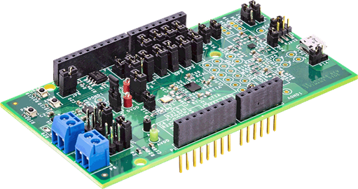
47 | * [EVAL-AD5940ELEC](https://www.analog.com/en/design-center/evaluation-hardware-and-software/evaluation-boards-kits/EVAL-AD5940ELCZ.html) is used for industrial application like Gas Detection with electrochemical sensor, Water Quality etc. It has on board socket for gas sensor and a BNC connector for PH sensor. The USB connector actually carries the analog signal from AD5940 which allows you to connect any other sensors so you can do either impedance measurement or used as potentiostat circuit. Find more introduction on [Wiki](https://wiki.analog.com/resources/eval/user-guides/eval-ad5940/hardware/eval-ad5940elcz).
48 | 
49 |
50 | ## Software
51 | Both IAR and Keil example projects are provided.
52 |
53 | On how to use the IAR project, follow [this link](https://wiki.analog.com/resources/eval/user-guides/eval-ad5940/tools/iar_setup_guide) from ADI Wiki.
54 |
55 | For Keil project, follow [this link](https://wiki.analog.com/resources/eval/user-guides/eval-ad5940/tools/keil_setup_guide).
56 |
57 | **Note: CMSIS pack is used in all examples, make sure you installed the pack no matter in Keil or IAR.**
58 |
59 |
60 | # License
61 | Copyright (c) 2017-2019 Analog Devices, Inc. All Rights Reserved.
62 |
--------------------------------------------------------------------------------
/examples/AD5940_Impedance_Adjustable_with_frequency/AD5940Main.c:
--------------------------------------------------------------------------------
1 | /*!
2 | *****************************************************************************
3 | @file: AD5940Main.c
4 | @author: Neo Xu
5 | @brief: Standard 4-wire or 2-wire impedance measurement example.
6 | -----------------------------------------------------------------------------
7 |
8 | Copyright (c) 2017-2019 Analog Devices, Inc. All Rights Reserved.
9 |
10 | This software is proprietary to Analog Devices, Inc. and its licensors.
11 | By using this software you agree to the terms of the associated
12 | Analog Devices Software License Agreement.
13 |
14 | *****************************************************************************/
15 | #include "Impedance.h"
16 |
17 | /**
18 | User could configure following parameters
19 | **/
20 |
21 | #define APPBUFF_SIZE 512
22 | uint32_t AppBuff[APPBUFF_SIZE];
23 |
24 | int32_t ImpedanceShowResult(uint32_t *pData, uint32_t DataCount)
25 | {
26 | float freq;
27 |
28 | fImpPol_Type *pImp = (fImpPol_Type*)pData;
29 | AppIMPCtrl(IMPCTRL_GETFREQ, &freq);
30 |
31 | printf("Freq:%.2f ", freq);
32 | /*Process data*/
33 | for(int i=0;iSeqStartAddr = 0;
93 | pImpedanceCfg->MaxSeqLen = 512; /* @todo add checker in function */
94 |
95 | pImpedanceCfg->RcalVal = 10000.0;
96 | pImpedanceCfg->SinFreq = 60000.0;
97 | pImpedanceCfg->FifoThresh = 4;
98 |
99 | /* Set switch matrix to onboard(EVAL-AD5940ELECZ) dummy sensor. */
100 | /* Note the RCAL0 resistor is 10kOhm. */
101 | pImpedanceCfg->DswitchSel = SWD_CE0;
102 | pImpedanceCfg->PswitchSel = SWP_RE0;
103 | pImpedanceCfg->NswitchSel = SWN_SE0;
104 | pImpedanceCfg->TswitchSel = SWT_SE0LOAD;
105 | /* The dummy sensor is as low as 5kOhm. We need to make sure RTIA is small enough that HSTIA won't be saturated. */
106 | pImpedanceCfg->HstiaRtiaSel = HSTIARTIA_5K;
107 |
108 | /* Configure the sweep function. */
109 | pImpedanceCfg->SweepCfg.SweepEn = bTRUE;
110 | pImpedanceCfg->SweepCfg.SweepStart = 1.0f; /* Start from 1kHz */
111 | pImpedanceCfg->SweepCfg.SweepStop = 200e3f; /* Stop at 100kHz */
112 | pImpedanceCfg->SweepCfg.SweepPoints = 101; /* Points is 101 */
113 | pImpedanceCfg->SweepCfg.SweepLog = bTRUE;
114 | /* Configure Power Mode. Use HP mode if frequency is higher than 80kHz. */
115 | pImpedanceCfg->PwrMod = AFEPWR_LP;
116 | /* Configure filters if necessary */
117 | pImpedanceCfg->ADCSinc3Osr = ADCSINC3OSR_2; /* Sample rate is 800kSPS/2 = 400kSPS */
118 | pImpedanceCfg->DftNum = DFTNUM_16384;
119 | pImpedanceCfg->DftSrc = DFTSRC_SINC3;
120 | }
121 |
122 | void AD5940_Main(void)
123 | {
124 | uint32_t temp;
125 | AD5940PlatformCfg();
126 | AD5940ImpedanceStructInit();
127 |
128 | AppIMPInit(AppBuff, APPBUFF_SIZE); /* Initialize IMP application. Provide a buffer, which is used to store sequencer commands */
129 | AppIMPCtrl(IMPCTRL_START, 0); /* Control IMP measurement to start. Second parameter has no meaning with this command. */
130 |
131 | while(1)
132 | {
133 | if(AD5940_GetMCUIntFlag())
134 | {
135 | AD5940_ClrMCUIntFlag();
136 | temp = APPBUFF_SIZE;
137 | AppIMPISR(AppBuff, &temp);
138 | ImpedanceShowResult(AppBuff, temp);
139 | }
140 | }
141 | }
142 |
143 |
--------------------------------------------------------------------------------
/examples/AD5940_SqrWaveVoltammetry/SqrWaveVoltammetry.h:
--------------------------------------------------------------------------------
1 | /*!
2 | *****************************************************************************
3 | @file: RampTest.H
4 | @author: $Author: nxu2 $
5 | @brief: Ramp Test header file.
6 | @version: $Revision: 766 $
7 | @date: $Date: 2017-08-21 14:09:35 +0100 (Mon, 21 Aug 2017) $
8 | -----------------------------------------------------------------------------
9 |
10 | Copyright (c) 2017-2019 Analog Devices, Inc. All Rights Reserved.
11 |
12 | This software is proprietary to Analog Devices, Inc. and its licensors.
13 | By using this software you agree to the terms of the associated
14 | Analog Devices Software License Agreement.
15 |
16 | *****************************************************************************/
17 | #ifndef _SWVTEST_H_
18 | #define _SWVTEST_H_
19 | #include "ad5940.h"
20 | #include
21 | #include "string.h"
22 | #include "math.h"
23 |
24 | /* Do not modify following parameters */
25 | #define ALIGIN_VOLT2LSB 0 /* Set it to 1 to align each voltage step to 1LSB of DAC. 0: step code is fractional. */
26 | #define DAC12BITVOLT_1LSB (2200.0f/4095) //mV
27 | #define DAC6BITVOLT_1LSB (DAC12BITVOLT_1LSB*64) //mV
28 |
29 | /**
30 | * The Ramp application related paramter structure
31 | */
32 | typedef struct
33 | {
34 | /* Common configurations for all kinds of Application. */
35 | BoolFlag bParaChanged; /**< Indicate to generate sequence again. It's auto cleared by AppBIAInit */
36 | uint32_t SeqStartAddr; /**< Initialaztion sequence start address in SRAM of AD5940 */
37 | uint32_t MaxSeqLen; /**< Limit the maximum sequence. */
38 | uint32_t SeqStartAddrCal; /**< Not used for Ramp.Calibration sequence start address in SRAM of AD5940 */
39 | uint32_t MaxSeqLenCal; /**< Not used for Ramp. */
40 | /* Application related parameters */
41 | float LFOSCClkFreq; /**< The clock frequency of Wakeup Timer in Hz. Typically it's 32kHz. Leave it here in case we calibrate clock in software method */
42 | float SysClkFreq; /**< The real frequency of system clock */
43 | float AdcClkFreq; /**< The real frequency of ADC clock */
44 | float RcalVal; /**< Rcal value in Ohm */
45 | float ADCRefVolt; /**< The real ADC voltage in mV. */
46 | /* Describe Ramp signal */
47 | float RampStartVolt; /**< The start voltage of ramp signal in mV */
48 | float RampPeakVolt; /**< The maximum or minimum voltage of ramp in mV */
49 | float VzeroStart; /**< The start voltage of Vzero in mV. Set it to 2400mV by default */
50 | float VzeroPeak; /**< The peak voltage of Vzero in mV. Set it to 200mV by default */
51 | uint32_t StepNumber; /**< Total number of steps. Limited to 4095. */
52 | /* Receive path configuration */
53 | float SampleDelay; /**< The time delay between update DAC and start ADC */
54 | uint32_t LPTIARtiaSel; /**< Select RTIA */
55 | float ExternalRtiaValue; /**< The optional external RTIA value in Ohm. Disconnect internal RTIA to use external RTIA. When using internal RTIA, this value is ignored. */
56 | uint32_t AdcPgaGain; /**< PGA Gain select from GNPGA_1, GNPGA_1_5, GNPGA_2, GNPGA_4, GNPGA_9 !!! We must ensure signal is in range of +-1.5V which is limited by ADC input stage */
57 | uint8_t ADCSinc3Osr; /**< We use data from SINC3 filter. */
58 | /* Digital related */
59 | uint32_t FifoThresh; /**< FIFO Threshold value */
60 | /* Private variables for internal usage */
61 | BoolFlag SWVInited; /**< If the program run firstly, generated initialization sequence commands */
62 | fImpPol_Type RtiaValue; /**< Calibrated Rtia value */
63 | SEQInfo_Type InitSeqInfo;
64 | SEQInfo_Type ADCSeqInfo;
65 | BoolFlag bFirstDACSeq; /**< Init DAC sequence */
66 | SEQInfo_Type DACSeqInfo; /**< The first DAC update sequence info */
67 | uint32_t CurrStepPos; /**< Current position */
68 | float DACCodePerStep; /**< DAC codes in square waveform */
69 | float DACCodePerRamp; /**< DAC codes needed to ramp increment */
70 | float CurrRampCode; /**< */
71 | float Frequency; /**< Frequency of square wave */
72 | float SqrWvAmplitude; /**< Set amplitude of square wave */
73 | float SqrWvRampIncrement; /**< Ramp increase in mV */
74 | uint32_t CurrVzeroCode;
75 | BoolFlag bDACCodeInc; /**< Increase DAC code. */
76 | BoolFlag bSqrWaveHiLevel; /**< Flag to indicate square wave high level */
77 | BoolFlag bRampOneDir; /**< Ramp in one direction only */
78 | BoolFlag StopRequired; /**< After FIFO is ready, stop the measurement sequence */
79 | enum _RampState{SWV_STATE0 = 0, SWV_STATE1, SWV_STATE2, SWV_STATE3, SWV_STATE4, SWV_STOP} RampState;
80 | }AppSWVCfg_Type;
81 |
82 | #define APPCTRL_START 0
83 | #define APPCTRL_STOPNOW 1
84 | #define APPCTRL_STOPSYNC 2
85 | #define APPCTRL_SHUTDOWN 3 /**< Note: shutdown here means turn off everything and put AFE to hibernate mode. The word 'SHUT DOWN' is only used here. */
86 |
87 | AD5940Err AppSWVInit(uint32_t *pBuffer, uint32_t BufferSize);
88 | AD5940Err AppSWVGetCfg(void *pCfg);
89 | AD5940Err AppSWVISR(void *pBuff, uint32_t *pCount);
90 | AD5940Err AppSWVCtrl(uint32_t Command, void *pPara);
91 | void AD5940_McuSetLow(void);
92 | void AD5940_McuSetHigh(void);
93 |
94 | #endif
95 |
--------------------------------------------------------------------------------
/examples/AD5940_WG/AD5940_WGSin_LPDAC.c:
--------------------------------------------------------------------------------
1 | /*!
2 | *****************************************************************************
3 | @file: AD5940_WGSin_LPDAC.c
4 | @author: $Author: nxu2 $
5 | @brief: Waveform generator(sin wave) example using LPDAC.
6 | @version: $Revision: 766 $
7 | @date: $Date: 2017-08-21 14:09:35 +0100 (Mon, 21 Aug 2017) $
8 | -----------------------------------------------------------------------------
9 |
10 | Copyright (c) 2017-2019 Analog Devices, Inc. All Rights Reserved.
11 |
12 | This software is proprietary to Analog Devices, Inc. and its licensors.
13 | By using this software you agree to the terms of the associated
14 | Analog Devices Software License Agreement.
15 |
16 | *****************************************************************************/
17 | #include "ad5940.h"
18 | #include
19 | #include "string.h"
20 | /**
21 | * This example is to generate sin wave on pin CE0 using waveform generator and LPDAC.
22 | * Signal generator simpley generates digital codes. The code can route to both
23 | * HSDAC and LPDAC. So, we can generate sin wave using both DAC.
24 | *
25 | * @note: LPDAC has limited bandwidth, do not use it to generate signal above 300Hz,
26 | * otherwise, you will see significant performance drop.
27 | * The DAC update rate parameter is decided by register HSDACCON.Rate. This also true
28 | * when using LPDAC as data sink.
29 | */
30 | #define SIN_AMPLITUDE 1100.0 /**< Signal amplitude in mV.*/
31 | #define SIN_FREQ 100.0 /**< 100Hz. Max is 300Hz */
32 | #define WG_CLOCK_HZ 32e3f /**< Waveform generator clock frequency. Equal to system clock. */
33 |
34 | void AD5940_Main(void)
35 | {
36 | AFERefCfg_Type aferef_cfg;
37 | CLKCfg_Type clk_cfg;
38 | LPDACCfg_Type lpdac_cfg;
39 | WGCfg_Type WgCfg;
40 | LPAmpCfg_Type lpamp_cfg;
41 | HSDACCfg_Type HsDacCfg;
42 |
43 | /* Use hardware reset */
44 | AD5940_HWReset();
45 | AD5940_Initialize();
46 | clk_cfg.ADCClkDiv = ADCCLKDIV_1;
47 | clk_cfg.ADCCLkSrc = ADCCLKSRC_HFOSC;
48 | clk_cfg.SysClkDiv = SYSCLKDIV_1;
49 | clk_cfg.SysClkSrc = SYSCLKSRC_HFOSC;
50 | clk_cfg.HfOSC32MHzMode = bFALSE;
51 | clk_cfg.HFOSCEn = bTRUE;
52 | clk_cfg.HFXTALEn = bFALSE;
53 | clk_cfg.LFOSCEn = bTRUE;
54 | AD5940_CLKCfg(&clk_cfg);
55 |
56 | aferef_cfg.HpBandgapEn = bTRUE;
57 | aferef_cfg.Hp1V1BuffEn = bTRUE;
58 | aferef_cfg.Hp1V8BuffEn = bTRUE;
59 | aferef_cfg.Disc1V1Cap = bFALSE;
60 | aferef_cfg.Disc1V8Cap = bFALSE;
61 | aferef_cfg.Hp1V8ThemBuff = bFALSE;
62 | aferef_cfg.Hp1V8Ilimit = bFALSE;
63 | aferef_cfg.Lp1V1BuffEn = bFALSE;
64 | aferef_cfg.Lp1V8BuffEn = bFALSE;
65 |
66 | /* LP reference control */
67 | aferef_cfg.LpBandgapEn = bTRUE;
68 | aferef_cfg.LpRefBufEn = bTRUE;
69 | aferef_cfg.LpRefBoostEn = bFALSE;
70 | AD5940_REFCfgS(&aferef_cfg);
71 |
72 | /* Configure LPDAC*/
73 | lpdac_cfg.LpdacSel = LPDAC0;
74 | lpdac_cfg.DataRst = bFALSE;
75 | lpdac_cfg.LpDacSW = LPDACSW_VBIAS2LPPA/*|LPDACSW_VBIAS2PIN*/|LPDACSW_VZERO2LPTIA/*|LPDACSW_VZERO2PIN*/;
76 | lpdac_cfg.LpDacRef = LPDACREF_2P5; /* Use internal 2.5V reference */
77 | lpdac_cfg.LpDacSrc = LPDACSRC_WG; /* Use data from waveform generator */
78 | lpdac_cfg.LpDacVbiasMux = LPDACVBIAS_12BIT;
79 | lpdac_cfg.LpDacVzeroMux = LPDACVZERO_6BIT; /* Use 6bit LPDAC for Vzero */
80 | lpdac_cfg.PowerEn = bTRUE; /* Enable LPDAC */
81 | lpdac_cfg.DacData12Bit = 0; /* Don't care, 12bit DAC data is from WG */
82 | lpdac_cfg.DacData6Bit = 32;
83 | AD5940_LPDACCfgS(&lpdac_cfg);
84 |
85 | /* Configure low power amplifiers */
86 | lpamp_cfg.LpAmpSel = LPAMP0;
87 | lpamp_cfg.LpAmpPwrMod = LPAMPPWR_NORM; /* Use normal power mode is enough */
88 | lpamp_cfg.LpPaPwrEn = bTRUE; /* Enable Potential amplifier */
89 | lpamp_cfg.LpTiaPwrEn = bFALSE; /* TIA is not used in this example */
90 | lpamp_cfg.LpTiaRf = LPTIARF_1M;
91 | lpamp_cfg.LpTiaRload = LPTIARLOAD_100R; /* don't care */
92 | lpamp_cfg.LpTiaRtia = LPTIARTIA_1K; /* don't care */
93 | lpamp_cfg.LpTiaSW = 0; /* don't care */
94 | AD5940_LPAMPCfgS(&lpamp_cfg);
95 |
96 | HsDacCfg.ExcitBufGain = EXCITBUFGAIN_2;
97 | HsDacCfg.HsDacGain = HSDACGAIN_1;
98 | HsDacCfg.HsDacUpdateRate = 7; /* DAC update rate equals to WG_CLK/HsDacUpdateRate */
99 | AD5940_HSDacCfgS(&HsDacCfg);
100 | /* Configure Waveform Generator */
101 | WgCfg.WgType = WGTYPE_SIN;
102 | WgCfg.GainCalEn = bFALSE;
103 | WgCfg.OffsetCalEn = bFALSE;
104 | WgCfg.SinCfg.SinFreqWord = AD5940_WGFreqWordCal(SIN_FREQ, WG_CLOCK_HZ);
105 | WgCfg.SinCfg.SinAmplitudeWord = (uint32_t)(SIN_AMPLITUDE/1100.0f*2047);
106 | WgCfg.SinCfg.SinOffsetWord = 0;
107 | WgCfg.SinCfg.SinPhaseWord = 0;
108 | AD5940_WGCfgS(&WgCfg);
109 |
110 | AD5940_AFEPwrBW(AFEPWR_LP, AFEBW_AUTOSET);
111 | AD5940_AFECtrlS(AFECTRL_WG, bTRUE);
112 |
113 | /* Change to 32kHz clock. LPDAC needs 32kHz clock for waveform generator */
114 | AD5940_LPModeEnS(bTRUE); /* Enter LP control mode. The registers are summarized to LPMODECON, so we can control some blocks conveniently */
115 | AD5940_LPModeClkS(LPMODECLK_LFOSC); /* Trigger switching system clock to 32kHz */
116 | AD5940_LPModeCtrlS(LPMODECTRL_NONE); /* Disable all */
117 | AD5940_LPModeCtrlS(LPMODECTRL_GLBBIASZ|LPMODECTRL_GLBBIASP|LPMODECTRL_HPREFPWR|LPMODECTRL_BUFHP1P8V|LPMODECTRL_BUFHP1P1V|LPMODECTRL_HFOSCEN);
118 | while(1);
119 | }
120 |
121 |
--------------------------------------------------------------------------------
/examples/AD5940_BIOZ-2Wire/BIOZ-2Wire.h:
--------------------------------------------------------------------------------
1 | /*!
2 | @file: BIOZ-2Wire.h
3 | @author: Neo Xu
4 | @brief: 4-wire BIOZ measurement header file.
5 | -----------------------------------------------------------------------------
6 |
7 | Copyright (c) 2017-2019 Analog Devices, Inc. All Rights Reserved.
8 |
9 | This software is proprietary to Analog Devices, Inc. and its licensors.
10 | By using this software you agree to the terms of the associated
11 | Analog Devices Software License Agreement.
12 |
13 | *****************************************************************************/
14 |
15 | #ifndef _BODYCOMPOSITION_H_
16 | #define _BODYCOMPOSITION_H_
17 | #include "ad5940.h"
18 | #include "stdio.h"
19 | #include "string.h"
20 | #include "math.h"
21 |
22 | #define MAXSWEEP_POINTS 100 /* Need to know how much buffer is needed to save RTIA calibration result */
23 |
24 | /*
25 | Note: this example will use SEQID_0 as measurement sequence, and use SEQID_1 as init sequence.
26 | SEQID_3 is used for calibration.
27 | */
28 |
29 | typedef struct
30 | {
31 | /* Common configurations for all kinds of Application. */
32 | BoolFlag bParaChanged; /* Indicate to generate sequence again. It's auto cleared by AppBIOZInit */
33 | uint32_t SeqStartAddr; /* Initialaztion sequence start address in SRAM of AD5940 */
34 | uint32_t MaxSeqLen; /* Limit the maximum sequence. */
35 | uint32_t SeqStartAddrCal; /* Measurement sequence start address in SRAM of AD5940 */
36 | uint32_t MaxSeqLenCal;
37 | /* Application related parameters */
38 | //BoolFlag bBioElecBoard; /* The code is same for BioElec board and AD5941Sens1 board. No changes are needed */
39 | BoolFlag ReDoRtiaCal; /* Set this flag to bTRUE when there is need to do calibration. */
40 | float SysClkFreq; /* The real frequency of system clock */
41 | float WuptClkFreq; /* The clock frequency of Wakeup Timer in Hz. Typically it's 32kHz. Leave it here in case we calibrate clock in software method */
42 | float AdcClkFreq; /* The real frequency of ADC clock */
43 | uint32_t FifoThresh; /* FIFO threshold. Should be N*2 */
44 | float BIOZODR; /* in Hz. ODR decides the period of WakeupTimer who will trigger sequencer periodically. DFT number and sample frequency decides the maxim ODR. */
45 | int32_t NumOfData; /* By default it's '-1'. If you want the engine stops after get NumofData, then set the value here. Otherwise, set it to '-1' which means never stop. */
46 | float SinFreq; /* Frequency of excitation signal */
47 | float RcalVal; /* Rcal value in Ohm */
48 | uint32_t PwrMod; /* Control Chip power mode(LP/HP) */
49 | float DacVoltPP; /* Final excitation voltage is DacVoltPP*DAC_PGA*EXCIT_GAIN, DAC_PGA= 1 or 0.2, EXCIT_GAIN=2 or 0.25. DAC output voltage in mV peak to peak. Maximum value is 800mVpp. Peak to peak voltage */
50 | uint32_t ExcitBufGain; /* Select from EXCITBUFGAIN_2, EXCITBUFGAIN_0P25 */
51 | uint32_t HsDacGain; /* Select from HSDACGAIN_1, HSDACGAIN_0P2 */
52 | uint32_t HsDacUpdateRate; /* DAC update rate is SystemCLoock/Divider. The available value is 7 to 255. Set to 7 for better performance */
53 | uint32_t ADCPgaGain; /* PGA Gain select from GNPGA_1, GNPGA_1_5, GNPGA_2, GNPGA_4, GNPGA_9 !!! We must ensure signal is in range of +-1.5V which is limited by ADC input stage */
54 | uint8_t ADCSinc3Osr; /* SINC3 OSR selection. ADCSINC3OSR_2, ADCSINC3OSR_4 */
55 | uint8_t ADCSinc2Osr; /* SINC2 OSR selection. ADCSINC2OSR_22...ADCSINC2OSR_1333 */
56 | uint32_t HstiaRtiaSel; /* Use internal RTIA, select from RTIA_INT_200, RTIA_INT_1K, RTIA_INT_5K, RTIA_INT_10K, RTIA_INT_20K, RTIA_INT_40K, RTIA_INT_80K, RTIA_INT_160K */
57 | uint32_t CtiaSel; /* Select CTIA in pF unit from 0 to 31pF */
58 |
59 | uint32_t DftNum; /* DFT number */
60 | uint32_t DftSrc; /* DFT Source */
61 | BoolFlag HanWinEn; /* Enable Hanning window */
62 |
63 | /* Switch Configuration */
64 | uint32_t DswitchSel;
65 | uint32_t PswitchSel;
66 | uint32_t NswitchSel;
67 | uint32_t TswitchSel;
68 |
69 | /* Sweep Function Control */
70 | SoftSweepCfg_Type SweepCfg;
71 | /* Private variables for internal usage */
72 | float SweepCurrFreq;
73 | float SweepNextFreq;
74 | fImpCar_Type RtiaCurrValue; /* Calibrated Rtia value at current frequency */
75 | fImpCar_Type RtiaCalTable[MAXSWEEP_POINTS]; /* Calibrated Rtia Value table */
76 | float FreqofData; /* The frequency of latest data sampled */
77 | BoolFlag BIOZInited; /* If the program run firstly, generated sequence commands */
78 | SEQInfo_Type InitSeqInfo;
79 | SEQInfo_Type MeasureSeqInfo;
80 | BoolFlag StopRequired; /* After FIFO is ready, stop the measurement sequence */
81 | uint32_t FifoDataCount; /* Count how many times impedance have been measured */
82 | /* End */
83 | }AppBIOZCfg_Type;
84 |
85 | #define BIOZCTRL_START 0
86 | #define BIOZCTRL_STOPNOW 1
87 | #define BIOZCTRL_STOPSYNC 2
88 | #define BIOZCTRL_GETFREQ 3 /* Get Current frequency of returned data from ISR */
89 | #define BIOZCTRL_SHUTDOWN 4 /* Note: shutdown here means turn off everything and put AFE to hibernate mode. The word 'SHUT DOWN' is only used here. */
90 |
91 | AD5940Err AppBIOZGetCfg(void *pCfg);
92 | AD5940Err AppBIOZInit(uint32_t *pBuffer, uint32_t BufferSize);
93 | AD5940Err AppBIOZISR(void *pBuff, uint32_t *pCount);
94 | AD5940Err AppBIOZCtrl(int32_t BcmCtrl, void *pPara);
95 | AD5940Err AppBIOZCheckFreq(float freq);
96 |
97 | #endif
98 |
--------------------------------------------------------------------------------
/examples/AD5940_BATImpedance/ADICUP3029/main.c:
--------------------------------------------------------------------------------
1 | /*
2 | Copyright (c) 2017-2019 Analog Devices, Inc. All Rights Reserved.
3 |
4 | This software is proprietary to Analog Devices, Inc. and its licensors.
5 | By using this software you agree to the terms of the associated
6 | Analog Devices Software License Agreement.
7 | */
8 |
9 | #include "stdio.h"
10 | #include "ADuCM3029.h"
11 | #include "AD5940.h"
12 |
13 | /* Functions that used to initialize MCU platform */
14 | uint32_t MCUPlatformInit(void *pCfg);
15 |
16 | int main(void)
17 | {
18 | void AD5940_Main(void);
19 | MCUPlatformInit(0);
20 | AD5940_MCUResourceInit(0);
21 | printf("Hello AD5940-Build Time:%s\n",__TIME__);
22 | AD5940_Main();
23 | }
24 |
25 | /* Below functions are used to initialize MCU Platform */
26 | uint32_t MCUPlatformInit(void *pCfg)
27 | {
28 | int UrtCfg(int iBaud);
29 |
30 | /*Stop watch dog timer(ADuCM3029)*/
31 | pADI_WDT0->CTL = 0xC9;
32 | /* Clock Configure */
33 | pADI_CLKG0_OSC->KEY = 0xCB14; // Select HFOSC as system clock.
34 | pADI_CLKG0_OSC->CTL = // Int 32khz LFOSC selected in LFMUX
35 | BITM_CLKG_OSC_CTL_HFOSCEN|BITM_CLKG_OSC_CTL_HFXTALEN;
36 |
37 | while((pADI_CLKG0_OSC->CTL&BITM_CLKG_OSC_CTL_HFXTALOK) == 0);
38 |
39 | pADI_CLKG0_OSC->KEY = 0xCB14;
40 | pADI_CLKG0_CLK->CTL0 = 0x201; /* Select XTAL as system clock */
41 | pADI_CLKG0_CLK->CTL1 = 0; // ACLK,PCLK,HCLK divided by 1
42 | pADI_CLKG0_CLK->CTL5 = 0x00; // Enable clock to all peripherals - no clock gating
43 |
44 | UrtCfg(230400);/*Baud rate: 230400*/
45 | return 1;
46 | }
47 |
48 | /**
49 | @brief int UrtCfg(int iBaud, int iBits, int iFormat)
50 | ==========Configure the UART.
51 | @param iBaud :{B1200,B2200,B2400,B4800,B9600,B19200,B38400,B57600,B115200,B230400,B430800} \n
52 | Set iBaud to the baudrate required:
53 | Values usually: 1200, 2200 (for HART), 2400, 4800, 9600,
54 | 19200, 38400, 57600, 115200, 230400, 430800, or type in baud-rate directly
55 | @note
56 | - Powers up UART if not powered up.
57 | - Standard baudrates are accurate to better than 0.1% plus clock error.\n
58 | - Non standard baudrates are accurate to better than 1% plus clock error.
59 | @warning - If an external clock is used for the system the ullRtClk must be modified with \n
60 | the speed of the clock used.
61 | **/
62 |
63 | int UrtCfg(int iBaud)
64 | {
65 | int iBits = 3;//8bits,
66 | int iFormat = 0;//, int iBits, int iFormat
67 | int i1;
68 | int iDiv;
69 | int iRtC;
70 | int iOSR;
71 | int iPllMulValue;
72 | unsigned long long ullRtClk = 16000000; // The root clock speed
73 |
74 |
75 | /*Setup P0[11:10] as UART pins*/
76 | pADI_GPIO0->CFG = (1<<22)|(1<<20)|(pADI_GPIO0->CFG&(~((3<<22)|(3<<20))));
77 |
78 | iDiv = (pADI_CLKG0_CLK->CTL1& BITM_CLKG_CLK_CTL1_PCLKDIVCNT); // Read UART clock as set by CLKCON1[10:8]
79 | iDiv = iDiv>>8;
80 | if (iDiv == 0)
81 | iDiv = 1;
82 | iRtC = (pADI_CLKG0_CLK->CTL0& BITM_CLKG_CLK_CTL0_CLKMUX); // Check what is the root clock
83 |
84 | switch (iRtC)
85 | {
86 | case 0: // HFOSC selected
87 | ullRtClk = 26000000;
88 | break;
89 |
90 | case 1: // HFXTAL selected
91 | if ((pADI_CLKG0_CLK->CTL0 & 0x200)==0x200) // 26Mhz XTAL used
92 | ullRtClk = 26000000;
93 | else
94 | ullRtClk = 16000000; // Assume 16MHz XTAL
95 | break;
96 |
97 | case 2: // SPLL output
98 | iPllMulValue = (pADI_CLKG0_CLK->CTL3 & // Check muliplication factor in PLL settings
99 | BITM_CLKG_CLK_CTL3_SPLLNSEL); // bits[4:0]. Assume div value of 0xD in bits [14:11]
100 | ullRtClk = (iPllMulValue *1000000); // Assume straight multiplication by pADI_CLKG0_CLK->CTL3[4:0]
101 | break;
102 |
103 | case 3:
104 | ullRtClk = 26000000; //External clock is assumed to be 26MhZ, if different
105 | break; //clock speed is used, this should be changed
106 |
107 | default:
108 | break;
109 | }
110 | // iOSR = (pADI_UART0->COMLCR2 & 0x3);
111 | // iOSR = 2^(2+iOSR);
112 | pADI_UART0->COMLCR2 = 0x3;
113 | iOSR = 32;
114 | //i1 = (ullRtClk/(iOSR*iDiv))/iBaud; // UART baud rate clock source is PCLK divided by OSR
115 | i1 = (ullRtClk/(iOSR*iDiv))/iBaud-1; //for bigger M and N value
116 | pADI_UART0->COMDIV = i1;
117 |
118 | pADI_UART0->COMFBR = 0x8800|(((((2048/(iOSR*iDiv))*ullRtClk)/i1)/iBaud)-2048);
119 | pADI_UART0->COMIEN = 0;
120 | pADI_UART0->COMLCR = (iFormat&0x3c)|(iBits&3);
121 |
122 |
123 | pADI_UART0->COMFCR = (BITM_UART_COMFCR_RFTRIG & 0/*RX_FIFO_1BYTE*/ ) |BITM_UART_COMFCR_FIFOEN;
124 | pADI_UART0->COMFCR |= BITM_UART_COMFCR_RFCLR|BITM_UART_COMFCR_TFCLR; // Clear the UART FIFOs
125 | pADI_UART0->COMFCR &= ~(BITM_UART_COMFCR_RFCLR|BITM_UART_COMFCR_TFCLR); // Disable clearing mechanism
126 |
127 | NVIC_EnableIRQ(UART_EVT_IRQn); // Enable UART interrupt source in NVIC
128 | pADI_UART0->COMIEN = BITM_UART_COMIEN_ERBFI|BITM_UART_COMIEN_ELSI; /* Rx Interrupt */
129 | return pADI_UART0->COMLSR;
130 | }
131 | #include "stdio.h"
132 | #ifdef __ICCARM__
133 | int putchar(int c)
134 | #else
135 | int fputc(int c, FILE *f)
136 | #endif
137 | {
138 | pADI_UART0->COMTX = c;
139 | while((pADI_UART0->COMLSR&0x20) == 0);// tx fifo empty
140 | return c;
141 | }
142 |
--------------------------------------------------------------------------------
/examples/AD5940_WG/ADICUP3029/main.c:
--------------------------------------------------------------------------------
1 | /*
2 |
3 | Copyright (c) 2017-2019 Analog Devices, Inc. All Rights Reserved.
4 |
5 | This software is proprietary to Analog Devices, Inc. and its licensors.
6 | By using this software you agree to the terms of the associated
7 | Analog Devices Software License Agreement.
8 |
9 | */
10 |
11 | #include "stdio.h"
12 | #include "ADuCM3029.h"
13 | #include "AD5940.h"
14 |
15 | /* Functions that used to initialize MCU platform */
16 | uint32_t MCUPlatformInit(void *pCfg);
17 |
18 | int main(void)
19 | {
20 | void AD5940_Main(void);
21 | MCUPlatformInit(0);
22 | AD5940_MCUResourceInit(0);
23 | printf("Hello AD5940-Build Time:%s\n",__TIME__);
24 | AD5940_Main();
25 | }
26 |
27 | /* Below functions are used to initialize MCU Platform */
28 | uint32_t MCUPlatformInit(void *pCfg)
29 | {
30 | int UrtCfg(int iBaud);
31 |
32 | /*Stop watch dog timer(ADuCM3029)*/
33 | pADI_WDT0->CTL = 0xC9;
34 | /* Clock Configure */
35 | pADI_CLKG0_OSC->KEY = 0xCB14; // Select HFOSC as system clock.
36 | pADI_CLKG0_OSC->CTL = // Int 32khz LFOSC selected in LFMUX
37 | BITM_CLKG_OSC_CTL_HFOSCEN|BITM_CLKG_OSC_CTL_HFXTALEN;
38 |
39 | while((pADI_CLKG0_OSC->CTL&BITM_CLKG_OSC_CTL_HFXTALOK) == 0);
40 |
41 | pADI_CLKG0_OSC->KEY = 0xCB14;
42 | pADI_CLKG0_CLK->CTL0 = 0x201; /* Select XTAL as system clock */
43 | pADI_CLKG0_CLK->CTL1 = 0; // ACLK,PCLK,HCLK divided by 1
44 | pADI_CLKG0_CLK->CTL5 = 0x00; // Enable clock to all peripherals - no clock gating
45 |
46 | UrtCfg(230400);/*Baud rate: 230400*/
47 | return 1;
48 | }
49 |
50 | /**
51 | @brief int UrtCfg(int iBaud, int iBits, int iFormat)
52 | ==========Configure the UART.
53 | @param iBaud :{B1200,B2200,B2400,B4800,B9600,B19200,B38400,B57600,B115200,B230400,B430800} \n
54 | Set iBaud to the baudrate required:
55 | Values usually: 1200, 2200 (for HART), 2400, 4800, 9600,
56 | 19200, 38400, 57600, 115200, 230400, 430800, or type in baud-rate directly
57 | @note
58 | - Powers up UART if not powered up.
59 | - Standard baudrates are accurate to better than 0.1% plus clock error.\n
60 | - Non standard baudrates are accurate to better than 1% plus clock error.
61 | @warning - If an external clock is used for the system the ullRtClk must be modified with \n
62 | the speed of the clock used.
63 | **/
64 |
65 | int UrtCfg(int iBaud)
66 | {
67 | int iBits = 3;//8bits,
68 | int iFormat = 0;//, int iBits, int iFormat
69 | int i1;
70 | int iDiv;
71 | int iRtC;
72 | int iOSR;
73 | int iPllMulValue;
74 | unsigned long long ullRtClk = 16000000; // The root clock speed
75 |
76 |
77 | /*Setup P0[11:10] as UART pins*/
78 | pADI_GPIO0->CFG = (1<<22)|(1<<20)|(pADI_GPIO0->CFG&(~((3<<22)|(3<<20))));
79 |
80 | iDiv = (pADI_CLKG0_CLK->CTL1& BITM_CLKG_CLK_CTL1_PCLKDIVCNT); // Read UART clock as set by CLKCON1[10:8]
81 | iDiv = iDiv>>8;
82 | if (iDiv == 0)
83 | iDiv = 1;
84 | iRtC = (pADI_CLKG0_CLK->CTL0& BITM_CLKG_CLK_CTL0_CLKMUX); // Check what is the root clock
85 |
86 | switch (iRtC)
87 | {
88 | case 0: // HFOSC selected
89 | ullRtClk = 26000000;
90 | break;
91 |
92 | case 1: // HFXTAL selected
93 | if ((pADI_CLKG0_CLK->CTL0 & 0x200)==0x200) // 26Mhz XTAL used
94 | ullRtClk = 26000000;
95 | else
96 | ullRtClk = 16000000; // Assume 16MHz XTAL
97 | break;
98 |
99 | case 2: // SPLL output
100 | iPllMulValue = (pADI_CLKG0_CLK->CTL3 & // Check muliplication factor in PLL settings
101 | BITM_CLKG_CLK_CTL3_SPLLNSEL); // bits[4:0]. Assume div value of 0xD in bits [14:11]
102 | ullRtClk = (iPllMulValue *1000000); // Assume straight multiplication by pADI_CLKG0_CLK->CTL3[4:0]
103 | break;
104 |
105 | case 3:
106 | ullRtClk = 26000000; //External clock is assumed to be 26MhZ, if different
107 | break; //clock speed is used, this should be changed
108 |
109 | default:
110 | break;
111 | }
112 | // iOSR = (pADI_UART0->COMLCR2 & 0x3);
113 | // iOSR = 2^(2+iOSR);
114 | pADI_UART0->COMLCR2 = 0x3;
115 | iOSR = 32;
116 | //i1 = (ullRtClk/(iOSR*iDiv))/iBaud; // UART baud rate clock source is PCLK divided by OSR
117 | i1 = (ullRtClk/(iOSR*iDiv))/iBaud-1; //for bigger M and N value
118 | pADI_UART0->COMDIV = i1;
119 |
120 | pADI_UART0->COMFBR = 0x8800|(((((2048/(iOSR*iDiv))*ullRtClk)/i1)/iBaud)-2048);
121 | pADI_UART0->COMIEN = 0;
122 | pADI_UART0->COMLCR = (iFormat&0x3c)|(iBits&3);
123 |
124 |
125 | pADI_UART0->COMFCR = (BITM_UART_COMFCR_RFTRIG & 0/*RX_FIFO_1BYTE*/ ) |BITM_UART_COMFCR_FIFOEN;
126 | pADI_UART0->COMFCR |= BITM_UART_COMFCR_RFCLR|BITM_UART_COMFCR_TFCLR; // Clear the UART FIFOs
127 | pADI_UART0->COMFCR &= ~(BITM_UART_COMFCR_RFCLR|BITM_UART_COMFCR_TFCLR); // Disable clearing mechanism
128 |
129 | NVIC_EnableIRQ(UART_EVT_IRQn); // Enable UART interrupt source in NVIC
130 | pADI_UART0->COMIEN = BITM_UART_COMIEN_ERBFI|BITM_UART_COMIEN_ELSI; /* Rx Interrupt */
131 | return pADI_UART0->COMLSR;
132 | }
133 | #include "stdio.h"
134 | #ifdef __ICCARM__
135 | int putchar(int c)
136 | #else
137 | int fputc(int c, FILE *f)
138 | #endif
139 | {
140 | pADI_UART0->COMTX = c;
141 | while((pADI_UART0->COMLSR&0x20) == 0);// tx fifo empty
142 | return c;
143 | }
144 |
--------------------------------------------------------------------------------
/examples/AD5940_ADC/ADICUP3029/main.c:
--------------------------------------------------------------------------------
1 | /*
2 |
3 | Copyright (c) 2017-2019 Analog Devices, Inc. All Rights Reserved.
4 |
5 | This software is proprietary to Analog Devices, Inc. and its licensors.
6 | By using this software you agree to the terms of the associated
7 | Analog Devices Software License Agreement.
8 |
9 | */
10 |
11 | #include "stdio.h"
12 | #include "ADuCM3029.h"
13 | #include "AD5940.h"
14 |
15 | /* Functions that used to initialize MCU platform */
16 | uint32_t MCUPlatformInit(void *pCfg);
17 |
18 | int main(void)
19 | {
20 | void AD5940_Main(void);
21 | MCUPlatformInit(0);
22 | AD5940_MCUResourceInit(0);
23 | printf("Hello AD5940-Build Time:%s\n",__TIME__);
24 | AD5940_Main();
25 | }
26 |
27 | /* Below functions are used to initialize MCU Platform */
28 | uint32_t MCUPlatformInit(void *pCfg)
29 | {
30 | int UrtCfg(int iBaud);
31 |
32 | /*Stop watch dog timer(ADuCM3029)*/
33 | pADI_WDT0->CTL = 0xC9;
34 | /* Clock Configure */
35 | pADI_CLKG0_OSC->KEY = 0xCB14; // Select HFOSC as system clock.
36 | pADI_CLKG0_OSC->CTL = // Int 32khz LFOSC selected in LFMUX
37 | BITM_CLKG_OSC_CTL_HFOSCEN|BITM_CLKG_OSC_CTL_HFXTALEN;
38 |
39 | while((pADI_CLKG0_OSC->CTL&BITM_CLKG_OSC_CTL_HFXTALOK) == 0);
40 |
41 | pADI_CLKG0_OSC->KEY = 0xCB14;
42 | pADI_CLKG0_CLK->CTL0 = 0x201; /* Select XTAL as system clock */
43 | pADI_CLKG0_CLK->CTL1 = 0; // ACLK,PCLK,HCLK divided by 1
44 | pADI_CLKG0_CLK->CTL5 = 0x00; // Enable clock to all peripherals - no clock gating
45 |
46 | UrtCfg(230400);/*Baud rate: 230400*/
47 | return 1;
48 | }
49 |
50 | /**
51 | @brief int UrtCfg(int iBaud, int iBits, int iFormat)
52 | ==========Configure the UART.
53 | @param iBaud :{B1200,B2200,B2400,B4800,B9600,B19200,B38400,B57600,B115200,B230400,B430800} \n
54 | Set iBaud to the baudrate required:
55 | Values usually: 1200, 2200 (for HART), 2400, 4800, 9600,
56 | 19200, 38400, 57600, 115200, 230400, 430800, or type in baud-rate directly
57 | @note
58 | - Powers up UART if not powered up.
59 | - Standard baudrates are accurate to better than 0.1% plus clock error.\n
60 | - Non standard baudrates are accurate to better than 1% plus clock error.
61 | @warning - If an external clock is used for the system the ullRtClk must be modified with \n
62 | the speed of the clock used.
63 | **/
64 |
65 | int UrtCfg(int iBaud)
66 | {
67 | int iBits = 3;//8bits,
68 | int iFormat = 0;//, int iBits, int iFormat
69 | int i1;
70 | int iDiv;
71 | int iRtC;
72 | int iOSR;
73 | int iPllMulValue;
74 | unsigned long long ullRtClk = 16000000; // The root clock speed
75 |
76 |
77 | /*Setup P0[11:10] as UART pins*/
78 | pADI_GPIO0->CFG = (1<<22)|(1<<20)|(pADI_GPIO0->CFG&(~((3<<22)|(3<<20))));
79 |
80 | iDiv = (pADI_CLKG0_CLK->CTL1& BITM_CLKG_CLK_CTL1_PCLKDIVCNT); // Read UART clock as set by CLKCON1[10:8]
81 | iDiv = iDiv>>8;
82 | if (iDiv == 0)
83 | iDiv = 1;
84 | iRtC = (pADI_CLKG0_CLK->CTL0& BITM_CLKG_CLK_CTL0_CLKMUX); // Check what is the root clock
85 |
86 | switch (iRtC)
87 | {
88 | case 0: // HFOSC selected
89 | ullRtClk = 26000000;
90 | break;
91 |
92 | case 1: // HFXTAL selected
93 | if ((pADI_CLKG0_CLK->CTL0 & 0x200)==0x200) // 26Mhz XTAL used
94 | ullRtClk = 26000000;
95 | else
96 | ullRtClk = 16000000; // Assume 16MHz XTAL
97 | break;
98 |
99 | case 2: // SPLL output
100 | iPllMulValue = (pADI_CLKG0_CLK->CTL3 & // Check muliplication factor in PLL settings
101 | BITM_CLKG_CLK_CTL3_SPLLNSEL); // bits[4:0]. Assume div value of 0xD in bits [14:11]
102 | ullRtClk = (iPllMulValue *1000000); // Assume straight multiplication by pADI_CLKG0_CLK->CTL3[4:0]
103 | break;
104 |
105 | case 3:
106 | ullRtClk = 26000000; //External clock is assumed to be 26MhZ, if different
107 | break; //clock speed is used, this should be changed
108 |
109 | default:
110 | break;
111 | }
112 | // iOSR = (pADI_UART0->COMLCR2 & 0x3);
113 | // iOSR = 2^(2+iOSR);
114 | pADI_UART0->COMLCR2 = 0x3;
115 | iOSR = 32;
116 | //i1 = (ullRtClk/(iOSR*iDiv))/iBaud; // UART baud rate clock source is PCLK divided by OSR
117 | i1 = (ullRtClk/(iOSR*iDiv))/iBaud-1; //for bigger M and N value
118 | pADI_UART0->COMDIV = i1;
119 |
120 | pADI_UART0->COMFBR = 0x8800|(((((2048/(iOSR*iDiv))*ullRtClk)/i1)/iBaud)-2048);
121 | pADI_UART0->COMIEN = 0;
122 | pADI_UART0->COMLCR = (iFormat&0x3c)|(iBits&3);
123 |
124 |
125 | pADI_UART0->COMFCR = (BITM_UART_COMFCR_RFTRIG & 0/*RX_FIFO_1BYTE*/ ) |BITM_UART_COMFCR_FIFOEN;
126 | pADI_UART0->COMFCR |= BITM_UART_COMFCR_RFCLR|BITM_UART_COMFCR_TFCLR; // Clear the UART FIFOs
127 | pADI_UART0->COMFCR &= ~(BITM_UART_COMFCR_RFCLR|BITM_UART_COMFCR_TFCLR); // Disable clearing mechanism
128 |
129 | NVIC_EnableIRQ(UART_EVT_IRQn); // Enable UART interrupt source in NVIC
130 | pADI_UART0->COMIEN = BITM_UART_COMIEN_ERBFI|BITM_UART_COMIEN_ELSI; /* Rx Interrupt */
131 | return pADI_UART0->COMLSR;
132 | }
133 | #include "stdio.h"
134 | #ifdef __ICCARM__
135 | int putchar(int c)
136 | #else
137 | int fputc(int c, FILE *f)
138 | #endif
139 | {
140 | pADI_UART0->COMTX = c;
141 | while((pADI_UART0->COMLSR&0x20) == 0);// tx fifo empty
142 | return c;
143 | }
144 |
--------------------------------------------------------------------------------
/examples/AD5940_BIA/ADICUP3029/main.c:
--------------------------------------------------------------------------------
1 | /*
2 |
3 | Copyright (c) 2017-2019 Analog Devices, Inc. All Rights Reserved.
4 |
5 | This software is proprietary to Analog Devices, Inc. and its licensors.
6 | By using this software you agree to the terms of the associated
7 | Analog Devices Software License Agreement.
8 |
9 | */
10 |
11 | #include "stdio.h"
12 | #include "ADuCM3029.h"
13 | #include "AD5940.h"
14 |
15 | /* Functions that used to initialize MCU platform */
16 | uint32_t MCUPlatformInit(void *pCfg);
17 |
18 | int main(void)
19 | {
20 | void AD5940_Main(void);
21 | MCUPlatformInit(0);
22 | AD5940_MCUResourceInit(0);
23 | printf("Hello AD5940-Build Time:%s\n",__TIME__);
24 | AD5940_Main();
25 | }
26 |
27 | /* Below functions are used to initialize MCU Platform */
28 | uint32_t MCUPlatformInit(void *pCfg)
29 | {
30 | int UrtCfg(int iBaud);
31 |
32 | /*Stop watch dog timer(ADuCM3029)*/
33 | pADI_WDT0->CTL = 0xC9;
34 | /* Clock Configure */
35 | pADI_CLKG0_OSC->KEY = 0xCB14; // Select HFOSC as system clock.
36 | pADI_CLKG0_OSC->CTL = // Int 32khz LFOSC selected in LFMUX
37 | BITM_CLKG_OSC_CTL_HFOSCEN|BITM_CLKG_OSC_CTL_HFXTALEN;
38 |
39 | while((pADI_CLKG0_OSC->CTL&BITM_CLKG_OSC_CTL_HFXTALOK) == 0);
40 |
41 | pADI_CLKG0_OSC->KEY = 0xCB14;
42 | pADI_CLKG0_CLK->CTL0 = 0x201; /* Select XTAL as system clock */
43 | pADI_CLKG0_CLK->CTL1 = 0; // ACLK,PCLK,HCLK divided by 1
44 | pADI_CLKG0_CLK->CTL5 = 0x00; // Enable clock to all peripherals - no clock gating
45 |
46 | UrtCfg(230400);/*Baud rate: 230400*/
47 | return 1;
48 | }
49 |
50 | /**
51 | @brief int UrtCfg(int iBaud, int iBits, int iFormat)
52 | ==========Configure the UART.
53 | @param iBaud :{B1200,B2200,B2400,B4800,B9600,B19200,B38400,B57600,B115200,B230400,B430800} \n
54 | Set iBaud to the baudrate required:
55 | Values usually: 1200, 2200 (for HART), 2400, 4800, 9600,
56 | 19200, 38400, 57600, 115200, 230400, 430800, or type in baud-rate directly
57 | @note
58 | - Powers up UART if not powered up.
59 | - Standard baudrates are accurate to better than 0.1% plus clock error.\n
60 | - Non standard baudrates are accurate to better than 1% plus clock error.
61 | @warning - If an external clock is used for the system the ullRtClk must be modified with \n
62 | the speed of the clock used.
63 | **/
64 |
65 | int UrtCfg(int iBaud)
66 | {
67 | int iBits = 3;//8bits,
68 | int iFormat = 0;//, int iBits, int iFormat
69 | int i1;
70 | int iDiv;
71 | int iRtC;
72 | int iOSR;
73 | int iPllMulValue;
74 | unsigned long long ullRtClk = 16000000; // The root clock speed
75 |
76 |
77 | /*Setup P0[11:10] as UART pins*/
78 | pADI_GPIO0->CFG = (1<<22)|(1<<20)|(pADI_GPIO0->CFG&(~((3<<22)|(3<<20))));
79 |
80 | iDiv = (pADI_CLKG0_CLK->CTL1& BITM_CLKG_CLK_CTL1_PCLKDIVCNT); // Read UART clock as set by CLKCON1[10:8]
81 | iDiv = iDiv>>8;
82 | if (iDiv == 0)
83 | iDiv = 1;
84 | iRtC = (pADI_CLKG0_CLK->CTL0& BITM_CLKG_CLK_CTL0_CLKMUX); // Check what is the root clock
85 |
86 | switch (iRtC)
87 | {
88 | case 0: // HFOSC selected
89 | ullRtClk = 26000000;
90 | break;
91 |
92 | case 1: // HFXTAL selected
93 | if ((pADI_CLKG0_CLK->CTL0 & 0x200)==0x200) // 26Mhz XTAL used
94 | ullRtClk = 26000000;
95 | else
96 | ullRtClk = 16000000; // Assume 16MHz XTAL
97 | break;
98 |
99 | case 2: // SPLL output
100 | iPllMulValue = (pADI_CLKG0_CLK->CTL3 & // Check muliplication factor in PLL settings
101 | BITM_CLKG_CLK_CTL3_SPLLNSEL); // bits[4:0]. Assume div value of 0xD in bits [14:11]
102 | ullRtClk = (iPllMulValue *1000000); // Assume straight multiplication by pADI_CLKG0_CLK->CTL3[4:0]
103 | break;
104 |
105 | case 3:
106 | ullRtClk = 26000000; //External clock is assumed to be 26MhZ, if different
107 | break; //clock speed is used, this should be changed
108 |
109 | default:
110 | break;
111 | }
112 | // iOSR = (pADI_UART0->COMLCR2 & 0x3);
113 | // iOSR = 2^(2+iOSR);
114 | pADI_UART0->COMLCR2 = 0x3;
115 | iOSR = 32;
116 | //i1 = (ullRtClk/(iOSR*iDiv))/iBaud; // UART baud rate clock source is PCLK divided by OSR
117 | i1 = (ullRtClk/(iOSR*iDiv))/iBaud-1; //for bigger M and N value
118 | pADI_UART0->COMDIV = i1;
119 |
120 | pADI_UART0->COMFBR = 0x8800|(((((2048/(iOSR*iDiv))*ullRtClk)/i1)/iBaud)-2048);
121 | pADI_UART0->COMIEN = 0;
122 | pADI_UART0->COMLCR = (iFormat&0x3c)|(iBits&3);
123 |
124 |
125 | pADI_UART0->COMFCR = (BITM_UART_COMFCR_RFTRIG & 0/*RX_FIFO_1BYTE*/ ) |BITM_UART_COMFCR_FIFOEN;
126 | pADI_UART0->COMFCR |= BITM_UART_COMFCR_RFCLR|BITM_UART_COMFCR_TFCLR; // Clear the UART FIFOs
127 | pADI_UART0->COMFCR &= ~(BITM_UART_COMFCR_RFCLR|BITM_UART_COMFCR_TFCLR); // Disable clearing mechanism
128 |
129 | NVIC_EnableIRQ(UART_EVT_IRQn); // Enable UART interrupt source in NVIC
130 | pADI_UART0->COMIEN = BITM_UART_COMIEN_ERBFI|BITM_UART_COMIEN_ELSI; /* Rx Interrupt */
131 | return pADI_UART0->COMLSR;
132 | }
133 | #include "stdio.h"
134 | #ifdef __ICCARM__
135 | int putchar(int c)
136 | #else
137 | int fputc(int c, FILE *f)
138 | #endif
139 | {
140 | pADI_UART0->COMTX = c;
141 | while((pADI_UART0->COMLSR&0x20) == 0);// tx fifo empty
142 | return c;
143 | }
144 |
--------------------------------------------------------------------------------
/examples/AD5940_DFT/ADICUP3029/main.c:
--------------------------------------------------------------------------------
1 | /*
2 |
3 | Copyright (c) 2017-2019 Analog Devices, Inc. All Rights Reserved.
4 |
5 | This software is proprietary to Analog Devices, Inc. and its licensors.
6 | By using this software you agree to the terms of the associated
7 | Analog Devices Software License Agreement.
8 |
9 | */
10 |
11 | #include "stdio.h"
12 | #include "ADuCM3029.h"
13 | #include "AD5940.h"
14 |
15 | /* Functions that used to initialize MCU platform */
16 | uint32_t MCUPlatformInit(void *pCfg);
17 |
18 | int main(void)
19 | {
20 | void AD5940_Main(void);
21 | MCUPlatformInit(0);
22 | AD5940_MCUResourceInit(0);
23 | printf("Hello AD5940-Build Time:%s\n",__TIME__);
24 | AD5940_Main();
25 | }
26 |
27 | /* Below functions are used to initialize MCU Platform */
28 | uint32_t MCUPlatformInit(void *pCfg)
29 | {
30 | int UrtCfg(int iBaud);
31 |
32 | /*Stop watch dog timer(ADuCM3029)*/
33 | pADI_WDT0->CTL = 0xC9;
34 | /* Clock Configure */
35 | pADI_CLKG0_OSC->KEY = 0xCB14; // Select HFOSC as system clock.
36 | pADI_CLKG0_OSC->CTL = // Int 32khz LFOSC selected in LFMUX
37 | BITM_CLKG_OSC_CTL_HFOSCEN|BITM_CLKG_OSC_CTL_HFXTALEN;
38 |
39 | while((pADI_CLKG0_OSC->CTL&BITM_CLKG_OSC_CTL_HFXTALOK) == 0);
40 |
41 | pADI_CLKG0_OSC->KEY = 0xCB14;
42 | pADI_CLKG0_CLK->CTL0 = 0x201; /* Select XTAL as system clock */
43 | pADI_CLKG0_CLK->CTL1 = 0; // ACLK,PCLK,HCLK divided by 1
44 | pADI_CLKG0_CLK->CTL5 = 0x00; // Enable clock to all peripherals - no clock gating
45 |
46 | UrtCfg(230400);/*Baud rate: 230400*/
47 | return 1;
48 | }
49 |
50 | /**
51 | @brief int UrtCfg(int iBaud, int iBits, int iFormat)
52 | ==========Configure the UART.
53 | @param iBaud :{B1200,B2200,B2400,B4800,B9600,B19200,B38400,B57600,B115200,B230400,B430800} \n
54 | Set iBaud to the baudrate required:
55 | Values usually: 1200, 2200 (for HART), 2400, 4800, 9600,
56 | 19200, 38400, 57600, 115200, 230400, 430800, or type in baud-rate directly
57 | @note
58 | - Powers up UART if not powered up.
59 | - Standard baudrates are accurate to better than 0.1% plus clock error.\n
60 | - Non standard baudrates are accurate to better than 1% plus clock error.
61 | @warning - If an external clock is used for the system the ullRtClk must be modified with \n
62 | the speed of the clock used.
63 | **/
64 |
65 | int UrtCfg(int iBaud)
66 | {
67 | int iBits = 3;//8bits,
68 | int iFormat = 0;//, int iBits, int iFormat
69 | int i1;
70 | int iDiv;
71 | int iRtC;
72 | int iOSR;
73 | int iPllMulValue;
74 | unsigned long long ullRtClk = 16000000; // The root clock speed
75 |
76 |
77 | /*Setup P0[11:10] as UART pins*/
78 | pADI_GPIO0->CFG = (1<<22)|(1<<20)|(pADI_GPIO0->CFG&(~((3<<22)|(3<<20))));
79 |
80 | iDiv = (pADI_CLKG0_CLK->CTL1& BITM_CLKG_CLK_CTL1_PCLKDIVCNT); // Read UART clock as set by CLKCON1[10:8]
81 | iDiv = iDiv>>8;
82 | if (iDiv == 0)
83 | iDiv = 1;
84 | iRtC = (pADI_CLKG0_CLK->CTL0& BITM_CLKG_CLK_CTL0_CLKMUX); // Check what is the root clock
85 |
86 | switch (iRtC)
87 | {
88 | case 0: // HFOSC selected
89 | ullRtClk = 26000000;
90 | break;
91 |
92 | case 1: // HFXTAL selected
93 | if ((pADI_CLKG0_CLK->CTL0 & 0x200)==0x200) // 26Mhz XTAL used
94 | ullRtClk = 26000000;
95 | else
96 | ullRtClk = 16000000; // Assume 16MHz XTAL
97 | break;
98 |
99 | case 2: // SPLL output
100 | iPllMulValue = (pADI_CLKG0_CLK->CTL3 & // Check muliplication factor in PLL settings
101 | BITM_CLKG_CLK_CTL3_SPLLNSEL); // bits[4:0]. Assume div value of 0xD in bits [14:11]
102 | ullRtClk = (iPllMulValue *1000000); // Assume straight multiplication by pADI_CLKG0_CLK->CTL3[4:0]
103 | break;
104 |
105 | case 3:
106 | ullRtClk = 26000000; //External clock is assumed to be 26MhZ, if different
107 | break; //clock speed is used, this should be changed
108 |
109 | default:
110 | break;
111 | }
112 | // iOSR = (pADI_UART0->COMLCR2 & 0x3);
113 | // iOSR = 2^(2+iOSR);
114 | pADI_UART0->COMLCR2 = 0x3;
115 | iOSR = 32;
116 | //i1 = (ullRtClk/(iOSR*iDiv))/iBaud; // UART baud rate clock source is PCLK divided by OSR
117 | i1 = (ullRtClk/(iOSR*iDiv))/iBaud-1; //for bigger M and N value
118 | pADI_UART0->COMDIV = i1;
119 |
120 | pADI_UART0->COMFBR = 0x8800|(((((2048/(iOSR*iDiv))*ullRtClk)/i1)/iBaud)-2048);
121 | pADI_UART0->COMIEN = 0;
122 | pADI_UART0->COMLCR = (iFormat&0x3c)|(iBits&3);
123 |
124 |
125 | pADI_UART0->COMFCR = (BITM_UART_COMFCR_RFTRIG & 0/*RX_FIFO_1BYTE*/ ) |BITM_UART_COMFCR_FIFOEN;
126 | pADI_UART0->COMFCR |= BITM_UART_COMFCR_RFCLR|BITM_UART_COMFCR_TFCLR; // Clear the UART FIFOs
127 | pADI_UART0->COMFCR &= ~(BITM_UART_COMFCR_RFCLR|BITM_UART_COMFCR_TFCLR); // Disable clearing mechanism
128 |
129 | NVIC_EnableIRQ(UART_EVT_IRQn); // Enable UART interrupt source in NVIC
130 | pADI_UART0->COMIEN = BITM_UART_COMIEN_ERBFI|BITM_UART_COMIEN_ELSI; /* Rx Interrupt */
131 | return pADI_UART0->COMLSR;
132 | }
133 | #include "stdio.h"
134 | #ifdef __ICCARM__
135 | int putchar(int c)
136 | #else
137 | int fputc(int c, FILE *f)
138 | #endif
139 | {
140 | pADI_UART0->COMTX = c;
141 | while((pADI_UART0->COMLSR&0x20) == 0);// tx fifo empty
142 | return c;
143 | }
144 |
--------------------------------------------------------------------------------
/examples/AD5940_ECG/ADICUP3029/main.c:
--------------------------------------------------------------------------------
1 | /*
2 |
3 | Copyright (c) 2017-2019 Analog Devices, Inc. All Rights Reserved.
4 |
5 | This software is proprietary to Analog Devices, Inc. and its licensors.
6 | By using this software you agree to the terms of the associated
7 | Analog Devices Software License Agreement.
8 |
9 | */
10 |
11 | #include "stdio.h"
12 | #include "ADuCM3029.h"
13 | #include "AD5940.h"
14 |
15 | /* Functions that used to initialize MCU platform */
16 | uint32_t MCUPlatformInit(void *pCfg);
17 |
18 | int main(void)
19 | {
20 | void AD5940_Main(void);
21 | MCUPlatformInit(0);
22 | AD5940_MCUResourceInit(0);
23 | printf("Hello AD5940-Build Time:%s\n",__TIME__);
24 | AD5940_Main();
25 | }
26 |
27 | /* Below functions are used to initialize MCU Platform */
28 | uint32_t MCUPlatformInit(void *pCfg)
29 | {
30 | int UrtCfg(int iBaud);
31 |
32 | /*Stop watch dog timer(ADuCM3029)*/
33 | pADI_WDT0->CTL = 0xC9;
34 | /* Clock Configure */
35 | pADI_CLKG0_OSC->KEY = 0xCB14; // Select HFOSC as system clock.
36 | pADI_CLKG0_OSC->CTL = // Int 32khz LFOSC selected in LFMUX
37 | BITM_CLKG_OSC_CTL_HFOSCEN|BITM_CLKG_OSC_CTL_HFXTALEN;
38 |
39 | while((pADI_CLKG0_OSC->CTL&BITM_CLKG_OSC_CTL_HFXTALOK) == 0);
40 |
41 | pADI_CLKG0_OSC->KEY = 0xCB14;
42 | pADI_CLKG0_CLK->CTL0 = 0x201; /* Select XTAL as system clock */
43 | pADI_CLKG0_CLK->CTL1 = 0; // ACLK,PCLK,HCLK divided by 1
44 | pADI_CLKG0_CLK->CTL5 = 0x00; // Enable clock to all peripherals - no clock gating
45 |
46 | UrtCfg(230400);/*Baud rate: 230400*/
47 | return 1;
48 | }
49 |
50 | /**
51 | @brief int UrtCfg(int iBaud, int iBits, int iFormat)
52 | ==========Configure the UART.
53 | @param iBaud :{B1200,B2200,B2400,B4800,B9600,B19200,B38400,B57600,B115200,B230400,B430800} \n
54 | Set iBaud to the baudrate required:
55 | Values usually: 1200, 2200 (for HART), 2400, 4800, 9600,
56 | 19200, 38400, 57600, 115200, 230400, 430800, or type in baud-rate directly
57 | @note
58 | - Powers up UART if not powered up.
59 | - Standard baudrates are accurate to better than 0.1% plus clock error.\n
60 | - Non standard baudrates are accurate to better than 1% plus clock error.
61 | @warning - If an external clock is used for the system the ullRtClk must be modified with \n
62 | the speed of the clock used.
63 | **/
64 |
65 | int UrtCfg(int iBaud)
66 | {
67 | int iBits = 3;//8bits,
68 | int iFormat = 0;//, int iBits, int iFormat
69 | int i1;
70 | int iDiv;
71 | int iRtC;
72 | int iOSR;
73 | int iPllMulValue;
74 | unsigned long long ullRtClk = 16000000; // The root clock speed
75 |
76 |
77 | /*Setup P0[11:10] as UART pins*/
78 | pADI_GPIO0->CFG = (1<<22)|(1<<20)|(pADI_GPIO0->CFG&(~((3<<22)|(3<<20))));
79 |
80 | iDiv = (pADI_CLKG0_CLK->CTL1& BITM_CLKG_CLK_CTL1_PCLKDIVCNT); // Read UART clock as set by CLKCON1[10:8]
81 | iDiv = iDiv>>8;
82 | if (iDiv == 0)
83 | iDiv = 1;
84 | iRtC = (pADI_CLKG0_CLK->CTL0& BITM_CLKG_CLK_CTL0_CLKMUX); // Check what is the root clock
85 |
86 | switch (iRtC)
87 | {
88 | case 0: // HFOSC selected
89 | ullRtClk = 26000000;
90 | break;
91 |
92 | case 1: // HFXTAL selected
93 | if ((pADI_CLKG0_CLK->CTL0 & 0x200)==0x200) // 26Mhz XTAL used
94 | ullRtClk = 26000000;
95 | else
96 | ullRtClk = 16000000; // Assume 16MHz XTAL
97 | break;
98 |
99 | case 2: // SPLL output
100 | iPllMulValue = (pADI_CLKG0_CLK->CTL3 & // Check muliplication factor in PLL settings
101 | BITM_CLKG_CLK_CTL3_SPLLNSEL); // bits[4:0]. Assume div value of 0xD in bits [14:11]
102 | ullRtClk = (iPllMulValue *1000000); // Assume straight multiplication by pADI_CLKG0_CLK->CTL3[4:0]
103 | break;
104 |
105 | case 3:
106 | ullRtClk = 26000000; //External clock is assumed to be 26MhZ, if different
107 | break; //clock speed is used, this should be changed
108 |
109 | default:
110 | break;
111 | }
112 | // iOSR = (pADI_UART0->COMLCR2 & 0x3);
113 | // iOSR = 2^(2+iOSR);
114 | pADI_UART0->COMLCR2 = 0x3;
115 | iOSR = 32;
116 | //i1 = (ullRtClk/(iOSR*iDiv))/iBaud; // UART baud rate clock source is PCLK divided by OSR
117 | i1 = (ullRtClk/(iOSR*iDiv))/iBaud-1; //for bigger M and N value
118 | pADI_UART0->COMDIV = i1;
119 |
120 | pADI_UART0->COMFBR = 0x8800|(((((2048/(iOSR*iDiv))*ullRtClk)/i1)/iBaud)-2048);
121 | pADI_UART0->COMIEN = 0;
122 | pADI_UART0->COMLCR = (iFormat&0x3c)|(iBits&3);
123 |
124 |
125 | pADI_UART0->COMFCR = (BITM_UART_COMFCR_RFTRIG & 0/*RX_FIFO_1BYTE*/ ) |BITM_UART_COMFCR_FIFOEN;
126 | pADI_UART0->COMFCR |= BITM_UART_COMFCR_RFCLR|BITM_UART_COMFCR_TFCLR; // Clear the UART FIFOs
127 | pADI_UART0->COMFCR &= ~(BITM_UART_COMFCR_RFCLR|BITM_UART_COMFCR_TFCLR); // Disable clearing mechanism
128 |
129 | NVIC_EnableIRQ(UART_EVT_IRQn); // Enable UART interrupt source in NVIC
130 | pADI_UART0->COMIEN = BITM_UART_COMIEN_ERBFI|BITM_UART_COMIEN_ELSI; /* Rx Interrupt */
131 | return pADI_UART0->COMLSR;
132 | }
133 | #include "stdio.h"
134 | #ifdef __ICCARM__
135 | int putchar(int c)
136 | #else
137 | int fputc(int c, FILE *f)
138 | #endif
139 | {
140 | pADI_UART0->COMTX = c;
141 | while((pADI_UART0->COMLSR&0x20) == 0);// tx fifo empty
142 | return c;
143 | }
144 |
--------------------------------------------------------------------------------