├── images
├── Circuit.png
├── nodemcu_devkit.jpg
└── ikea-ps-pendant-lamp.JPG
├── README.md
└── nodemcu
└── nodemcu.ino
/images/Circuit.png:
--------------------------------------------------------------------------------
https://raw.githubusercontent.com/biagiobotticelli/IKEA_DIY_Lamp/HEAD/images/Circuit.png
--------------------------------------------------------------------------------
/images/nodemcu_devkit.jpg:
--------------------------------------------------------------------------------
https://raw.githubusercontent.com/biagiobotticelli/IKEA_DIY_Lamp/HEAD/images/nodemcu_devkit.jpg
--------------------------------------------------------------------------------
/images/ikea-ps-pendant-lamp.JPG:
--------------------------------------------------------------------------------
https://raw.githubusercontent.com/biagiobotticelli/IKEA_DIY_Lamp/HEAD/images/ikea-ps-pendant-lamp.JPG
--------------------------------------------------------------------------------
/README.md:
--------------------------------------------------------------------------------
1 | # IKEA PS 2014 DIY Lamp
2 | During a visit in an IKEA store, I saw the PS 2014 lamp. It's a wonderful manually expandable lamp whose movement was controlled by a twine...
3 |
4 |  5 |
5 |
6 | Since I'm a Computer Science Engineer, the first thing that I thought was to find a solution to add remote control!!
7 |
8 | The first step that I made was to hack the hardware: to do this, I replaced the string with a **stepper motor** with a threaded rod. Then I added a **microcontroller**: in particular, I've used a **NodeMCU ESP8266** that is an *Open-source*, *Interactive*, *Programmable*, *Low cost* and *WI-FI enabled* integrated development kit.
9 | It can be easily configured and manipulated using the Arduino IDE and it allows to reduce the time to prototype the hardware.
10 |
11 |  12 |
12 |
13 | At the end of the configuration of the harware, I have the **circuit diagram** that can be represented as:
14 |
15 |  16 |
16 |
17 |
18 | The last thing to do was to design a **firmware** for the NodeMCU board, using the *Arduino IDE*.
19 | The two critical parts were:
20 | 1. *How to control the lamp;*
21 | 2. *How to interact with the stepper motor.*
22 |
23 | #### How to control the lamp
24 | Since the **NodeMCU** boards allows to connect the lamp to my home Wi-Fi, I decided to interact with it using the **Blynk** mobile application (it's available both for Android and iOS).
25 | **Blynk** is extremely easy to use with Arduino IDE: once downloaded the *Blynk Library*, to connect the device to a network requires only 3 fields: the *Authentication Token* (given by the mobile app), the *Wi-Fi SSID* and the *Wi-Fi Password*.
26 | A very *simple sketch* could be:
27 | ```
28 | #include
29 | #include
30 |
31 | char auth[] = "Your-Auth-Token";
32 | char ssid[] = "Your-WiFi-SSID";
33 | char pass[] = "Your-WiFi-Password";
34 |
35 | void setup() {
36 | Serial.begin(9600);
37 | Blynk.begin(auth, ssid, pass);
38 | }
39 |
40 | void loop() {
41 | Blynk.run();
42 | }
43 | ```
44 |
45 | #### How to interact with the stepper motor
46 | In order to *open/close* the lamp, I need to control the stepper motor.
47 | To do this, I've chosen the **AccelStepper** library which is an improvement of the basic *Arduino Stepper Library* since it supports *acceleration* and *deceleration*, a large variety of *stepper motors* and it also supports the *DRV8825 Driver Board* that I've chosen for the project.
48 |
49 | ## Installation Instructions
50 | The code is a *ready-to-work firmware* **ONLY IF** the project is **implemented _exactly_ as the circuit diagram**.
51 | But it can be easy adapted according to the subjective purpose.
52 | To install the firmware, simply download it, open it using the Arduino IDE and load it into the NodeMCU board.
53 |
54 | ## Demo on YouTube
55 | Click on image:
56 |
57 | 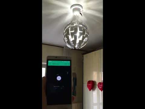 60 |
60 |
61 |
62 | ## Useful Links
63 | - My personal LinkedIn Profile;
64 | - NodeMCU Documentation;
65 | - Arduino website;
66 | - Blynk Web Page;
67 | - AccelStepper Library Website.
68 |
69 |
--------------------------------------------------------------------------------
/nodemcu/nodemcu.ino:
--------------------------------------------------------------------------------
1 | //#define BLYNK_PRINT Serial // Comment this out to disable prints and save space
2 |
3 | #include
4 | #include
5 | #include
6 | #include
7 | #include
8 | #include
9 | #include
10 |
11 |
12 | // Auth Token
13 | char auth[] = "Your_Auth_Token";
14 |
15 | // WiFi credentials
16 | char ssid[] = "Your_WiFi_SSID";
17 | char pass[] = "Your_WiFi_PSW";
18 |
19 | // Pins for Stepper Control
20 | const int sleepPin = D0;
21 | const int stepPin = D1;
22 | const int dirPin = D2;
23 |
24 | // Pin for the Relay
25 | const int relayPin = D4;
26 |
27 | // Pin for the LED
28 | const int ledPin = D6;
29 |
30 | // Max Speed and Speed of the Stepper
31 | int sp = 750;
32 | int accel = 80000;
33 |
34 | // MIN and MAX values for Lamp Gap control
35 | const int MIN = 0;
36 | const int MAX = 2400;
37 | int current = 0;
38 | int prom_pos = 0;
39 | int light = 0;
40 |
41 | // Timer
42 | SimpleTimer timer;
43 | int t = 1700;
44 |
45 | // Sectors of flash memory where to store the current position
46 | #define H_ADDRESS 500
47 | #define L_ADDRESS 501
48 | #define LIGHT_ADDRESS 502
49 |
50 | // Flag
51 | bool isFirstConnect = true;
52 | bool isOn = false;
53 | bool isReady = false;
54 |
55 | // Stepper Definition
56 | AccelStepper stepper(1, stepPin, dirPin);
57 |
58 | void readData() {
59 |
60 | // Retrieve from EEPROM the position
61 | byte high = EEPROM.read(H_ADDRESS);
62 | byte low = EEPROM.read(L_ADDRESS);
63 | prom_pos = word(high,low);
64 |
65 | }
66 |
67 | void saveData() {
68 |
69 | // Write the position to EEPROM
70 | EEPROM.write(H_ADDRESS,highByte(current));
71 | EEPROM.write(L_ADDRESS,lowByte(current));
72 | EEPROM.commit();
73 |
74 | }
75 |
76 | void moveLamp(int pos) {
77 |
78 | // Turn ON the Stepper
79 | digitalWrite(sleepPin, HIGH);
80 |
81 | if (pos == MAX) {
82 | pos = MAX-15;
83 | }
84 | else if (pos == MIN) {
85 | pos = MIN+10;
86 | }
87 | stepper.moveTo(pos);
88 | while (stepper.currentPosition() != pos) {
89 | stepper.run();
90 | }
91 |
92 | // Turn OFF the Stepper
93 | digitalWrite(sleepPin, LOW);
94 |
95 | }
96 |
97 | void moveOn() {
98 | int in = current;
99 | if (in >= MAX) {
100 | in = MAX-15;
101 | }
102 | if(current <= MAX) {
103 |
104 | if (current<=1600) {
105 | moveLamp(in+800);
106 | current = in+800;
107 | }
108 | else {
109 | moveLamp(in);
110 | current = MAX;
111 | }
112 | saveData();
113 | Blynk.virtualWrite(V0, current);
114 | }
115 | if(current == MAX) {
116 | isReady = true;
117 | }
118 | }
119 |
120 | void moveOff() {
121 |
122 | int in = current;
123 | if(in != MIN) {
124 | if(in > 800) {
125 | moveLamp(in-800);
126 | current = in-800;
127 | }
128 | else {
129 | moveLamp(MIN+10);
130 | current = MIN;
131 | }
132 | saveData();
133 | Blynk.virtualWrite(V0, current);
134 | }
135 |
136 | }
137 |
138 | void setup() {
139 |
140 | //Serial.begin(115200);
141 | EEPROM.begin(512);
142 |
143 | // Begin the Blynk session
144 | Blynk.begin(auth, ssid, pass);
145 |
146 | // Put the Stepper in SLEEP mode
147 | pinMode(sleepPin, OUTPUT);
148 | digitalWrite(sleepPin, LOW);
149 |
150 | // Turn off the Wi-Fi LED
151 | pinMode(ledPin, OUTPUT);
152 | digitalWrite(ledPin, LOW);
153 |
154 | // Turn ON and OPEN the Lamp as DEFAULT
155 | pinMode(relayPin, OUTPUT);
156 | digitalWrite(relayPin, HIGH);
157 | Blynk.virtualWrite(V1,1);
158 |
159 | if(Blynk.connected()) {
160 | // Lamp is connected -> LED ON
161 | digitalWrite(ledPin, HIGH);
162 | }
163 |
164 | // Read position from EEPROM
165 | readData();
166 |
167 | // Set correct position
168 | stepper.setCurrentPosition(prom_pos);
169 | current = prom_pos;
170 |
171 | // Set Stepper Speed and Acceleration
172 | stepper.setMaxSpeed(sp);
173 | stepper.setSpeed(sp);
174 | stepper.setAcceleration(accel);
175 |
176 | // Open the Lamp
177 | if(current != MAX) {
178 | timer.setTimer(t, moveOn, 3);
179 | }
180 |
181 | }
182 |
183 | // Sync in case of disconnection
184 | BLYNK_CONNECTED() {
185 | if (isFirstConnect) {
186 | Blynk.syncAll();
187 | isFirstConnect = false;
188 | }
189 | }
190 |
191 | // The STEPPER is connected to VIRTUAL_PIN_0 of Blynk App
192 | BLYNK_WRITE(V0) {
193 | // Allow the stepper only if the lamp is on
194 | if (isOn) {
195 | // read the value of STEPPER
196 | int input = param.asInt();
197 |
198 | moveLamp(input);
199 | current = input;
200 | saveData();
201 | }
202 | else {
203 | Blynk.virtualWrite(V0, current);
204 | }
205 | }
206 |
207 | // The BUTTON is connected to VIRTUAL_PIN_1 of Blynk App
208 | BLYNK_WRITE(V1) {
209 |
210 | // read the value of button
211 | int l = param.asInt();
212 |
213 | // Light -> ON
214 | if(l == 1) {
215 | // Turn ON
216 | digitalWrite(relayPin, HIGH);
217 |
218 | // Read position from EEPROM
219 | readData();
220 |
221 | current = prom_pos;
222 | if(current != MAX) {
223 | timer.setTimer(t, moveOn, 3);
224 | }
225 | isOn = true;
226 | }
227 |
228 | // Light -> OFF
229 | else if (l==0 && isReady){
230 | // Turn OFF
231 | digitalWrite(relayPin, LOW);
232 | isOn = false;
233 |
234 | // CLOSE the Lamp
235 | if(current != MIN) {
236 | timer.setTimer(t, moveOff, 3);
237 | }
238 |
239 | }
240 |
241 | }
242 |
243 | void loop() {
244 | Blynk.run();
245 | timer.run();
246 | }
247 |
--------------------------------------------------------------------------------