├── README.md
└── germanium_tester.ino
/README.md:
--------------------------------------------------------------------------------
1 | # arduino-uno-germanium-transistor-tester
2 |
3 | Arduino IDE C code for the Arduino Uno, using a SSD1306 OLED display and an ADS1115 16-Bit ADC
4 | 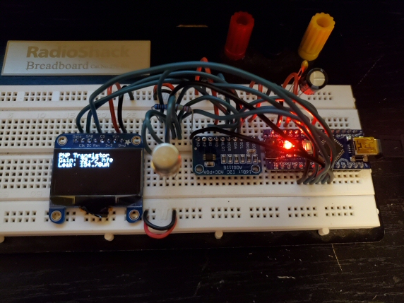 5 |
5 |
6 |
7 | I saw a post on DIY Stompboxes where someone else was attempting to do this, but I never saw them complete it
8 | I knew one of the problems was that the ADC on the ATMEGA328P is kind of limited and prone to too much noise
9 | So I found a breakout board for the ADS1115 16-Bit ADC that was available and cheap. So I opted to use that to overcome
10 | the native hardware limitations
11 |
12 | Arduino Uno Germanium Transistor Tester
13 |
14 |
15 | 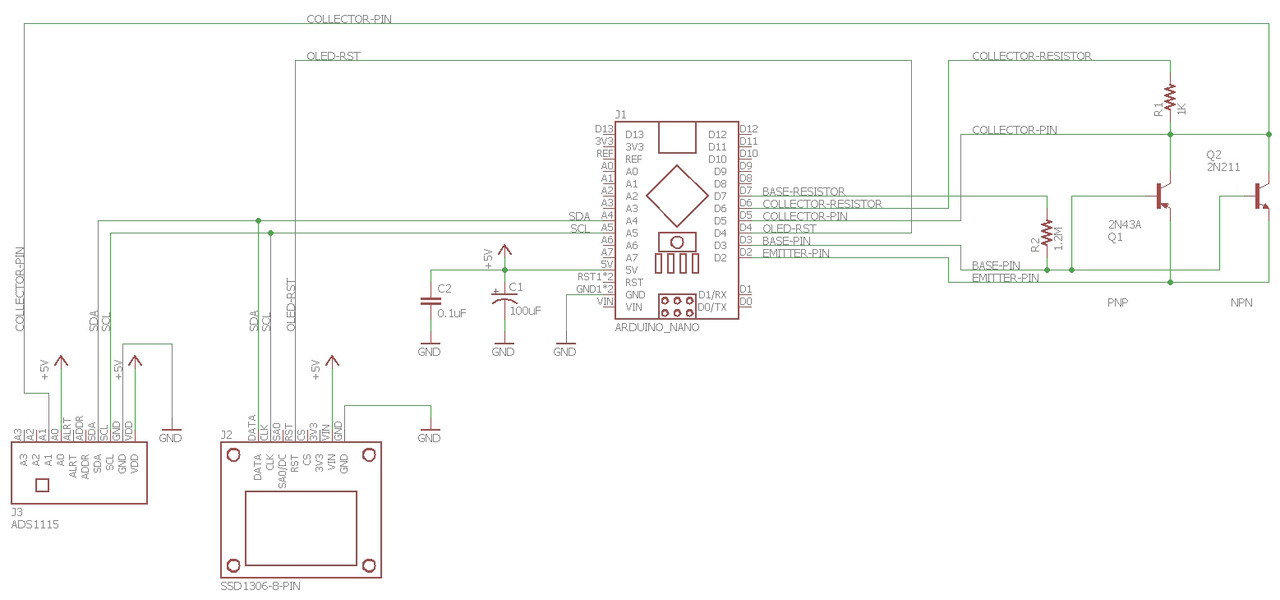 16 |
16 |
17 |
18 |
19 | Arduino Uno Germanium Transistor Tester BOM
20 |
21 | 1x 1K ohm Metal Film resistor: https://www.digikey.com/en/products/detail/stackpole-electronics-inc/RNF14FTD1K00/1706678
22 | 1x 1.2M ohm Metal Film resistor: https://www.digikey.com/en/products/detail/stackpole-electronics-inc/RNF14FTD1M21/1750283
23 | 1x 100uF Electrolytic Capacitor: https://www.digikey.com/en/products/detail/nichicon/UVR1H101MPD1TD/3438480
24 | 1x 100nF Ceramic Capacitor: https://www.digikey.com/en/products/detail/vishay-beyschlag-draloric-bc-components/K104K15X7RF5TL2/286538
25 | 1x Arduino Nano: https://www.amazon.com/ALMOCN-Compatible-ATmega328P-Controller-Arduino/dp/B08HVPMLKG/
26 | 1x I2C SSD1306 OLED Display Module: https://www.amazon.com/ALMOCN-Module-Serial-Display-SSD1306/dp/B092C8LB7B/
27 | 1x I2C ADS1115 16-Bit ADC Module: https://www.amazon.com/TeOhk-Converter-Programmable-Amplifier-Development/dp/B081CJWGHZ/
28 |
29 | Have fun!
30 |
--------------------------------------------------------------------------------
/germanium_tester.ino:
--------------------------------------------------------------------------------
1 | #include
2 | #include
3 | #include
4 | #include
5 | #include
6 |
7 | float computeMilliVolts(int16_t counts);
8 |
9 | #define SCREEN_WIDTH 128 // OLED display width, in pixels
10 | #define SCREEN_HEIGHT 64 // OLED display height, in pixels
11 | #define OLED_RESET 4 // Reset pin # (or -1 if sharing Arduino reset pin)
12 | #define SCREEN_ADDRESS 0x3D ///< See datasheet for Address; 0x3D for 128x64, 0x3C for 128x32
13 | Adafruit_SSD1306 display(SCREEN_WIDTH, SCREEN_HEIGHT, &Wire, OLED_RESET);
14 |
15 | Adafruit_ADS1115 ads; /* Use this for the 16-bit version */
16 |
17 | // These constants won't change. They're used to give names to the pins used:
18 | // constants won't change. They're used here to set pin numbers:
19 | const int emitterPin = 2; // arduino pin the emitter pin of the transistor is on
20 | const int basePin = 3; // arduino pin the base pin of the transistor is on
21 | const int collectorPin = 5; // arduino pin the collector pin of the transistor is on
22 | const int collectorResistorPin = 6; // arduino pin the collector resistor is on
23 | const int baseResistorPin = 7; // arduino pin the base resistor is on
24 |
25 | // variables will change:
26 | int collectorPinState = 0; // variable for reading the collector pin status
27 | int transistorType = 0; // Type 0 is NPN, Type 1 is PNP
28 |
29 | void setup() {
30 | int16_t adc0, adc1; // variables to hold the 16-bit ADC reading
31 | float collector_milliVolts = 0.0; // variable to hold the collector voltage in milli-volts
32 | float rail_milliVolts = 0.0; // variable to hold the rail voltage in milli-volts
33 | float leak_milliVolts = 0.0; // variable to hold leakage voltage in milli-volts
34 | float leak_uA = 0.0; // variable to hold leakage current in micro-amps
35 | float baseCurrent_uA = 0.0; // variable to hold the base current in micro-amps
36 | float gain = 0.0; // variable to hold the gain (which includes the leakage)
37 | float trueGain = 0.0; // variable to hold the true gain (subtracting leakage)
38 |
39 | // below are the results of resistance of the resistors used on this board.
40 | int16_t collector_resistor = 997; // collector resistor 1K is really 0.997K
41 | long base_resistor = 1204000; // base resistor 1.2M is really 1.204M
42 |
43 | // initialize serial communications at 9600 bps:
44 | Serial.begin(9600);
45 |
46 | // SSD1306_SWITCHCAPVCC = generate display voltage from 3.3V internally
47 | if(!display.begin(SSD1306_SWITCHCAPVCC, SCREEN_ADDRESS)) {
48 | Serial.println(F("SSD1306 allocation failed"));
49 | for(;;); // Don't proceed, loop forever
50 | }
51 |
52 | // Show initial display buffer contents on the screen --
53 | // the library initializes this with an Adafruit splash screen.
54 | display.display();
55 |
56 | if (!ads.begin()) {
57 | Serial.println("Failed to initialize ADS.");
58 | while (1);
59 | }
60 |
61 | // In this step, we will set the emitter pin to GND and the base pin
62 | // to 5 volts. So, we need to set the emitter and base pins to output
63 | // mode, so we can connect them to those power rails. The collector
64 | // pin will need to be set to input, as we will use this to see if the
65 | // transistor is an NPN or PNP germanium transistor
66 | pinMode(emitterPin, OUTPUT);
67 | pinMode(basePin, OUTPUT);
68 | pinMode(collectorPin, INPUT);
69 |
70 | digitalWrite(emitterPin, LOW); // set the emitter pin to GND
71 | digitalWrite(basePin, HIGH); // set the base pin to 5V
72 |
73 | delay(50); // wait a moment
74 |
75 | // see what the voltage is on the collector pin
76 | collectorPinState = digitalRead(collectorPin);
77 |
78 | // based off if voltage was detected on the collector pin...
79 | if (collectorPinState == HIGH) {
80 | // if we saw the voltage from the base pin jump over to the collector pin,
81 | // it's a PNP transistor (type 1)
82 | transistorType = 1;
83 | } else {
84 | // otherwise, the voltage from the base pin did not jump to the collector
85 | // pin, it's an NPN transistor (type 0)
86 | transistorType = 0;
87 |
88 | // if it is a silicon PNP transistor, this will have the same effect as an NPN
89 | // so it doesn't work.
90 | }
91 |
92 | delay(50); // wait a moment
93 |
94 | // reset the emitter and base pins and set them back to floating
95 | digitalWrite(emitterPin, LOW);
96 | pinMode(emitterPin, INPUT);
97 | digitalWrite(basePin, LOW);
98 | pinMode(basePin, INPUT);
99 |
100 | delay(50); // wait a moment
101 |
102 | // Now that we know if we have an NPN or PNP transistors, we can begin to read leak
103 | // of the transistor.
104 | // if it is a PNP transistor, emitter goes to 5V and collector goes through the
105 | // collector resistor to ground.
106 | // if it is an NPN transistor, emitter goes to ground and collector goes through the
107 | // collector resistor to 5V.
108 | if(transistorType == 1) {
109 | // Transistor is PNP
110 | pinMode(emitterPin, OUTPUT); // Set emitter pin to output so that we can...
111 | digitalWrite(emitterPin, HIGH); // Emitter goes straight to 5V
112 | pinMode(collectorResistorPin, OUTPUT);
113 | digitalWrite(collectorResistorPin, LOW); // Collector goes to ground via collector resistor
114 | } else {
115 | // Transistor is NPN
116 | pinMode(emitterPin, OUTPUT); // Set emitter pin to output so that we can...
117 | digitalWrite(emitterPin, LOW); // Emitter goes straight to ground
118 | pinMode(collectorResistorPin, OUTPUT);
119 | digitalWrite(collectorResistorPin, HIGH); // Collector goes to 5V via collector resistor
120 | }
121 |
122 | // read in voltages from the 16-bit ADC
123 | adc0 = ads.readADC_SingleEnded(0);
124 | adc1 = ads.readADC_SingleEnded(1);
125 |
126 | // rail voltage goes into ADC0 and collector voltage goes into ADC1
127 | rail_milliVolts = computeMilliVolts(adc0);
128 | collector_milliVolts = computeMilliVolts(adc1);
129 |
130 | // ohms law, V / R = I. Because we want current in uA and the volts are in milliVolts,
131 | // we need to multiply by 1000.0. This will give us the current from the base pin.
132 | // we have not applied base current at this point, but will do so later on.
133 | baseCurrent_uA = (rail_milliVolts * 1000.0) / base_resistor;
134 |
135 | if(transistorType == 1) {
136 | // Transistor is PNP
137 |
138 | // in case we get any weird jitter on the collector pin
139 | if(collector_milliVolts <= 0.1) {
140 | collector_milliVolts = 0.0;
141 | }
142 |
143 | // the leakage has caused an amount of collector voltage that we need to record and subtract
144 | // from the gain, when we get to that point.
145 | leak_milliVolts = collector_milliVolts;
146 |
147 | // ohms law, V / R = I. Because we want current in uA and the volts are in milliVolts,
148 | // we need to multiply by 1000.0. This will give us the current from the collector pin.
149 | leak_uA = (leak_milliVolts * 1000.0) / collector_resistor;
150 |
151 | // Output our findings thus far out the serial port
152 | Serial.println("PNP Transistor");
153 | Serial.print("PWR Rail: ");
154 | Serial.print(rail_milliVolts);
155 | Serial.println("mV");
156 | Serial.print("Collector: ");
157 | Serial.print(leak_milliVolts);
158 | Serial.println("mV");
159 | Serial.print("Leak: ");
160 | Serial.print(leak_uA);
161 | Serial.println("uA");
162 | Serial.print("Base: ");
163 | Serial.print(baseCurrent_uA);
164 | Serial.println("uA");
165 |
166 | delay(50); // wait a moment
167 |
168 | // now we set the base pin to output and apply a small, but pre-calculated, current over it.
169 | pinMode(baseResistorPin, OUTPUT);
170 | digitalWrite(baseResistorPin, LOW); // Base goes to ground via base resistor because it is PNP
171 |
172 | // read in voltages from the 16-bit ADC
173 | adc0 = ads.readADC_SingleEnded(0);
174 | adc1 = ads.readADC_SingleEnded(1);
175 |
176 | // rail voltage goes into ADC0 and collector voltage goes into ADC1
177 | rail_milliVolts = computeMilliVolts(adc0);
178 | collector_milliVolts = computeMilliVolts(adc1);
179 |
180 | // gain is collector-voltage / collector-resistance / base-current
181 | // so if we have 750 millivolts on the collector after applying 4uA of current to the base pin,
182 | // and we are using a 1K resistor for the collector resistor, the our gain calculation would look like this:
183 | // gain = (750mV / 1000) / 1000 ohms / (4uA / 1,000,000)
184 | // gain = 0.75V / 1000 ohms / 0.000004A
185 | // gain = 187.5
186 | gain = (collector_milliVolts / 1000.0) / collector_resistor / (baseCurrent_uA / 1000000.0);
187 |
188 | // however, this isn't the true story. The leakage voltage also goes over the collector resistor, so we must subtract
189 | // the leakage voltage from the collector voltage. So, if we had a leakage voltage of 100mV (which with a 1K collector
190 | // resistor is 100uA of leakage current), we don't actually have 750 millivolts on the collector after applying the
191 | // 4uA of current to the base pin, but rather 750mV - 100mV = 650mV, so the true gain would calculate as:
192 | // gain = (650mV / 1000) / 1000 ohms / (4uA / 1,000,000)
193 | // gain = 0.65V / 1000 ohms / 0.000004A
194 | // gain = 162.5
195 | trueGain = ((collector_milliVolts - leak_milliVolts) / 1000.0) / collector_resistor / (baseCurrent_uA / 1000000.0);
196 |
197 | // output our findings out the serial port
198 | Serial.print("Gain: ");
199 | Serial.print(gain);
200 | Serial.println(" hfe");
201 | Serial.print("True Gain: ");
202 | Serial.print(trueGain);
203 | Serial.println(" hfe");
204 |
205 | // clear the OLED display
206 | display.clearDisplay();
207 |
208 | display.setTextSize(1); // Normal 1:1 pixel scale
209 | display.setTextColor(SSD1306_WHITE); // Draw white text
210 | display.setCursor(0,0); // Start at top-left corner
211 | display.println(F("PNP Transistor")); // Start printing to screen
212 | // we will continue the rest later
213 |
214 | } else {
215 | // Transistor is NPN
216 |
217 | // the leakage has caused an amount of collector voltage that we need to record and subtract
218 | // from the gain, when we get to that point. Because the leakage is in reference to the rail
219 | // voltage, as this is an NPN transistor, we must subtract from the rail voltage to get leak
220 | // voltage
221 | leak_milliVolts = rail_milliVolts - collector_milliVolts;
222 |
223 | // in case we get any weird jitter on the collector pin
224 | if(leak_milliVolts < 0.1) {
225 | leak_milliVolts = 0.0;
226 | }
227 |
228 | // ohms law, V / R = I. Because we want current in uA and the volts are in milliVolts,
229 | // we need to multiply by 1000.0. This will give us the current from the collector pin.
230 | leak_uA = (leak_milliVolts / collector_resistor) * 1000.0;
231 |
232 | Serial.println("NPN Transistor");
233 | Serial.print("PWR Rail: ");
234 | Serial.print(rail_milliVolts);
235 | Serial.println("mV");
236 | Serial.print("Collector: ");
237 | Serial.print(leak_milliVolts);
238 | Serial.println("mV");
239 | Serial.print("Leak: ");
240 | Serial.print(leak_uA);
241 | Serial.println("uA");
242 | Serial.print("Base: ");
243 | Serial.print(baseCurrent_uA);
244 | Serial.println("uA");
245 |
246 | delay(50); // wait a moment
247 |
248 | // now we set the base pin to output and apply a small, but pre-calculated, current over it.
249 | pinMode(baseResistorPin, OUTPUT);
250 | digitalWrite(baseResistorPin, HIGH); // Base goes to 5V via base resistor because it is NPN
251 |
252 | // read in voltages from the 16-bit ADC
253 | adc0 = ads.readADC_SingleEnded(0);
254 | adc1 = ads.readADC_SingleEnded(1);
255 |
256 | // rail voltage goes into ADC0 and collector voltage goes into ADC1
257 | rail_milliVolts = computeMilliVolts(adc0);
258 | collector_milliVolts = computeMilliVolts(adc1);
259 |
260 | // because the collector voltage is in reference to the rail voltage, we have to subtract from the rail voltage
261 | // gain is collector-voltage / collector-resistance / base-current
262 | // so if we have 750 millivolts on the collector after applying 4uA of current to the base pin,
263 | // and we are using a 1K resistor for the collector resistor, the our gain calculation would look like this:
264 | // gain = (750mV / 1000) / 1000 ohms / (4uA / 1,000,000)
265 | // gain = 0.75V / 1000 ohms / 0.000004A
266 | // gain = 187.5
267 | gain = ((rail_milliVolts - collector_milliVolts) / 1000.0) / collector_resistor / (baseCurrent_uA / 1000000.0);
268 |
269 | // however, this isn't the true story. The leakage voltage also goes over the collector resistor, so we must subtract
270 | // the leakage voltage from the collector voltage. So, if we had a leakage voltage of 100mV (which with a 1K collector
271 | // resistor is 100uA of leakage current), we don't actually have 750 millivolts on the collector after applying the
272 | // 4uA of current to the base pin, but rather 750mV - 100mV = 650mV, so the true gain would calculate as:
273 | // gain = (650mV / 1000) / 1000 ohms / (4uA / 1,000,000)
274 | // gain = 0.65V / 1000 ohms / 0.000004A
275 | // gain = 162.5
276 | trueGain = (((rail_milliVolts - collector_milliVolts) - leak_milliVolts) / 1000.0) / collector_resistor / (baseCurrent_uA / 1000000.0);
277 |
278 | Serial.print("Gain: ");
279 | Serial.print(gain);
280 | Serial.println(" hfe");
281 | Serial.print("True Gain: ");
282 | Serial.print(trueGain);
283 | Serial.println(" hfe");
284 |
285 | // clear the OLED display
286 | display.clearDisplay();
287 |
288 | display.setTextSize(1); // Normal 1:1 pixel scale
289 | display.setTextColor(SSD1306_WHITE); // Draw white text
290 | display.setCursor(0,0); // Start at top-left corner
291 | display.println(F("NPN Transistor")); // Start printing to screen
292 | // we will continue the rest later
293 | }
294 |
295 | // Now display our gain and leakage findings
296 | display.print(F("Gain: "));
297 | display.print(trueGain);
298 | display.println(F(" hfe"));
299 | display.print(F("Leak: "));
300 | display.print(leak_uA);
301 | display.println(F("uA"));
302 | display.display();
303 |
304 | // Then reset all pins back to input mode
305 | pinMode(emitterPin, INPUT);
306 | pinMode(basePin, INPUT);
307 | pinMode(collectorPin, INPUT);
308 | pinMode(collectorResistorPin, INPUT);
309 | pinMode(baseResistorPin, INPUT);
310 |
311 | // So that we can then set the pins back to floating
312 | digitalWrite(emitterPin, LOW);
313 | digitalWrite(basePin, LOW);
314 | digitalWrite(collectorPin, LOW);
315 | digitalWrite(collectorResistorPin, LOW);
316 | digitalWrite(baseResistorPin, LOW);
317 | }
318 |
319 | void loop() {
320 |
321 | // wait 500 milliseconds before the next loop for the analog-to-digital
322 | // converter to settle after the last reading:
323 | delay(500);
324 | }
325 |
326 | /**************************************************************************/
327 | /*!
328 | @brief Returns true if conversion is complete, false otherwise.
329 |
330 | @param counts the ADC reading in raw counts
331 |
332 | @return the ADC reading in milli-volts
333 | */
334 | /**************************************************************************/
335 | float computeMilliVolts(int16_t counts) {
336 | uint8_t bitShift = 0; ///< bit shift amount
337 | return counts * 1000.0 * (6.144f / (32768 >> bitShift));
338 | }
339 |
--------------------------------------------------------------------------------