├── README.md
├── LICENSE
├── Unit VI - Introduction to Animation and Gaming
└── README.md
├── Unit I - Graphics Primitives and Scan Conversion Algorithm
└── README.md
├── Unit III - 2D, 3D Transformation and Projection
└── README.md
├── Unit II - Polygon, Windowing & Clipping
└── README.md
├── Unit V - Curves and Fractals
└── README.md
└── Unit IV - Light, Colour, Shading and Hidden Surfaces
└── README.md
/README.md:
--------------------------------------------------------------------------------
1 | # ✧ Computer Graphics Notes :: CG Notes | SPPU SE Comp
2 |
3 | > This Repository Contains My Notes for Computer Graphics Subject
4 |
5 | ---
6 |
7 | # ✧ Syllabus
8 |
9 | > * Unit I : Graphics Primitives and Scan Conversion Algorithm
10 | > * Unit II: Polygon, Windowing & Clipping
11 | > * Unit III: 2D, 3D Transformation and Projection
12 | > * Unit IV: Light, Colour, Shading and Hidden Surfaces
13 | > * Unit V: Curves and Fractals
14 | > * Unit VI: Introduction to Animation and Gaming
15 |
16 | ---
17 |
18 | > P.S. Done Computer Graphics
19 |
--------------------------------------------------------------------------------
/LICENSE:
--------------------------------------------------------------------------------
1 | MIT License
2 |
3 | Copyright (c) 2021 Shreyas Chavhan
4 |
5 | Permission is hereby granted, free of charge, to any person obtaining a copy
6 | of this software and associated documentation files (the "Software"), to deal
7 | in the Software without restriction, including without limitation the rights
8 | to use, copy, modify, merge, publish, distribute, sublicense, and/or sell
9 | copies of the Software, and to permit persons to whom the Software is
10 | furnished to do so, subject to the following conditions:
11 |
12 | The above copyright notice and this permission notice shall be included in all
13 | copies or substantial portions of the Software.
14 |
15 | THE SOFTWARE IS PROVIDED "AS IS", WITHOUT WARRANTY OF ANY KIND, EXPRESS OR
16 | IMPLIED, INCLUDING BUT NOT LIMITED TO THE WARRANTIES OF MERCHANTABILITY,
17 | FITNESS FOR A PARTICULAR PURPOSE AND NONINFRINGEMENT. IN NO EVENT SHALL THE
18 | AUTHORS OR COPYRIGHT HOLDERS BE LIABLE FOR ANY CLAIM, DAMAGES OR OTHER
19 | LIABILITY, WHETHER IN AN ACTION OF CONTRACT, TORT OR OTHERWISE, ARISING FROM,
20 | OUT OF OR IN CONNECTION WITH THE SOFTWARE OR THE USE OR OTHER DEALINGS IN THE
21 | SOFTWARE.
22 |
--------------------------------------------------------------------------------
/Unit VI - Introduction to Animation and Gaming/README.md:
--------------------------------------------------------------------------------
1 | # Unit VI - Introduction to Animation and Gaming
2 |
3 | ## ✧ Syllabus:
4 | > * Segment:
5 | > * Introduction
6 | > * Segment Table
7 | > * Segment Creation
8 | > * Closing
9 | > * Deleting and renaming
10 | > * Visibility.
11 | > * Animation:
12 | > * Introduction
13 | > * conventional and computer based animation
14 | > * Design of animation sequences
15 | > * Animation languages
16 | > * Key-frame
17 | > * Morphing
18 | > * Motion specification
19 | > * Gaming:
20 | > * Introduction
21 | > * Gaming platform(NVIDIA, i8060)
22 | > * Advances in gaming
23 |
24 | ---
25 |
26 | ## ✧ Segment:
27 | * Segment:
28 | > * The image is divided into small substructures called segments.
29 | > * These segments are managed using segment table.
30 | > * i.e. Part of the display file is called as a segment.
31 | > * Attributes like Visibility and image transformation are set for each segment.
32 | > * Set Visibility attribute to ON, if we want to display the object, set it OFF otherwise.
33 | > * To perform thee geometric transformation on the object, enable image transformation attribute and set appropriate parameters.
34 |
--------------------------------------------------------------------------------
/Unit I - Graphics Primitives and Scan Conversion Algorithm/README.md:
--------------------------------------------------------------------------------
1 | # Unit I: Graphics Primitives and Scan Conversion Algorithm
2 |
3 | ## Introduction to Computer Graphics
4 |
5 | ### What is CG?
6 | * CG is a way of processing, generating, manipulating, storing and displaying images.
7 | * Two types:
8 | 1. Interactive CG
9 | * It provides user a way to interact with the system.
10 | * In this type of CG, user provides an input and accordingly the output is generated.
11 | 2. Non interactive CG
12 | * Also known as passive CG.
13 | * User have no way to interact with the system.
14 |
15 |
16 | * Operations :
17 | * Geometry: how to draw and represent scene
18 | * Animation: how to make obects move or how to add dynamic content in the scene
19 | * Rendering: how to add realistic light in the scene
20 | * Imaging: Image acquisition and image editing
21 |
22 | ### Graphic Primitives
23 |
24 | * Line : collection of points along a straight path
25 | * Line Segment : It is a part of line. Curves are often represented using small line segments
26 | * Vector : A line represented using both direction and magnitude.
27 |
28 | ### Basic Terminologies
29 |
30 | * Pixel :
31 | * The smallest addressable unit of an image/screen.
32 | * Also known as pel or picture element.
33 |
34 | * Resolution:
35 | * Maximum number of pixel that can be displayed without overlap on monitor screen.
36 | * Higher the resolution better the quality.
37 | * Number of pixel defines the actual number of samples are used from real valued scene.
38 |
39 | * Aspect ratio:
40 | * the ratio of number of vertical pixels to the number of horizontal pixels required to draw a line of same length in both direction is called as aspect ratio.
41 |
42 | * Frame Buffer:
43 | * Large continuous section of computer memory is called frame buffer.
44 | * There is one bit memory for each pixel
45 | * Ideally, the size of frame buffer is same as screen resolution.
46 | * Frame buffer is known as bitmap if it uses 1 memory bit per pixel
47 | * Frame buffer is known as pixmap if it uses more than 1 memory bit per pixel
48 |
49 | ### Display Devices:
50 |
51 | * Output devices used to display information is called as Display devices.
52 |
53 | * CRT:
54 | * 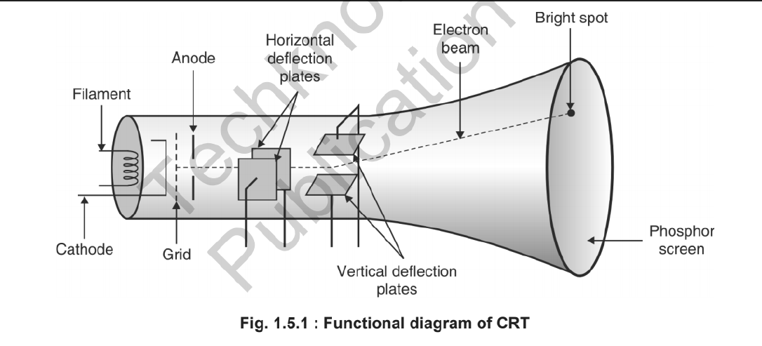
55 | * Persistence Rate:
56 | * It defines how long a pixel emits light after the CRT beam is removed.
57 | * The time it takes the emitted light to decay to 1-10th of its original intensity is called as the persistance of phosphor
58 |
59 | ---
60 |
61 | > P.S. Done
62 |
--------------------------------------------------------------------------------
/Unit III - 2D, 3D Transformation and Projection/README.md:
--------------------------------------------------------------------------------
1 | # Unit III : 2D, 3D Tranformation and Projection.
2 |
3 | ## 2D Tranformation:
4 |
5 | * 2D Tranformation:
6 | > * Repositioning and Resizing of an object is called as tranformation
7 | > * Types of Tranformation:
8 | > * Translation
9 | > * Rotation
10 | > * Scaling
11 | > * Homogenious Co-odinates
12 | > * Other Tranformation:
13 | > * shearing
14 | > * Reflection
15 |
16 |
17 | ---
18 |
19 | * Translation:
20 | > * Translation is repositioning of an object in a straight line.
21 | > * Derivation:
22 | > * 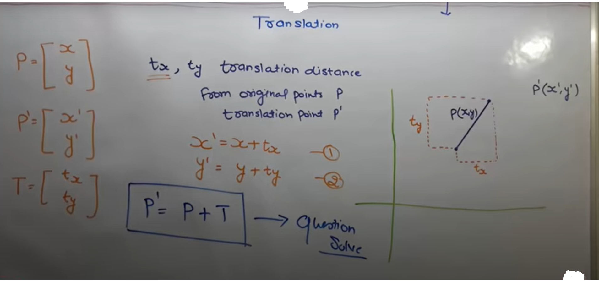
23 | > * Example Numberical:
24 | > * 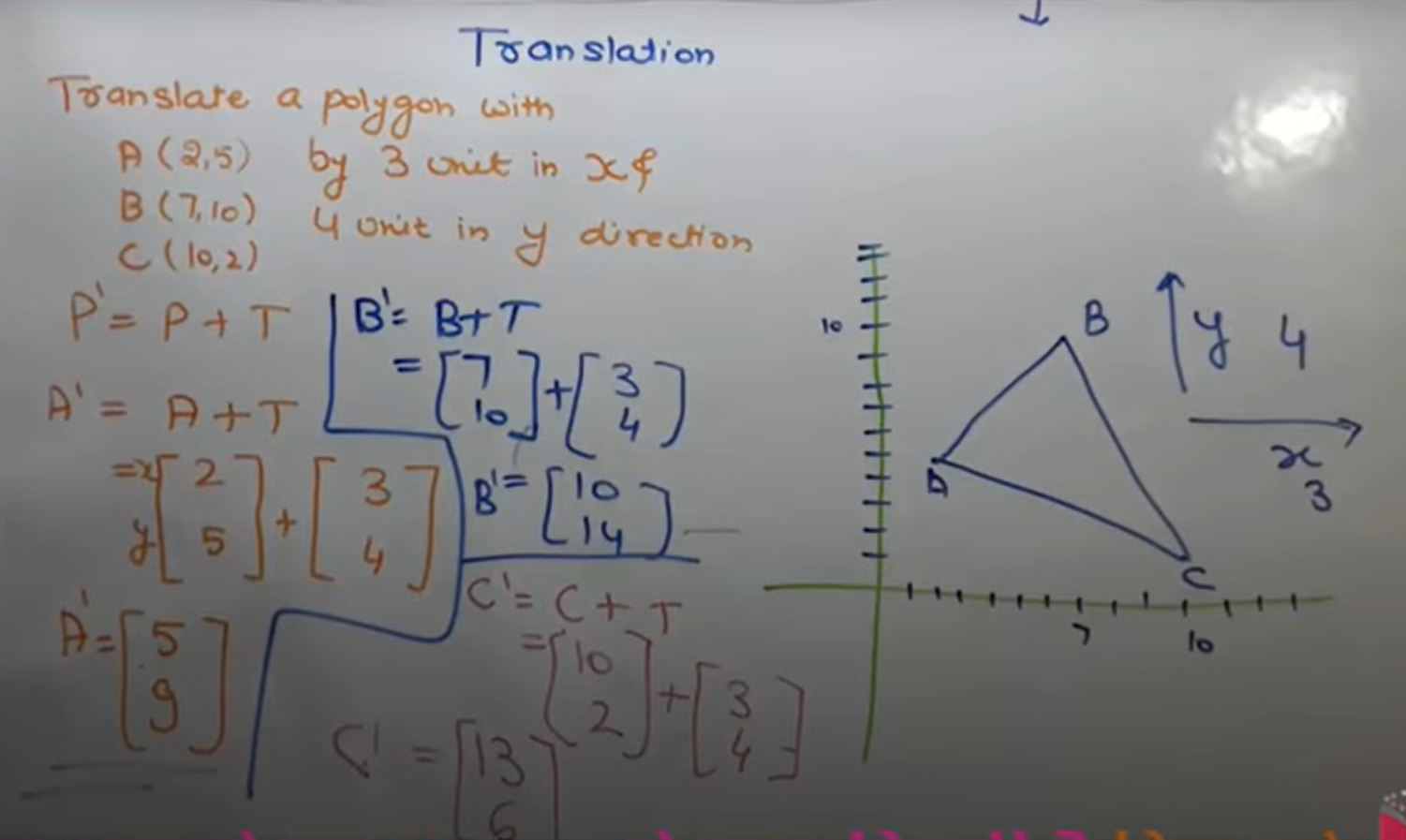
25 |
26 | ---
27 |
28 | * Rotation:
29 | > * Repositioning of an object in a circular path is called as Rotation.
30 | > * Derivation:
31 | > * 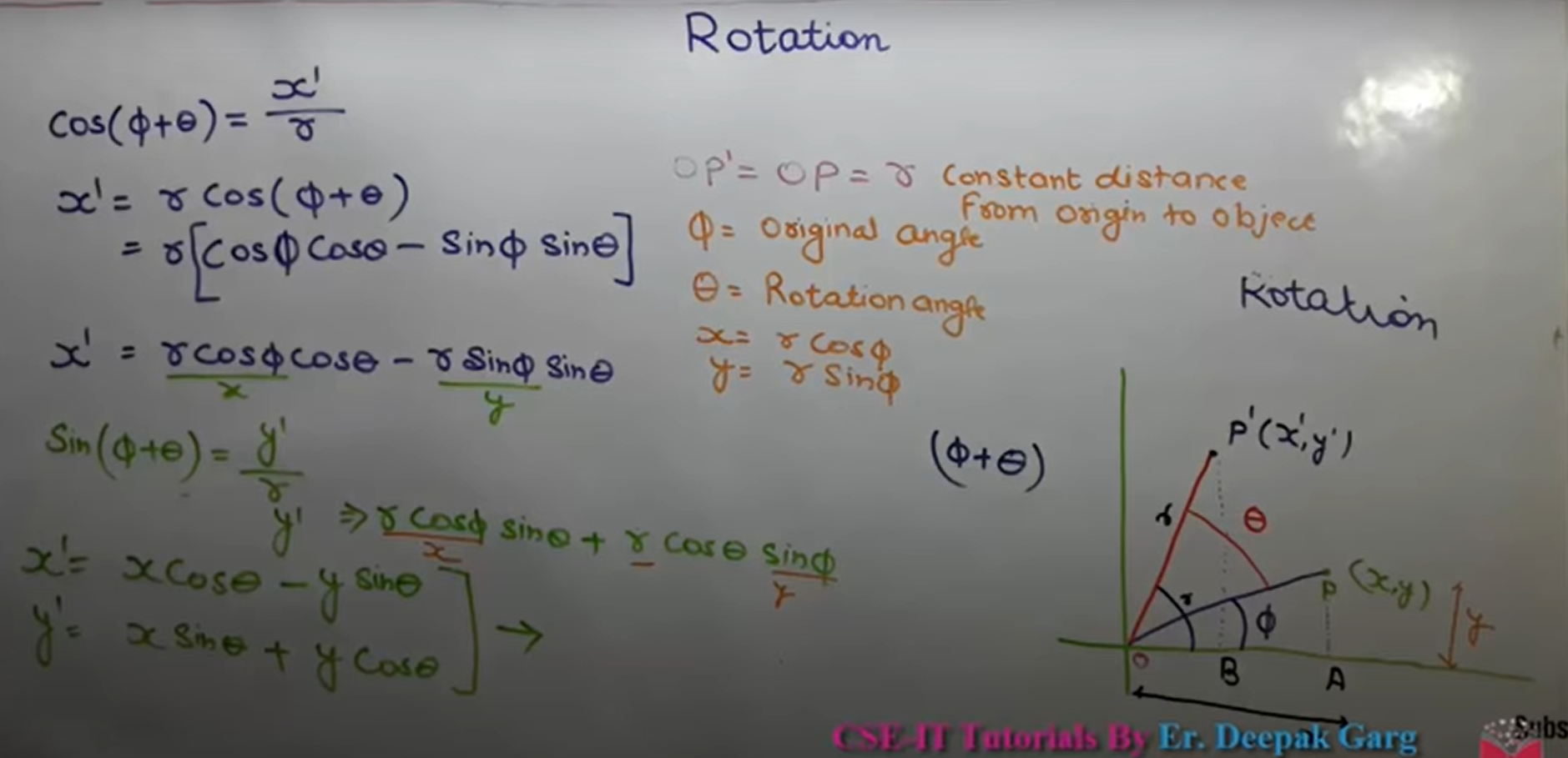
32 | > * Matrix Representation:
33 | > * 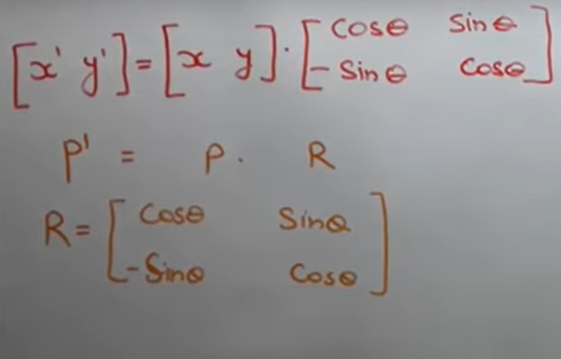
34 | > * If Anticlockwise, Rotation angle +ve
35 | > * If Clockwise, Rotation angle -ve
36 |
37 | ---
38 |
39 | * Scaling:
40 | > * Zoom-In or Zoom-out of object is called as scaling
41 | > * Scaling Factor:
42 | > * scaling in x-direction : Sx
43 | > * scaling in y-direction : Sy
44 | > * Equation:
45 | > * 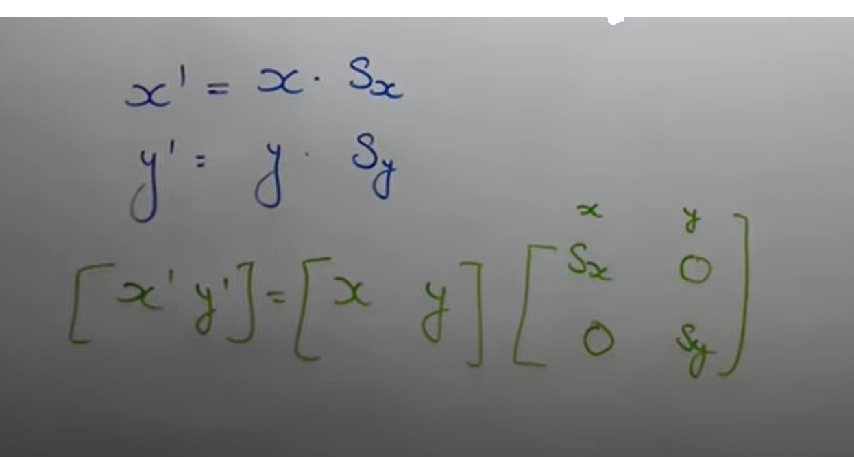
46 | > * Conditions:
47 | > * 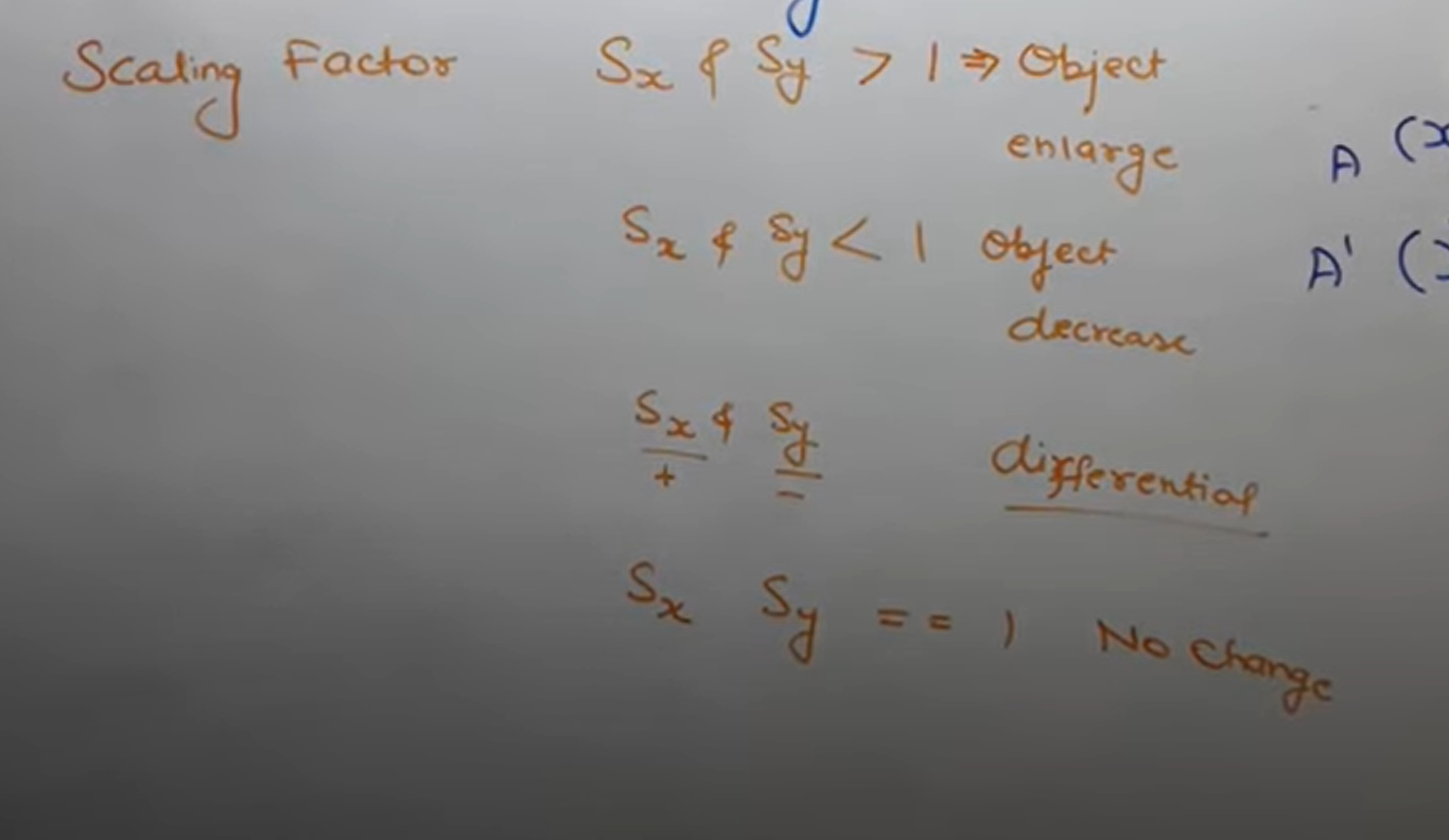
48 |
49 | ---
50 |
51 | * Homogenious Co-ordinates:
52 | > * It derives the general matrix equation that covers all the equations by translation, rotation and scaling.
53 | > * General Equation:
54 | > * 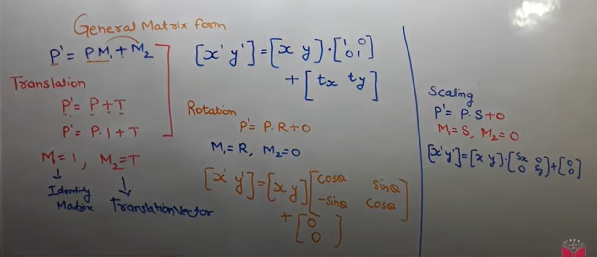
55 | > * HOmogeneous Co-ordinates (Row Major):
56 | > * 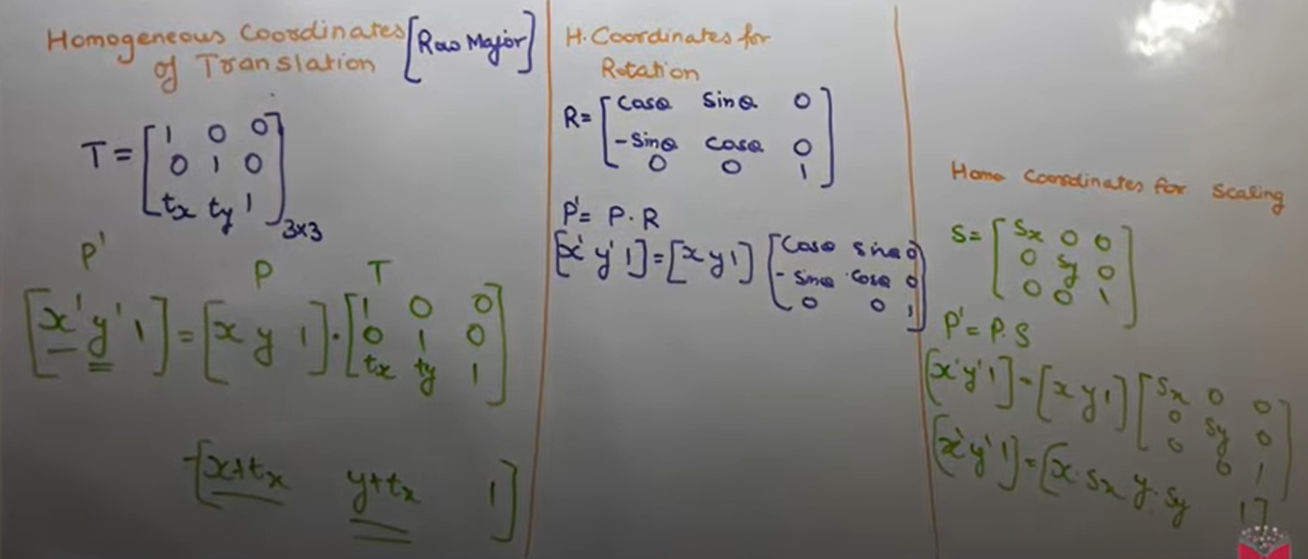
57 |
58 | ---
59 |
60 | * Rotation About Arbitrary point:
61 | > * Translate arbitrary point to origin.
62 | > * Rotate at θ angle
63 | > * Translate back at same arbitrary position.
64 | > * 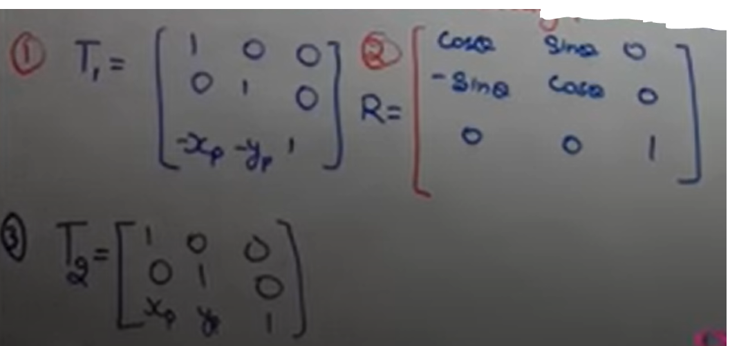
65 | > * Final Equation:
66 | > * 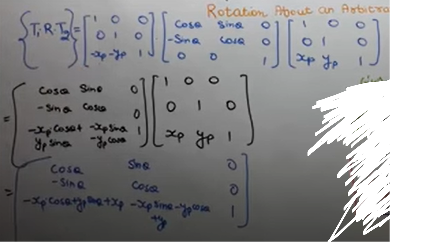
67 | >
68 |
69 | ---
70 |
71 | * Shear:
72 | > * Slanting or tilting something is called as shear
73 | > * types:
74 | > * X - shear : Only X co-ordinate change, y is preserved
75 | > * Y - shear : Only y co-ordinate change, X is preserved
76 | > * X - Shear Equation:
77 | > * 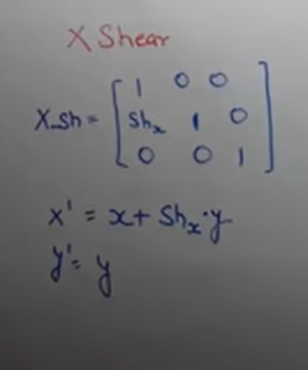
78 | > * Y - Shear Equation:
79 | > * 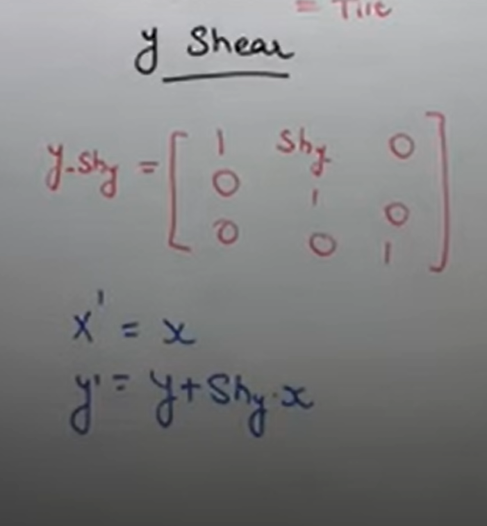
80 | >
81 | > * Shearing relative to other reference line:
82 | > * 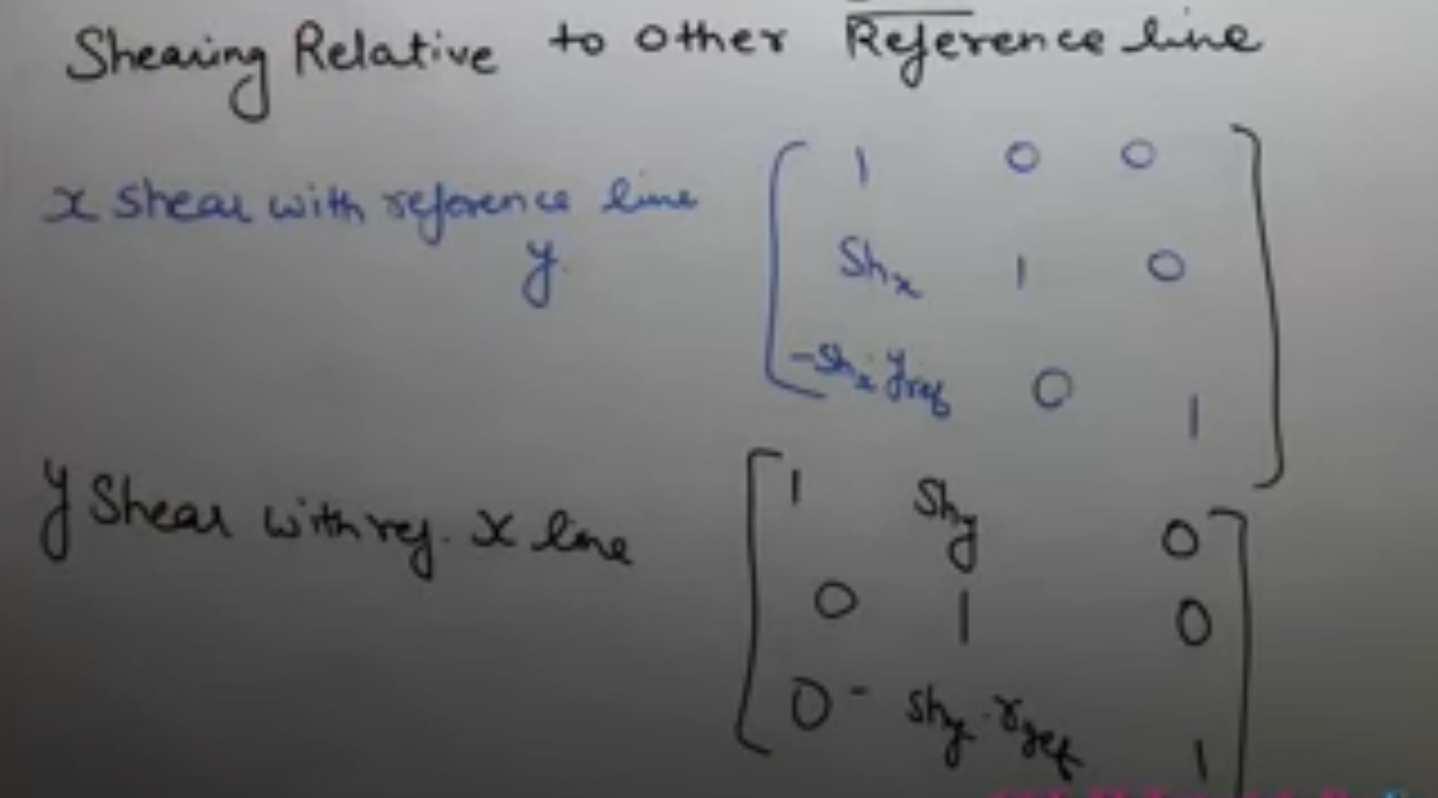
83 |
84 |
85 | ---
86 |
87 | ## 3D Tranformation:
88 |
89 | * 3D
90 | > * Dimension: defining a object in a physical spatial with minimum no. of co-ordinate is called as Dimension.
91 | > * The number of ways in which we can move in a dimension is defined as no. of dimension.
92 | > * 0D : We cannot move at all
93 | > * 1D : We can move in only one direction
94 | > * 2D : We can move in two directions
95 | > * 3D : We can move in all directions (3)
96 |
97 | ----
98 |
99 | * 3D Translation:
100 | > * Equation:
101 | > * 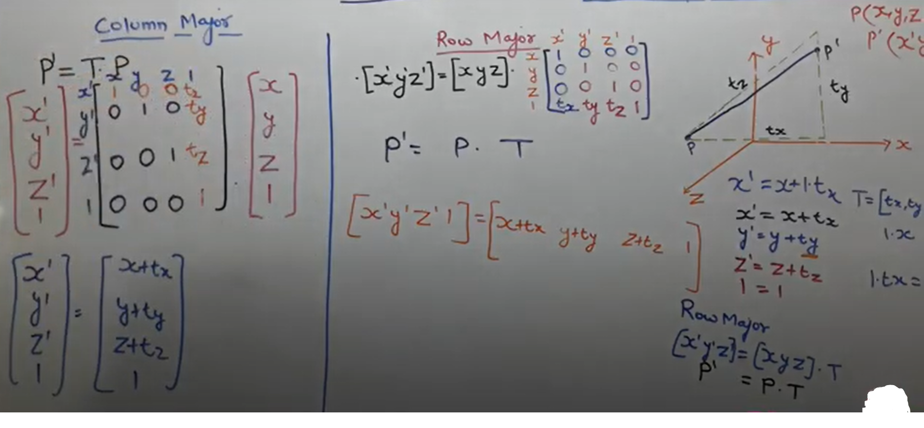
102 | >
103 |
104 | ----
105 |
106 | * 3D Scaling:
107 | > * Equation:
108 | > * 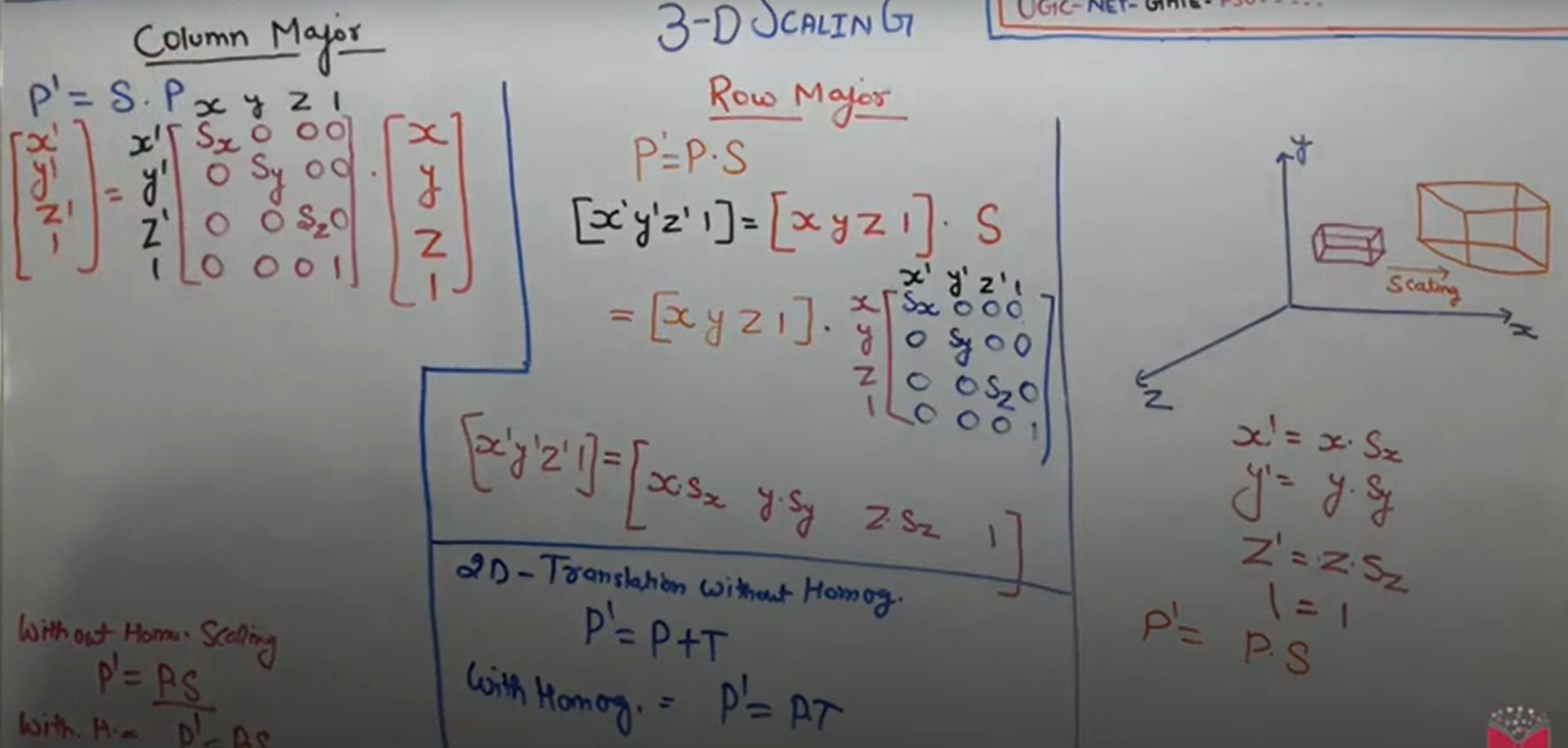
109 |
110 | ---
111 |
112 | * 3D Rotation parallel to co-ordinate axis:
113 | > * Equation z-axis:
114 | > * 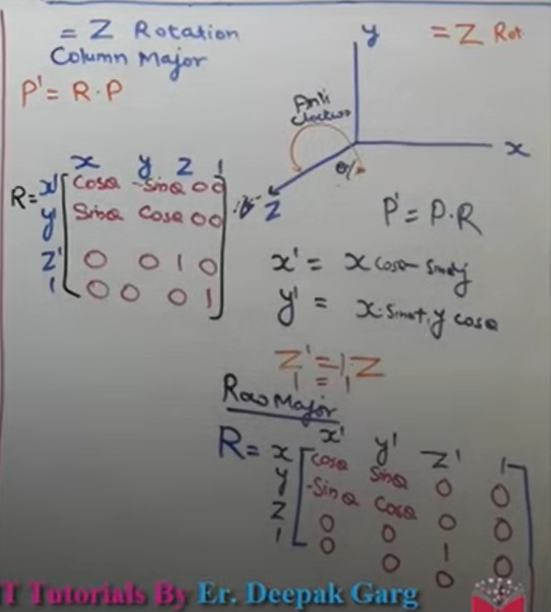
115 | > * Equation all axis:
116 | > * 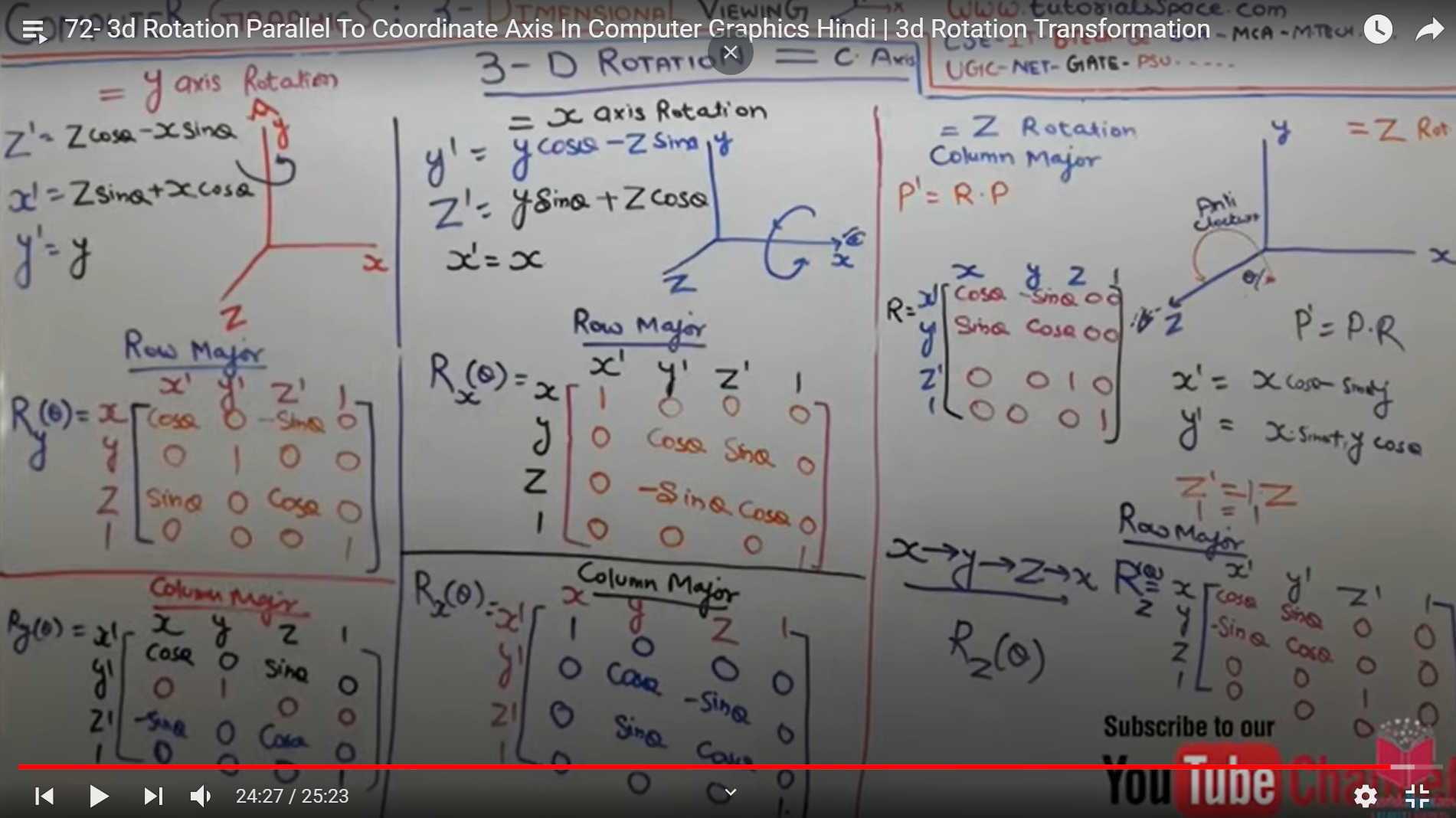
117 |
118 | ---
119 |
120 | ## Projections:
121 |
122 | * Projections:
123 | > * Projection is the process of tranforming an object representation from n-dimensional space to less than n-dimensional space.
124 | > * projection is the process of creating image on 2D plane.
125 | > * View Plane or Projectin Plane: Plane where object is projected.
126 | > * Types:
127 | > * Parallel Projection
128 | > * Perspective Projection
129 | > * 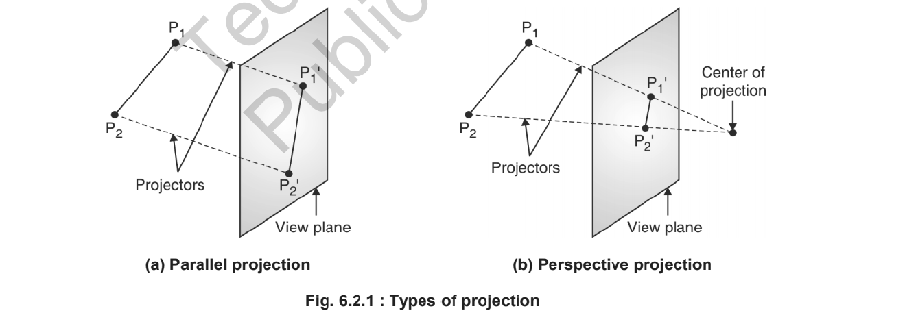
130 | > * Taxonomy of Projection:
131 | > * 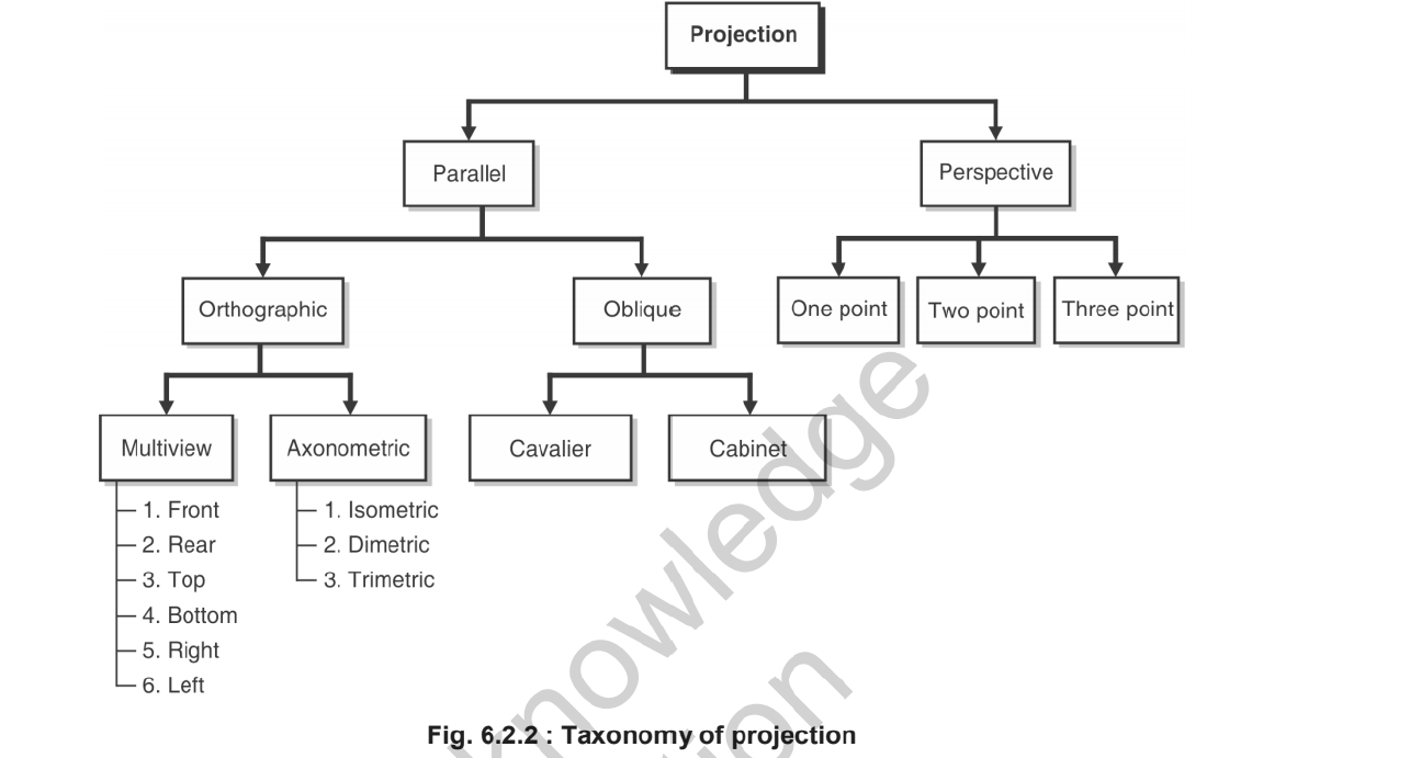
132 | >
133 | > * Rays of line is called as projector.
134 | > *
135 | ---
136 |
137 | * Parallel Projection:
138 | > * Parallel projection is achieved by passing parallel rays from the object vertices and projecting the object on view plane.
139 | > * All projection vectors are parallel to each other.
140 | > * It preserves true shape and size of the object on view plane.
141 | > * It fails to capture depth information and hence cannot produce a realistic view.
142 | > * Types:
143 | > * Orthographic Parallel projection
144 | > * Oblique parallel projection
145 | > * 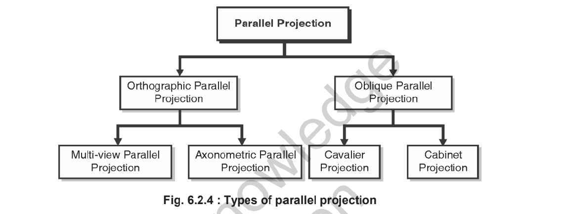
146 | > * 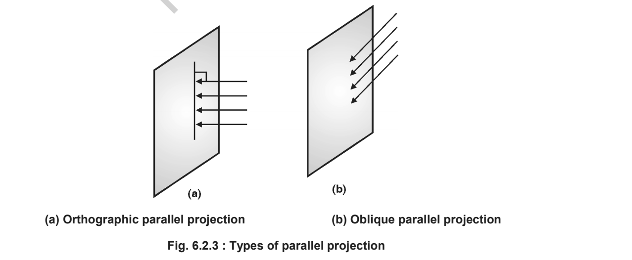
147 |
148 | ---
149 |
150 | * Orthographic Projection:
151 | > * Ortho means at Right angle.
152 | > * If projectors are perpendicular to view plane, then it is called as orthographic projection.
153 | > * Types:
154 | > * Multiview: Top view, side view, bottom view, i.e we can generate multiple type of view but they can be seen in 2Dimensional view.
155 | > * Auxinomatrix: Here we can see in all 3 dimensions
156 | > * Isometric = All angle equal - 
157 | > * Dimetric = Two angles are not equal - 
158 | > * Trimetric = Three angles are not equal. -
159 |
160 |
161 | ---
162 | * Oblique parallel Projection:
163 | > * Projectors are parallel to each other but not perpendicular to view plane.
164 | > * Types:
165 | > * Cavalier
166 | > * Keep bigger face of object
167 | > * Strike rays at any angle
168 | > * The length of image with wide length will be same and other edge length will be proportional.
169 | >
170 | > * Cabinet:
171 | > * Cabinet says if the angle is 63.40 then the wide length will look 1/2.
172 | >
173 |
174 | ---
175 |
176 | * Perspective Projection:
177 | > * Lines of projection i.e projectors will intersect and we can see the lines meeting at one point, this point i s called as center of projection/ projection reference point.
178 | > * It will give us realistic views.
179 | > * Vanishing point: Like railway track, the parallell line seems meeting at infinity, such point is called as vanishing point.
180 | > * Vanishing point types:
181 | > * 1 point : if 1 vanishing point is created then called as 1 point.
182 | > * 2 point : if 2 vanishing point is created then called as 2 point.
183 | > * 3 point : if 3 vanishing point is created then called as 3 point.
184 |
185 | ---
186 |
187 | > P.S. Done Unit III - 2D, 3D Transformation and Projection.
188 |
--------------------------------------------------------------------------------
/Unit II - Polygon, Windowing & Clipping/README.md:
--------------------------------------------------------------------------------
1 | # Unit II - Polygon, Windowing & Clipping
2 |
3 | ## Polygon:
4 | * Polygon:
5 | > * Defination: A figure or diagram drawing by joining more than two lines is called as polygon.
6 | > * Types of polygons:
7 | > * The classification of polygon is based on whre the line segment joining any two points within the polygon is going to lie.
8 | > - Convex Polygon: Line segment joining two points inside the polygon. (Line angle is less than 180^0)
9 | > - Concave polygon: Line segment joining two points outside the polygon. (at least one angle is more than 180^0 )
10 | > - Complex polygon: Polygon with intersecting edges in called as complex polygon.
11 |
12 |
13 | ---
14 |
15 | * Inside Test:
16 | > * We do inside test to check if the given pixel is inside the polygon or not.
17 | > * Even - Odd Method:
18 | > * Construct a line segment between the point in question & a known to be outside polygon.
19 | > * Count t he intersection of line with polygon boundaries.
20 | > * Inside : Odd no. of intersection
21 | > * Outside: even no. of intersection
22 | > * If intersection point in vertex: Then look at other end points of line segment.
23 | > * If points are on same side of constructed line then "even no. of intersection" for only that intersection
24 | > * If points are on different side of constructed line " then odd no. of intersection" for only that intersection.
25 | >
26 | > * Winding number Rule:
27 | > * Initialize winding no = 0
28 | > * If line crosses an edge directed bottom
29 | > * to top then add 1 to winding no.
30 | > * to top-botoom add -1 to winding number
31 | > * left to right right to left : no value
32 | > * Point outside if w.no = 0
33 | > * otherwise Inside
34 |
35 | ---
36 | ## Polygon Filling:
37 |
38 | * Polygon Filling:
39 | > * We have two methods to fill polygon,
40 | > * 1. seed fill and
41 | > * 2. scan line algorithm
42 | >
43 |
44 | ---
45 |
46 | * Seed Fill:
47 | > * We have two approaches:
48 | > * Flood fill algorithm
49 | > * Boundary fill algorithm
50 |
51 | ---
52 |
53 | * Boundary Fill Algorithm:
54 | > * We can use boundary fill, where boundary of polygon is of same colour.
55 | > * Two methods:
56 | > * 4 Connected
57 | > * 8 Connected
58 | > * 4 connected:
59 | > * Step I: It checks if pixel is already in the colour that we need as output.
60 | > * Step II: It checks if has same colour as boundary.
61 | > * If not you can fill
62 | > * Step III: Fill
63 | > * Ab boundary fill yeh kehta hai ki yeh khud toh dub gaya lekin apne passwale 4 ko leke bhi dubega.
64 | > * 4 connected means, the 4 pixels around the selected pixel will be filled
65 | > * (x,y) ---> (x+1, y), (x-1,y), (x, y+1), (x,y-1)
66 | > * 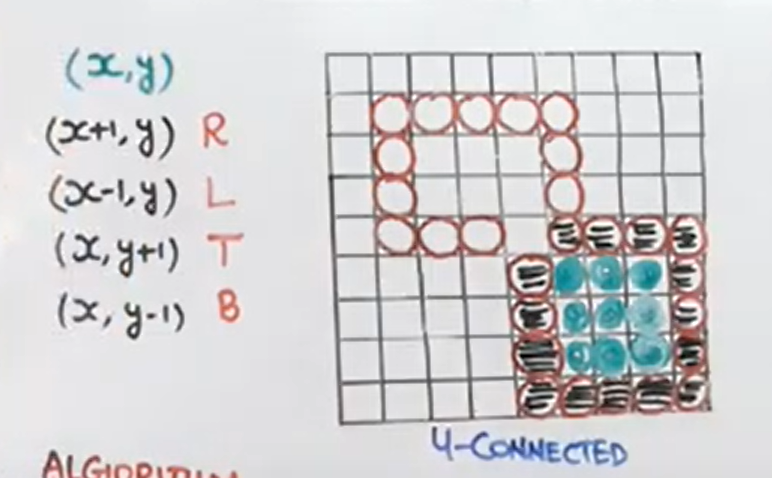
67 | > * 8 Connected:
68 | > * Same as 4-connected but also diagonal elements are considered.
69 | > * 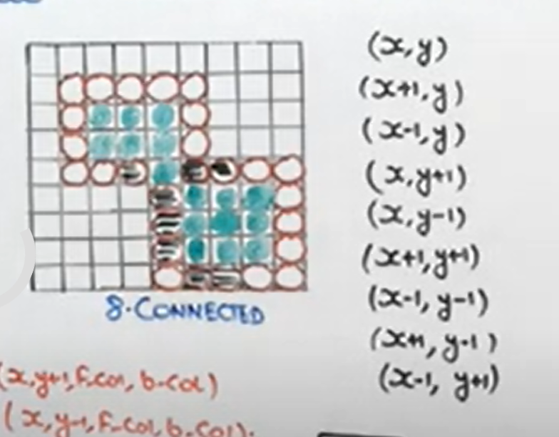
70 | > * Algorithm:
71 | > * 4 Connected:
72 | > * ```
73 | > boundary_fill(x,y,fill_colour, boundary_colour){
74 | > if(getPixel(x,y)!=boundary_colour && getPixel(x,y)!=fill_colour){
75 | > putPixel(x,y, fill_colour){
76 | > boundary_fill(x+1, y,fill_colour, boundary_colour);
77 | > boundary_fill(x-1, y,fill_colour, boundary_colour);
78 | > boundary_fill(x, y+1,fill_colour, boundary_colour);
79 | > boundary_fill(x, y-1,fill_colour, boundary_colour);
80 | > }
81 | > }
82 | > }
83 | >
84 | >
85 | > * 8 Connected:
86 | > * ```
87 | > boundary_fill(x,y,fill_colour, boundary_colour){
88 | > if(getPixel(x,y)!=boundary_colour && getPixel(x,y)!=fill_colour){
89 | > putPixel(x,y, fill_colour){
90 | > boundary_fill(x+1, y,fill_colour, boundary_colour);
91 | > boundary_fill(x-1, y,fill_colour, boundary_colour);
92 | > boundary_fill(x, y+1,fill_colour, boundary_colour);
93 | > boundary_fill(x, y-1,fill_colour, boundary_colour);
94 | > boundary_fill(x+1, y+1,fill_colour, boundary_colour);
95 | > boundary_fill(x+1, y-1,fill_colour, boundary_colour);
96 | > boundary_fill(x-1, y+1,fill_colour, boundary_colour);
97 | > boundary_fill(x-1, y-1,fill_colour, boundary_colour);
98 | > }
99 | > }
100 | > }
101 | >
102 | >
103 | ---
104 | * Flood Fill Algorithm:
105 | > * If boundary colour is different then we use flood fill.
106 | > * Same as boundary fill, 4 connected 8 connected
107 | > * Algorithm:
108 | > * ```
109 | > flood_fill(x,y, old_colour, new_colour){
110 | > if(getpixel(x,y)==old_colour){
111 | > putpixel(x,y,new_colour){
112 | > flood_fill(x+1, y, old_colour, new_colour);
113 | > flood_fill(x-1, y, old_colour, new_colour);
114 | > flood_fill(x, y+1, old_colour, new_colour);
115 | > flood_fill(x, y-1, old_colour, new_colour);
116 | >
117 | > }
118 | > }
119 | > } ```
120 | > * same for 8 connected
121 |
122 | ---
123 |
124 | * Scan Line Fill Algorithm:
125 | > * Disadvantages of Seed fill over scan line fill:
126 | > * Seed fill uses 4 to 8 connected approach
127 | > * We used to use stack there in seed fill, it can cause stack overflow.
128 | >
129 | > * What does scan line fill algorithm does:
130 | > * Scan line algorithm directly fills pixels in between the right most and left most point on the polygon.
131 | > * Steps:
132 | > * Locate the intersection points of the scan line with the polygon.
133 | > * Pairing intersection points
134 | > * move down side as per scan line & sort all pairs.
135 | > * All pairs are sorted from ymax to ymin
136 | > * Side get sorted on intersection point bases.
137 | > * Area filling starts now.
138 | > * Diagram:
139 | > * 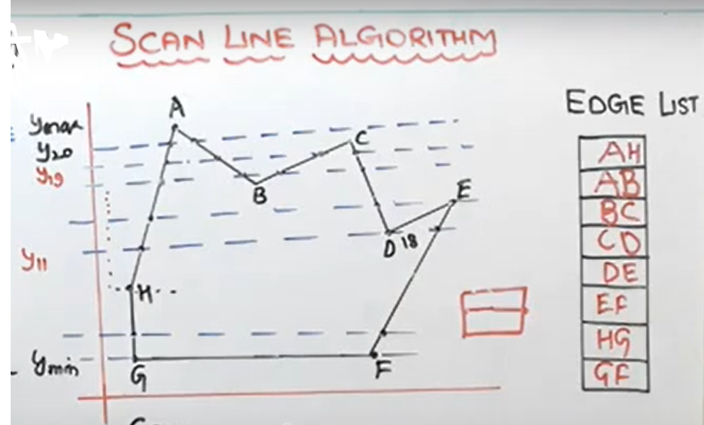
140 | >
141 | > * Coherence Property:
142 | > * Relating property of one scene to another part of scene.
143 | > * Slope of line is 'm'
144 | > * m = 
145 | > * 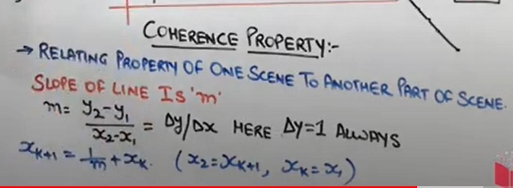
146 |
147 | ---
148 |
149 | ## Windowing and Clipping:
150 |
151 | * View Transformation:
152 | > * Windows to viewport:
153 | > * 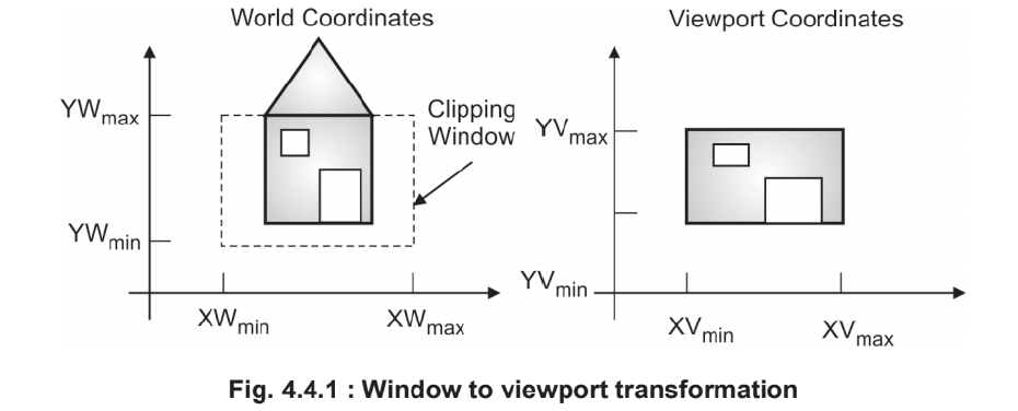
154 | > * Normalization Transformation:
155 | > * 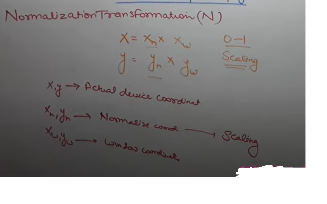
156 | > * Workstation Transformation:
157 | > * 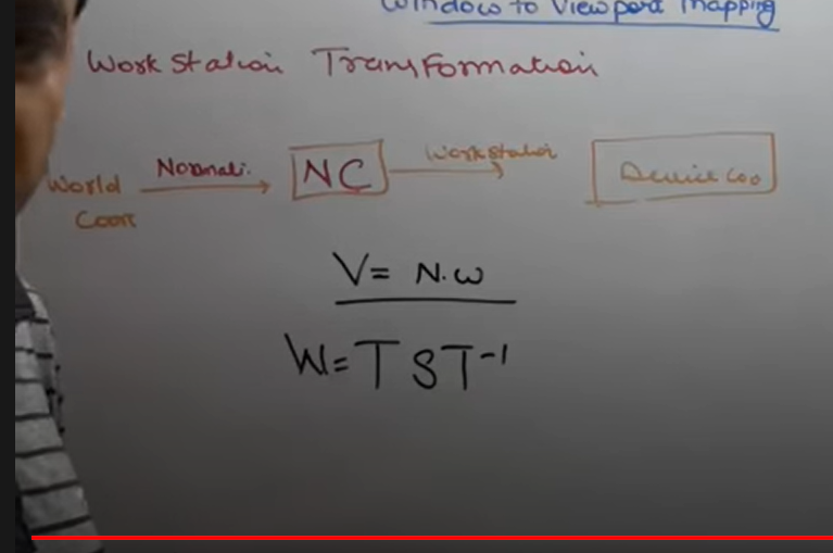
158 | >
159 |
160 | ---
161 |
162 | * 2D Clipping:
163 | > * Types of Clipping:
164 | > * Point Clipping
165 | > * Line Clipping
166 | > * Cohen-Sutherland line clipping algorithm
167 | > * Polygon Clipping
168 | > * Sutherland-hodgeman polygon clipping algo
169 | > * Curve Clipping
170 | > * Text Clipping
171 | >
172 | > * What is clipping:
173 | > * Cropping image is indirectly called as Clipping
174 | > * Clipping is a procedure by which we can select or reject a particular portion of an image in a specified region of a space.
175 | > * Clipping window: Region in which we have to show our image.
176 | >
177 | ---
178 |
179 | * Cohen - Sutherland Line Clipping Algorithm:
180 | > * He divided window in 9 parts of 4-bit region code.
181 | > * Top Bit, Bottom bit, right bit, left bit.
182 | > * Ex.
183 | > * 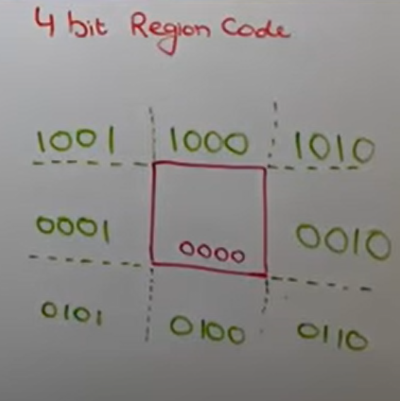
184 | > * Rules:
185 | > * If end points of a line have region code 0000, then the line is completely inside the clipping window.
186 | > * If region code of a line's end points have same 1 bit position then line is completely outside.
187 | > * If region code of both end points are not 0000 or mixup region code then perform logical AnD operation of end points, if AND is not equal to 0000, reject otherwise partially clipped.
188 | >
189 | > * Slope intercept method:
190 | > * m = (y2-y1)/(x2-x1)
191 | > * Fomulaes:
192 | > * 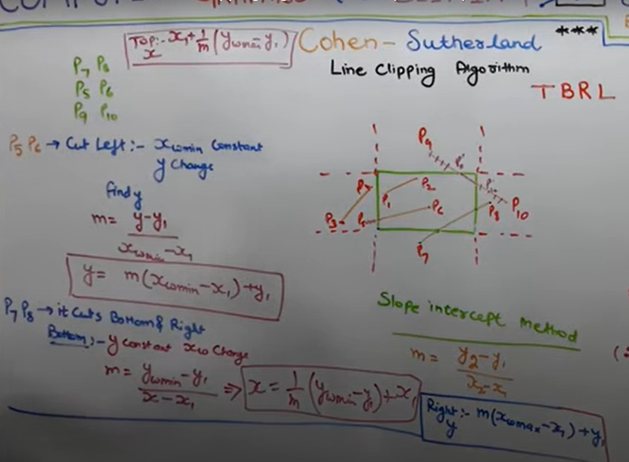
193 | > * Top:
194 | > * 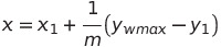
195 | > * Cut Left:
196 | > * 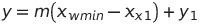
197 | > * Cuts bottom and Right:
198 | > * 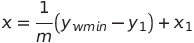
199 | > * Right:
200 | > * 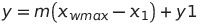
201 |
202 | ---
203 |
204 | * Sutherland Hodgeman polygon-clipping Algorithm:
205 | > * we will give computer a list of vertices(which are inside and intersect)
206 | > * 4 rules:
207 | > * 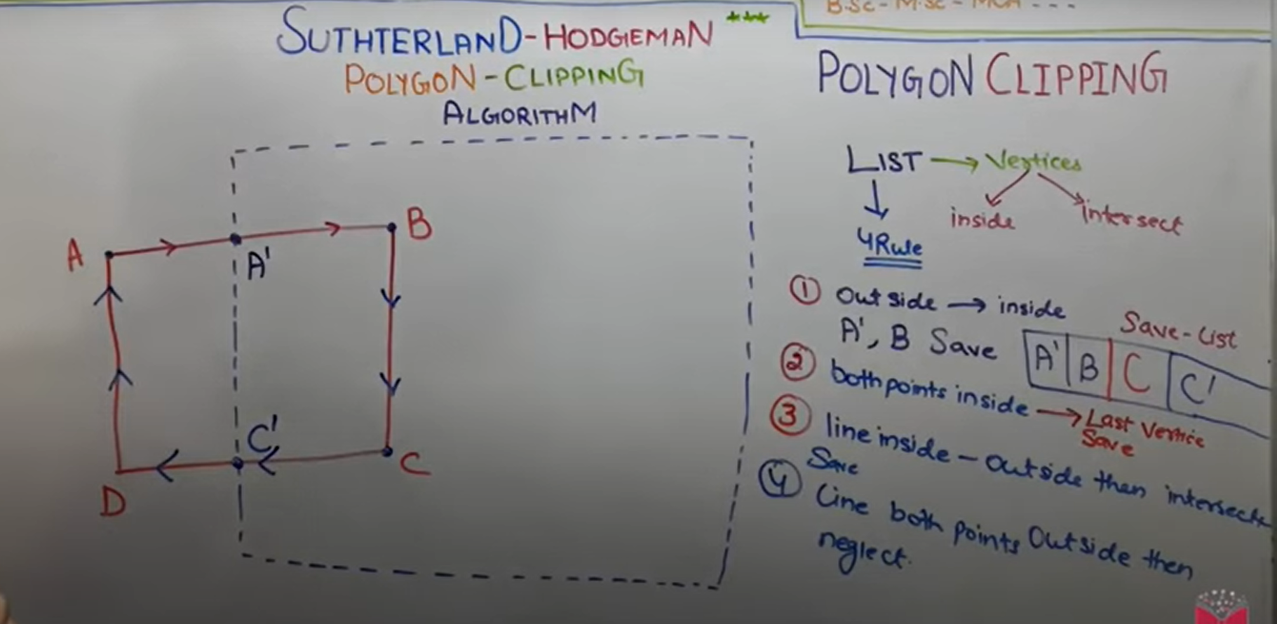
208 | > * Best result on Convex polygon.
209 | > * For concave polyhon: Extraneuos lines, at least an angle > 180^0
210 |
211 | ---
212 |
213 | * Weiler atherton polygon clipping algorithm:
214 | > * Polygon --> Subject polygon
215 | > * Clipping window --> Clip Polygon
216 | > * We will create two list here-
217 | > * Subject polygon list will be used for inserting insertion points
218 | > * Clip polygon list will be used for leaving intersection point.
219 | > * 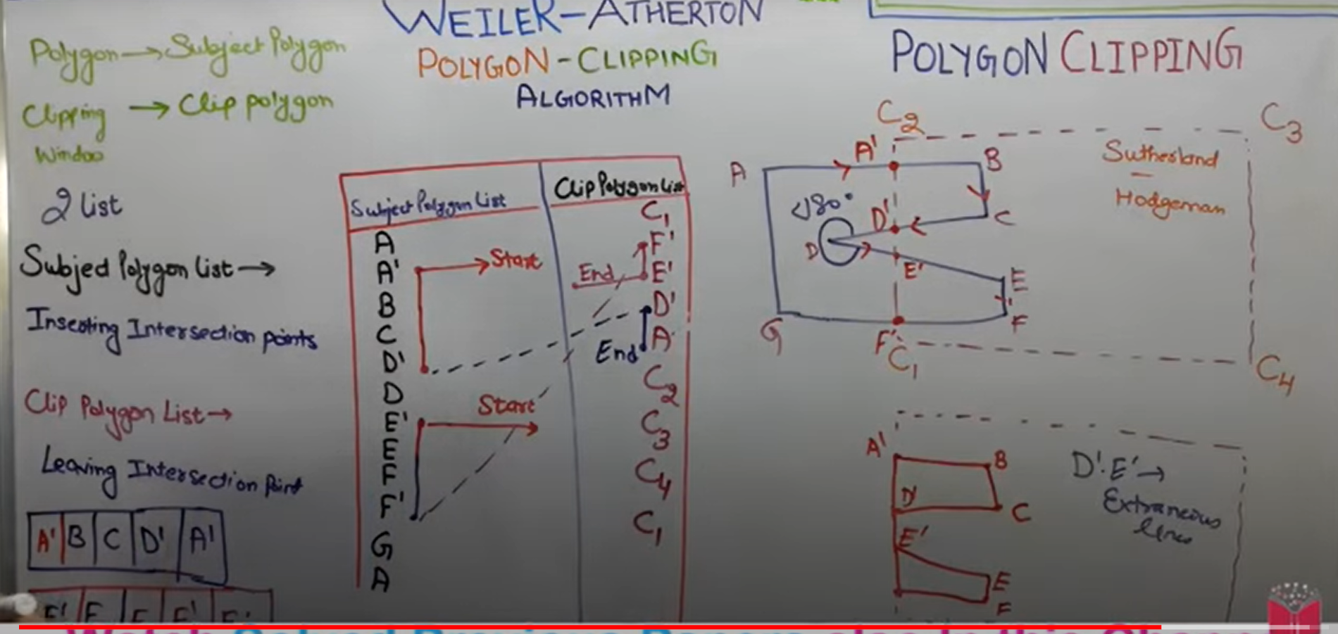
220 | > * Weiler Atherton overcomes the disadvantages of sutherland hodgeman algorithm
221 | >
222 | ---
223 |
224 | > P.S. Done Unit II - Polygon, Windowing & Clipping
225 |
--------------------------------------------------------------------------------
/Unit V - Curves and Fractals/README.md:
--------------------------------------------------------------------------------
1 | # Unit V - Curves and Fractals
2 |
3 | ## ✧ Syllabus:
4 | > * Curves:
5 | > * Introduction
6 | > * Interpolation and Approximation
7 | > * Blending Function
8 | > * B-Spline Curve
9 | > * Bezier Curve
10 | > * Fractals:
11 | > * Introduction
12 | > * Classification
13 | > * Fractal Generation:
14 | > * Snowflake
15 | > * Triadic Curve
16 | > * Hilbert curve
17 | > * Applications
18 |
19 | ---
20 |
21 | ## ✧ Curves:
22 |
23 | * **Introduction:**
24 | > * Whatever you draw continuously without lifting up pen is called as curve.
25 | > * i.e set of points joined continuously is called as curve.
26 | > * Representation:
27 | > * Explicit
28 | > * Implicit
29 | > * Parametric form
30 |
31 | ---
32 |
33 | * **Interpolation and Approximation:**
34 | > * Curve is specified by a set of control points.
35 | > * **Interpolation:**
36 | > * If the curve passes through the control points, it is called interpolation.
37 | > * **Interpolation** curves are used in animation and specifying camera motion. It is also used in digitizing the coordinates
38 | > * **Extrapolation/Approximation:**
39 | > * If the curve does not pass through the control points and approximate the shape, it is called Approximation or Extrapolation.
40 | > * Such curvevs are used to estimate the shape of the object surface.
41 | > * Example:
42 | > 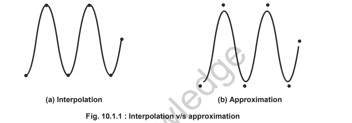
43 | > * Convex Hull:
44 | > * The curve is satisfying convex hull property if the entire curve lies within the convex hull.
45 | > * 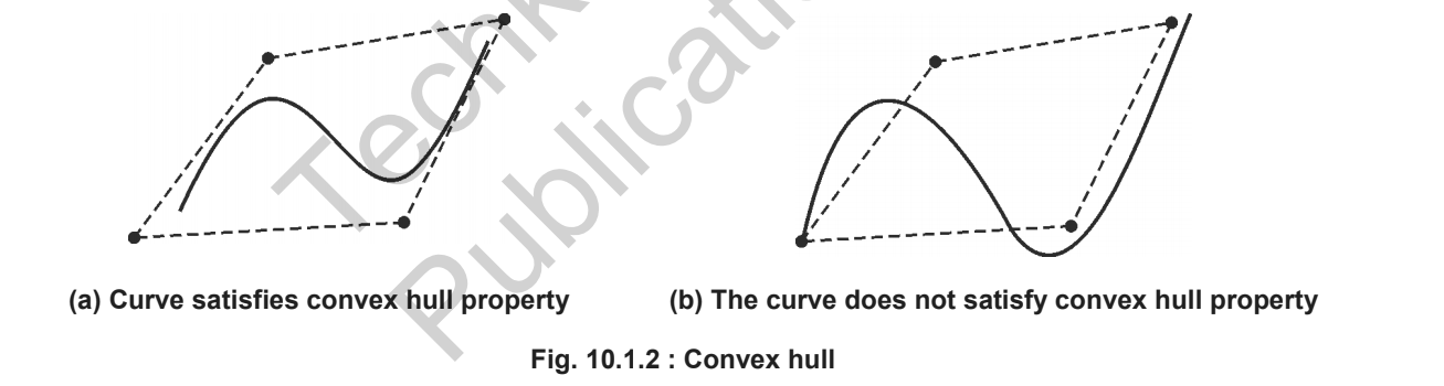
46 | > * Clipping the curve satisfying convex hull property is easy.
47 | > * Trivial acceptance and rejection conditions are easy to evaluate for them.
48 | > * If bounding box of the convex hull is inside Clipping region, no need to clip the curve. And if a bounding box is completely outside clipping window, clip the entire curve.
49 | ---
50 |
51 | * **Blending Function:**
52 | > 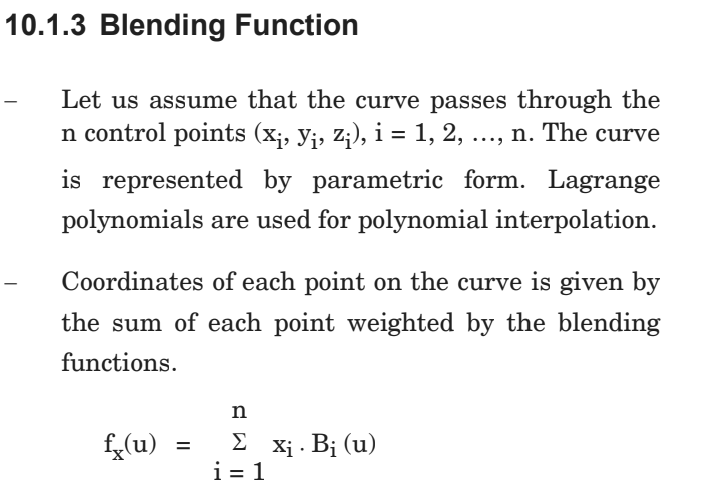
53 | > 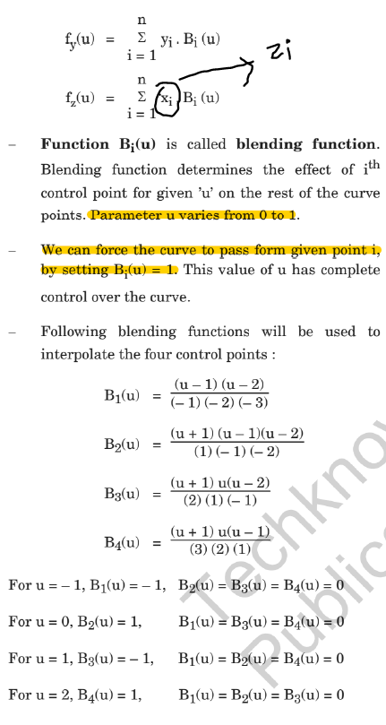
54 | > 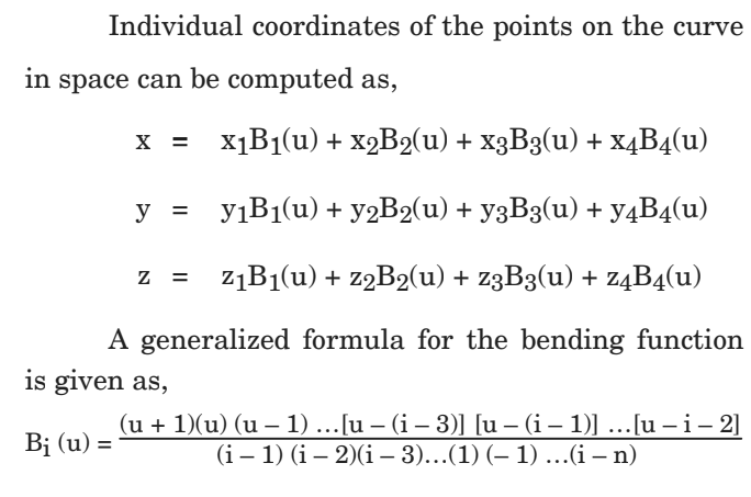
55 |
56 | ---
57 |
58 | * **Bezier Curve:**
59 | > * This is an approximate spine curve.
60 | > * With cubic polynomials, Bezier curve can approximate any number of control points.
61 | > * In Bezier curve, the degree of polynomial depends on a number of control points used to generate curve segment.
62 | > * In Bezier curve, the degree of the polynomial is always one less than a number of control points.
63 | > 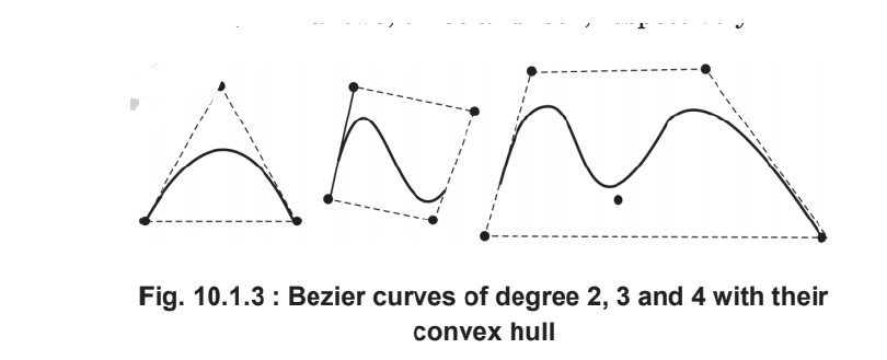
64 | > * With n + 1 control points,parametric equation of Bezier curve approximating points p0 to pn,
65 | > * 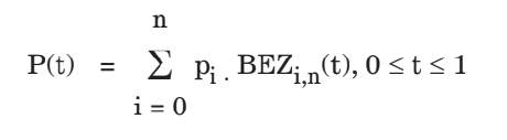
66 | > * 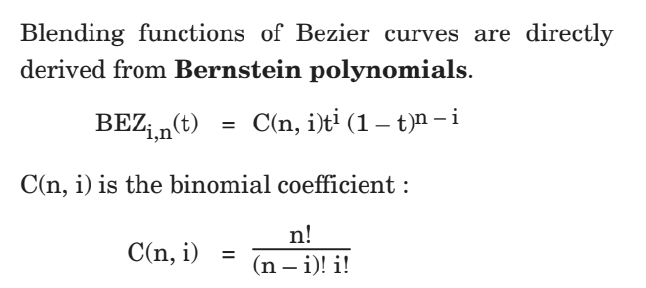
67 | > * 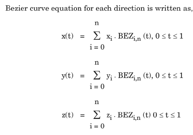
68 | > * Properties of Bezier Curves:
69 | > * Degree of the curve is one less than a number of control points
70 | > * Always interpolates first and last control points and approximates remaining two.
71 | > * The slope of the derivative at the beginning is along the line joining the first two points and slope of the derivative at the end is along the line joining last two points.
72 | > * Bezier curve always satisfies the convex hull property.
73 | > * At any parameter value t, sum all four Bezier blending function is always 1, i.e,
74 | > * 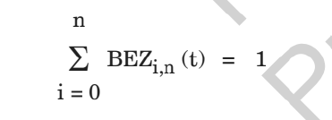
75 | > * Polynomial Smoothly follows the control points without much oscillation.
76 | > * Bezier curves do not have local control; repositioning one control point changes the entire curve.
77 | > * The curve is invariant under affine trnaformation.
78 | > * The basis functions are real.
79 | > * The curve exhibits variation diminishing property, i.e. any line intersects the Bezier curve at most as often as that line intersects the polygon interpolating control points.
80 | > * Bezier curve can fit any number of control points.
81 | > * Reversing the order of control points yield the same Bezier curve.
82 | > * **Applications of Bezier Curve:**
83 | > * 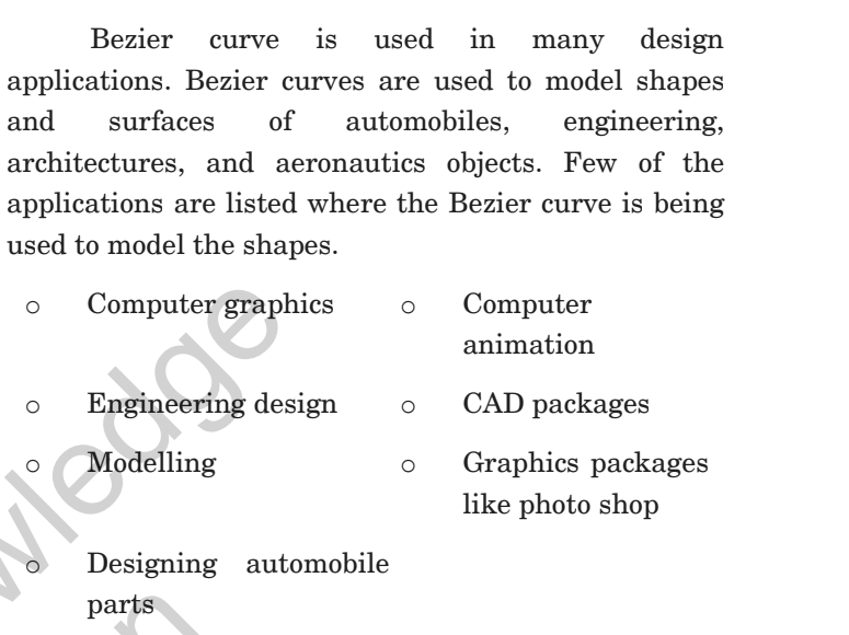
84 | > * Cubic Bezier Curves:
85 | > * Cubic Bezier curves are bridge between computation cost and smoothness.
86 | > * They are very flexible and estimate shape nicely.
87 | > * We should specify four control points to generate a cubic Bezier curve.
88 | > * Blending functions for cubic Bezier curve is derived by putting n = 3 in the equation of Bezier curve,
89 | > * 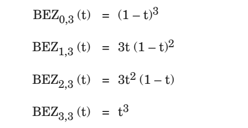
90 | > * 
91 | > * 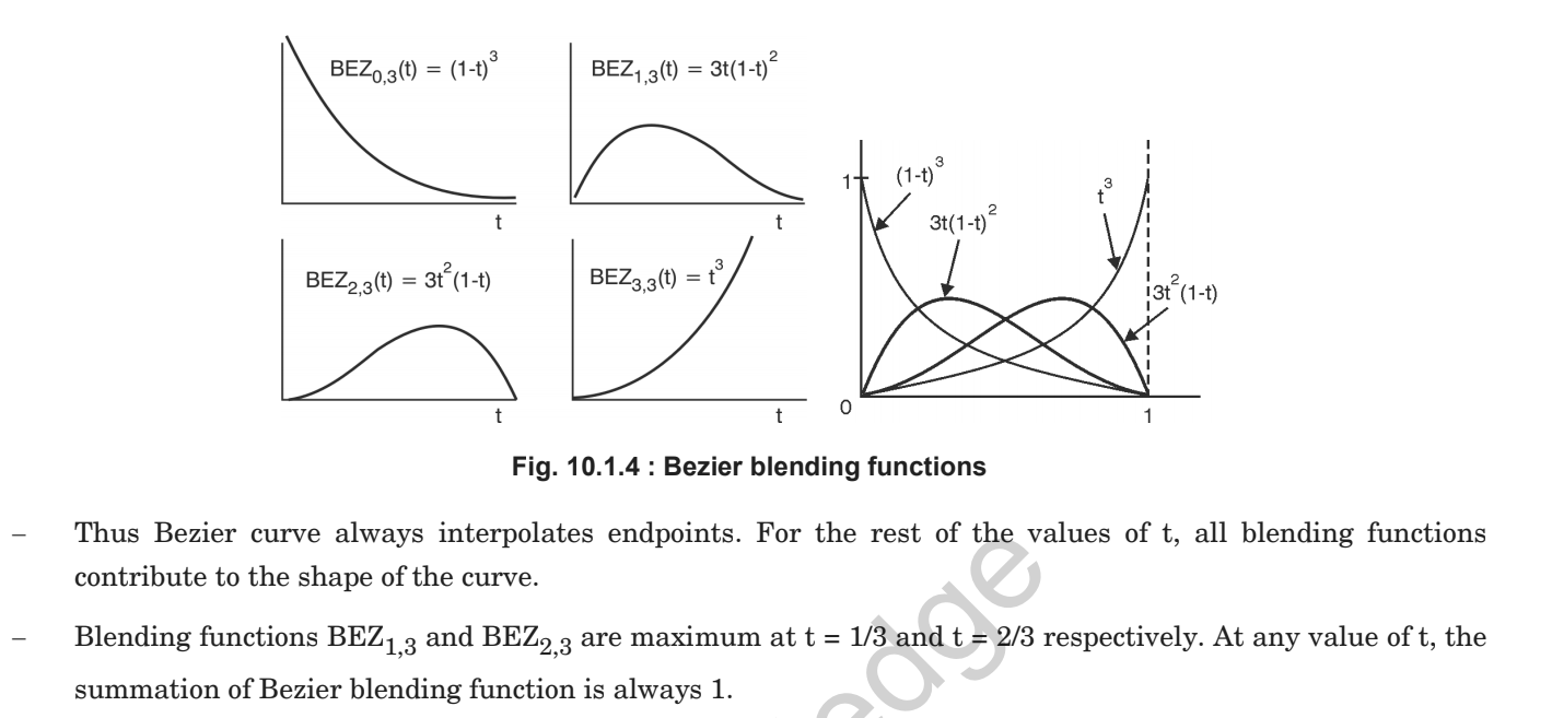
92 | > * Matrix Representation:
93 | > * 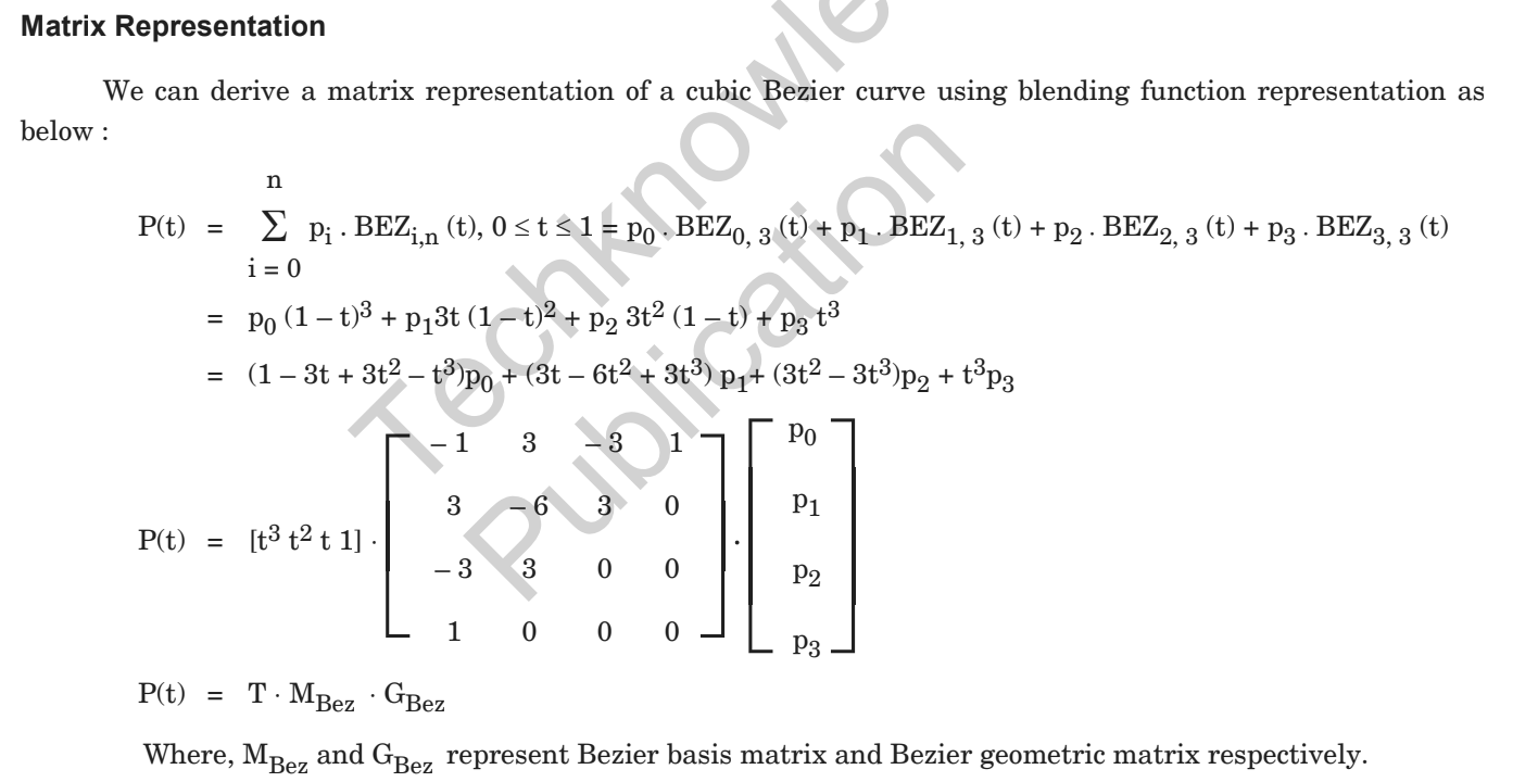
94 | > * Limitation of Bezier curve:
95 | > * 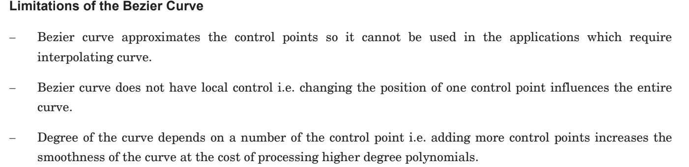
96 | > * Subdivision Method:
97 | > * 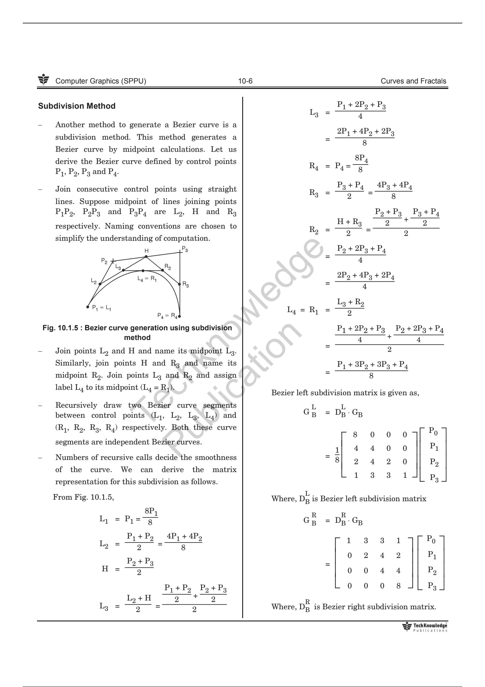
98 |
99 | ---
100 |
101 | * **B-Spline Curve:**
102 | > * 
103 | > * 
104 | > * 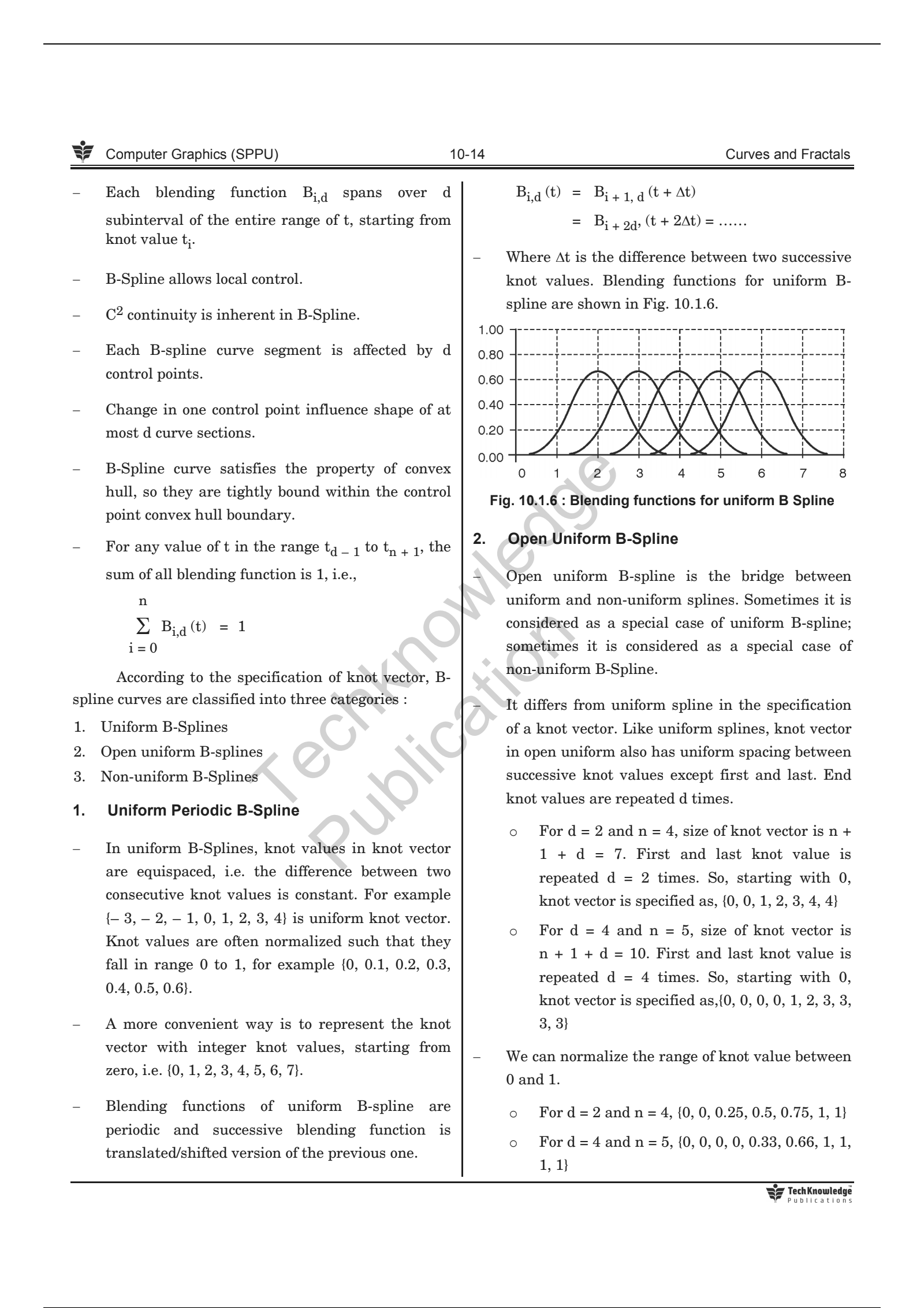
105 | > * 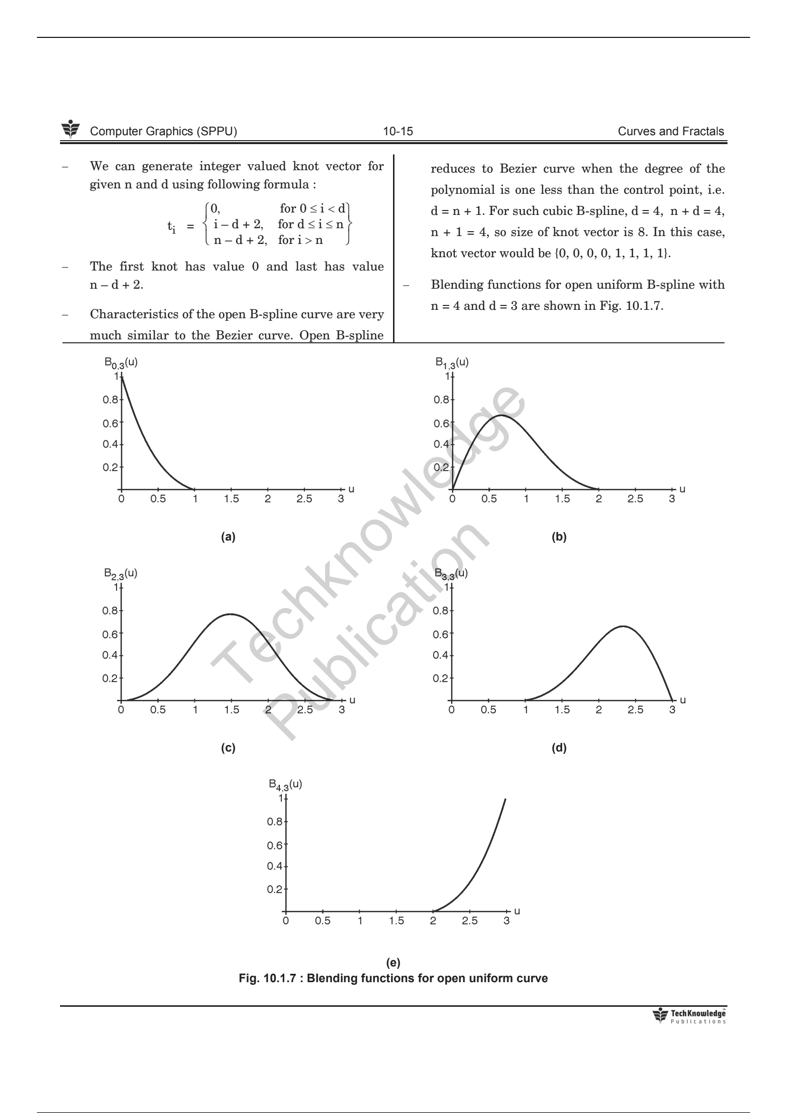
106 | > * 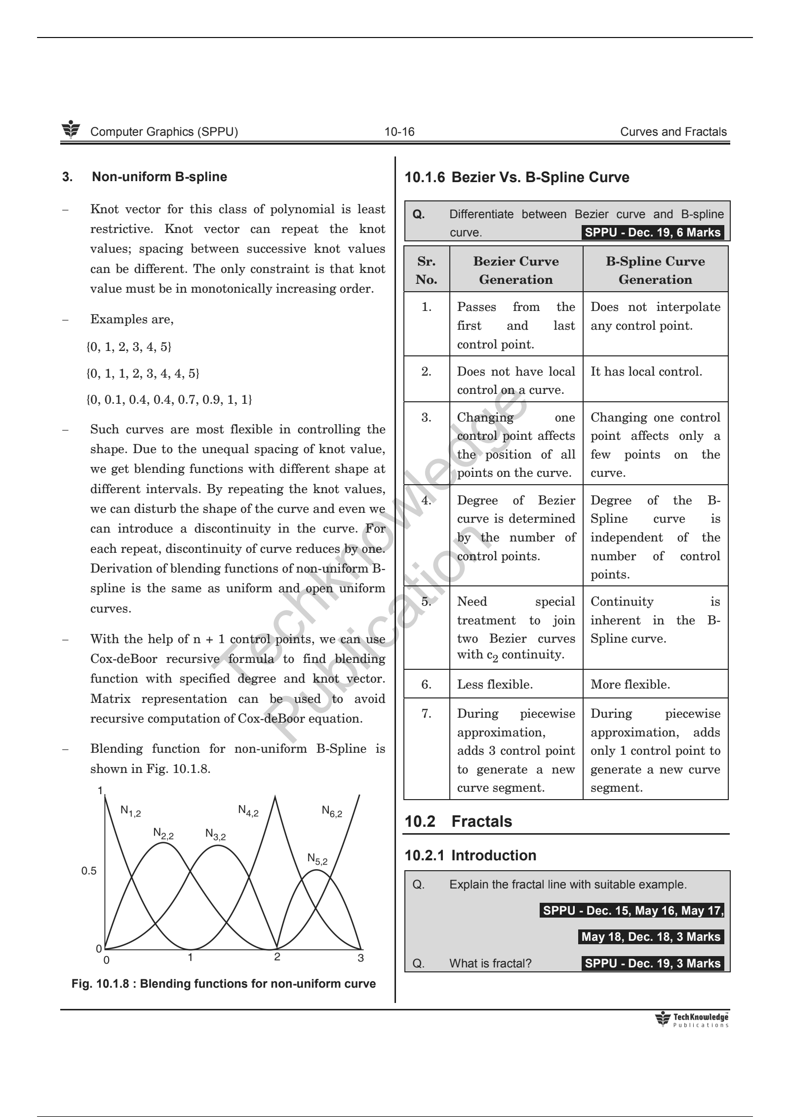
107 | >
108 |
109 | ---
110 |
111 | * **Bezier VS B-Spline Curve:**
112 | > 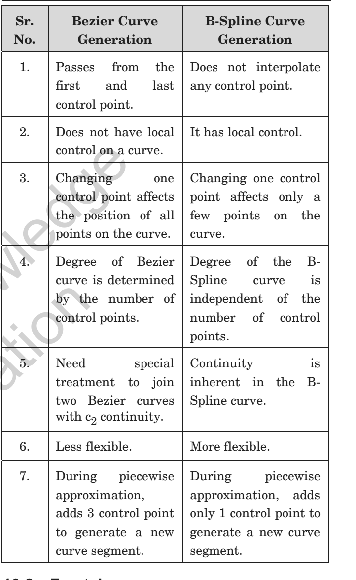
113 |
114 | ---
115 |
116 | ## ✧ Fractals:
117 |
118 | * **Fractals:**
119 | > * Fractals are infinitely complex patterns that are self similar across different scales.
120 | > * Properties:
121 | > * Infinite detail at every point.
122 | > * Self-similarity between object parts.
123 | > * Natural objects have infinite details; however, we should design a process which produces finite detail because on the computer we cannot display infinite detail.
124 | > * After certain levels of zoom in, Euclidean shapes lead to smooth drawing. While in the fractal object, if we keep zoom in, we continue to see the same detail as it appears in the original object.
125 | > * 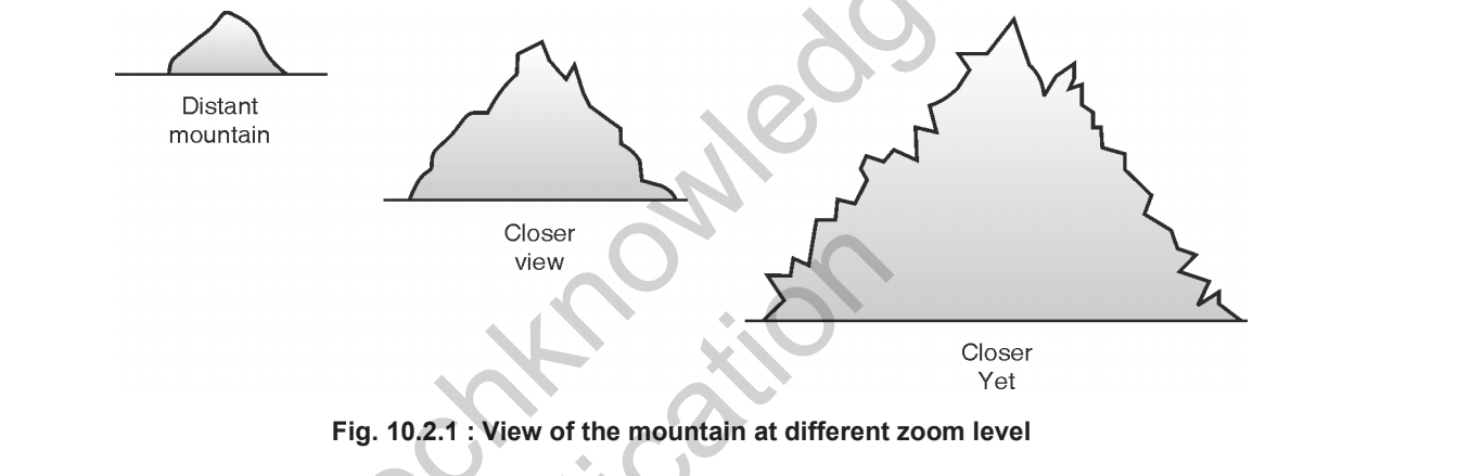
126 | > * Zoom in effect on the monitor is achieved by selecting a smaller and smaller window with the same viewport. Less and less detail is mapped to the same size as the viewport.
127 |
128 | ---
129 |
130 | * **Classification:**
131 | > * Self-similar fractals:
132 | > * Such fractal exhibits the self-similarity in shape.
133 | > * We can construct the object by applying different scaling factors to all parts or by using the same scaling factor for all.
134 | > * If we use a random scaling factor to generate the subparts, a fractal is called statistically self-similar.
135 | > * statistically self similar fractals are used to construct shapes like tree, shrubs, plants etc.
136 | > * Self-affine fractals:
137 | > * Such fractals use different scaling factors for all three directions. We can add random variation to get statistically self-affine fractals. This class of fractals is best suited to model terrain, water, clouds etc.
138 | > * Invariant fractals:
139 | > * Nonlinear transformation is applied to construct such fractals. A self-squaring function in complex space produces self-squaring fractals like Mandelbro. Self-inverse fractals are generated using the inversion procedure.
140 | > * 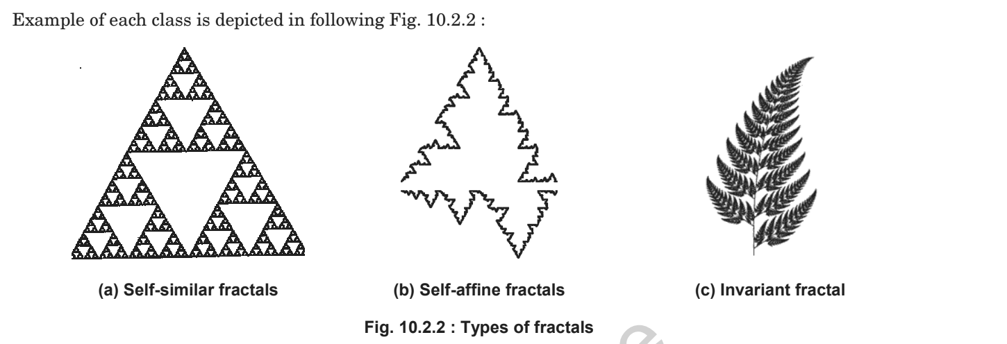
141 |
142 | ---
143 |
144 | * **Fractal generation:**
145 | > 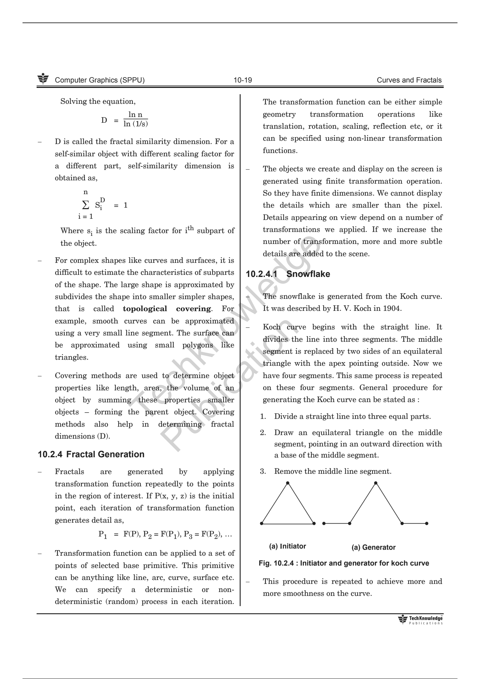
146 | > 
147 | > 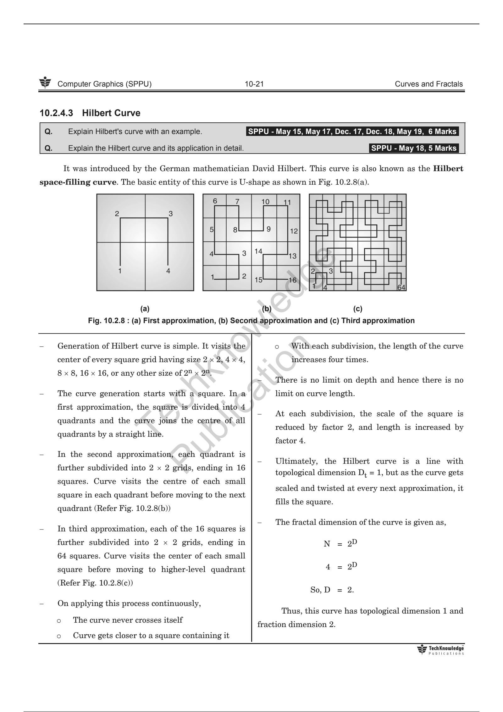
148 |
149 | ---
150 |
151 | * **Application:**
152 | > * Fractals are used to model the natural shapes. Some of the prominent application areas of fractals are listed here:
153 | > * Modelling natural structures like Geographic terrain, mountain, plant structure, clouds, vegetables, etc.
154 | > * study of the chaotic phenomenon.
155 | > * Fractal art
156 | > * Space research
157 | > * Study of convergence of iterative processes
158 | > * Engineering and architecture.
159 | > * Medical science.
160 | > * Chemical processes.
161 | > * Medical diagnostic images.
162 | > * Fluid mechanics
163 | > * Image compression
164 | > * Telecommunication
165 |
166 | ---
167 | > P.S. Done Unit V - Curves and Fractals.
168 |
--------------------------------------------------------------------------------
/Unit IV - Light, Colour, Shading and Hidden Surfaces/README.md:
--------------------------------------------------------------------------------
1 | # Unit IV - Light, Colour, Shading and Hidden Surfaces
2 |
3 | ## Syllabus:
4 | > * Colour modes:
5 | > * Properties of Light
6 | > * CIE chromaticity Diagram
7 | > * RGB
8 | > * HSV
9 | > * CMY
10 | > * Illumination Models:
11 | > * Ambient Light
12 | > * Diffuse reflection
13 | > * Specular Reflection
14 | > * and the Phong model
15 | > * Combined diffuse and Specular reflections with multiple light sources
16 | > * warn model
17 | > * Shading Algorithms:
18 | > * Halftone
19 | > * Gauraud
20 | > * Phong Shading
21 | > * Hidden Surfaces:
22 | > * Introduction
23 | > * Back face detection and removal
24 | > * Algorithms:
25 | > * Depth Buffer (z)
26 | > * Depth sorts(Painter)
27 | > * Area Subdivision(Warnock)
28 |
29 | ---
30 |
31 | ## Colour Models:
32 |
33 | * Properties of Light:
34 | > * Light is an electromagnetic wave.
35 | > * Rays having a wavelength between 400nm to 750 nm are visible.
36 | > * Light interacts with the material in four different ways.
37 | > * Emission - An object can emit the Light
38 | > * Absorption - An object can absorb the light
39 | > * Reflection - The light might bounce off the object
40 | > * Refraction/Transmission - Light might pass through the object.
41 | > * Color of object depends on a mixture of reflected frequency from the surface of the object. If the surface reflects lower frequency then object appears reddish. This dominant lower frequency decides the color and ultimately hue of the color.
42 | > * How pure color should appear is decided by the saturation.
43 | > * How bright the scene should appear is decided by the brightness.
44 | > * Purity is proportional to saturation. When hue and saturation are collectively used to describe the color, it is called chromaticity.
45 | > * Combination pairs of colors that produce neutral color like white in return is called as complementary colors.
46 | > * Ex.
47 | > * Red and Cyan
48 | > * Green and Magenta
49 | > * Blue and Yellow
50 | > * Color gamut is the set of all the visible colors to the human eye.
51 | > * In computer system, red, green and blue colors are combined with various intensity to produce all the colors.
52 | > * System supporting 24 bit per pixel can produce 17 million different colors using three basic colors red, green and blue.
53 |
54 | ---
55 |
56 | * CIE Chromaticity Diagram:
57 | > * Chromaticity diagram represents all the possible color that the human eye can perceive.
58 | > * 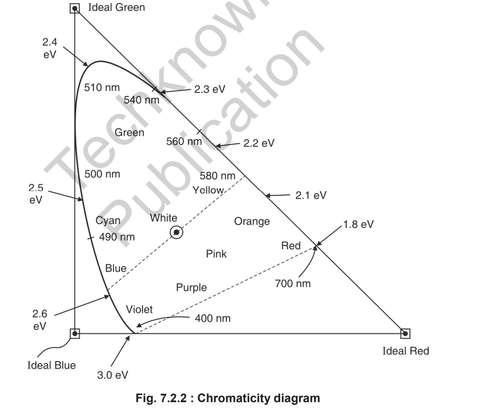
59 | >
60 | ---
61 |
62 | * Color Models:
63 | > * Color model is a system to create a wide range of colors from small set of primary colors.
64 | > * There are two types of Color modes:
65 | > * Additive
66 | > * Subtractive
67 |
68 | ---
69 |
70 | * RGB Color Model:
71 | > * It is an additive color model.
72 | > * It adds red, green and blue to produce a wide range of colors.
73 | > * Not suitable for image processing applications.
74 | > * It is a device dependent color model.
75 | > * Different devices reproduce the same RGB value differently.
76 | > * We can define this color model as a unit cube with R, G, B as its three axes.
77 | > * Zero intensity of all three component produce black color and full intensity of them produce the white color.
78 | > * An equal proportion of all three colors between zero to one produce grey shade (diagonal line joining origin and opposite cube corner.)
79 | > * 
80 | > * When anyone component has a dominant intensity, the color is a hue of primary color, and when two components have the same dominant intensity, then the color is a hue of a secondary color. A secondary color is formed by the sum of two primary colors of equal intensity.
81 | > * When primary and its complementary secondary color are added together, the result is white.
82 | > * ex. the complement of red is cyan, the complement of green is magenta and the complement of green is yellow.
83 | > * RGB is an additive color model and any color C can be obtained by addition of R, G and B.
84 | > * C = RR + GG + BB
85 | > * 
86 | > * 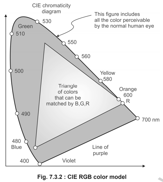
87 | >
88 | ---
89 |
90 | * HSV Color Model:
91 | > * H, S and V stand for Hue, Saturation and Value, repectively.
92 | > * Hue defines the color
93 | > * Saturation defines the purity of color
94 | > * Value defines the intensity.
95 | > * RGB and CMY are defined over cubic space
96 | > * HSV is defined over hexagon or cone shape.
97 |
98 | ---
99 |
100 | * CMY color model:
101 | > * CMY color model is subtractive color model.
102 | > * C - Cyan, M - Magenta, Y - Yellow
103 | > * 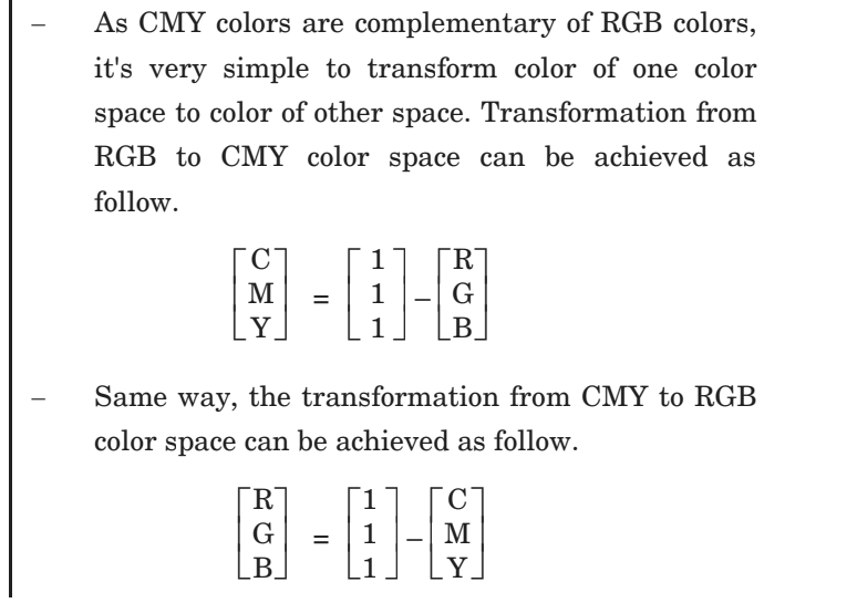
104 |
105 | ---
106 |
107 | * Difference between RGB and HSV color model:
108 | > * 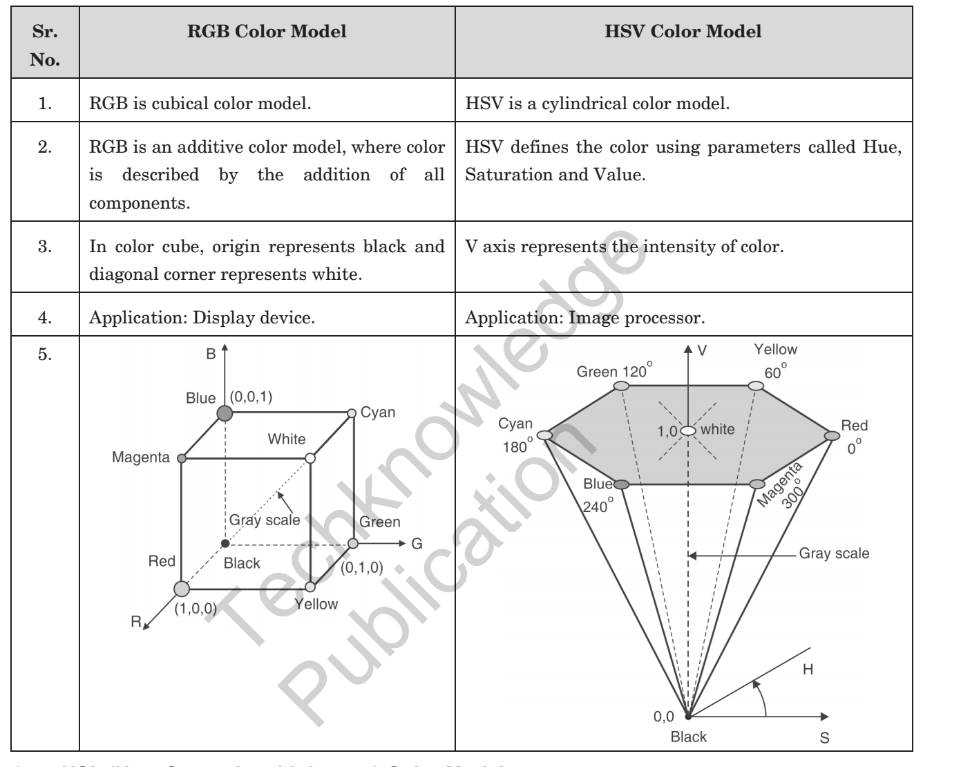
109 |
110 | ---
111 |
112 | ## Illumination Model:
113 |
114 | * Illumination Model:
115 | > * Lighting models that are used to calculate intensity at every pixel in the scene is also known as Illumination model.
116 | > * Light Source:
117 | > * Light emitting source
118 | > * Surface that reflects light can also act as light source.
119 |
120 | * Ambient Light:
121 | > * Even if the object is not directly exposed to the light source, due to reflected rays from the other surfaces, it would be still visible. Such light is called as ambient light.
122 | > * Ambient light is constant for all the surfaces and it scatters equally in all direction.
123 | > * Objects illuminated using ambient Illumination model appears as a monochromatic, silhouette, unless the polygon facets of objects are given different shades.
124 | > * If we assume that the ambient light reflected from all surfaces are the same and in all directions, then the illumination model equation would be,
125 | > * 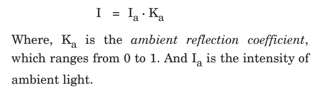
126 |
127 | ---
128 | * Diffuse and Specular Reflection
129 | > * Diffuse Reflection:
130 | > * Equal reflection of light in all direction from surface is called as diffuse reflection.
131 | > * 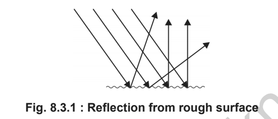
132 | > * Specular Reflection:
133 | > * Reflection in a particular direction only is know as specular reflection.
134 | > * 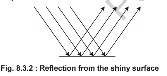
135 | > * 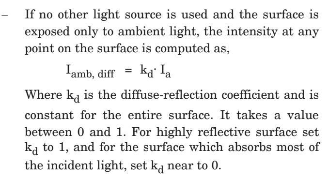
136 | > * Ideal diffuse Reflector or Lambertian reflectors:
137 | > * If diffuse reflection scattered from the surface is equal in all direction, independent of viewing directions, such surfaces are called ideal diffuse reflector or Lambertian reflectors, since the radiated light energy from any surface is governed by Lambert's cosine law.
138 |
139 | ---
140 |
141 | * Specular Reflection and Phong Model:
142 | > * Specular Reflection:
143 | > * Reflection in a particular direction only is know as specular reflection.
144 | > * 
145 | > * 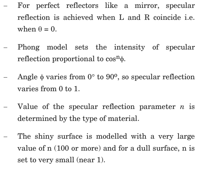
146 | > * 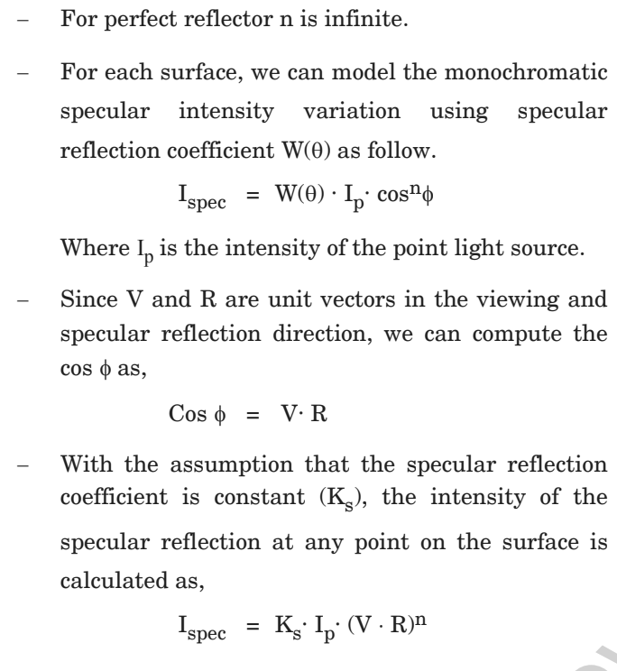
147 |
148 | ---
149 | * Combined Diffuse and Specular Reflections with Multiple Light Sources:
150 | > * 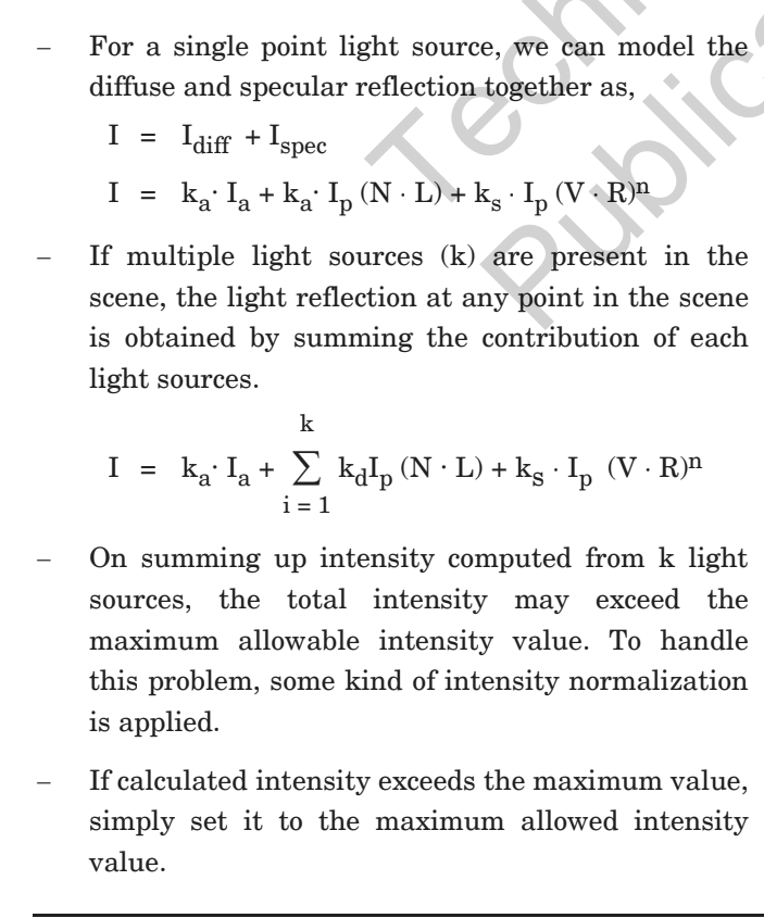
151 | > * 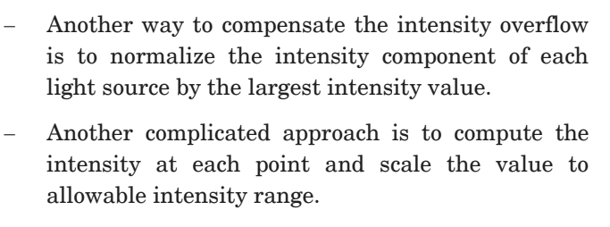
152 |
153 | ---
154 |
155 | * Warn Model:
156 | > * Warn model provides a way to model the studio light with varying intensity in different directions.
157 | > * 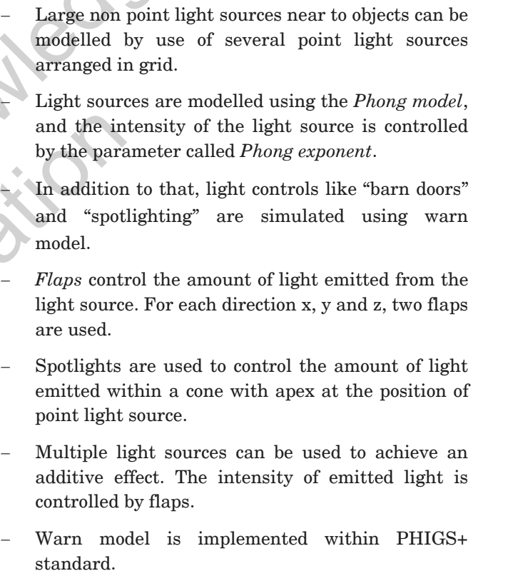
158 |
159 | ---
160 |
161 | ## Shading Algorithms:
162 | * Gauraud Shading:
163 | > * Flat shading/Constant intensity shading:
164 | > * We get discontinuity in flat shading so we use gauraud shading.
165 | > * Steps:
166 | > * Determine the average unit normal vector at each polygon vertex.
167 | > * Apply illumination model to each polygon vertex to determine polygon vertex intensity.
168 | > * Linearly interpolate the vertex intensities over the surface of polygon.
169 | > * 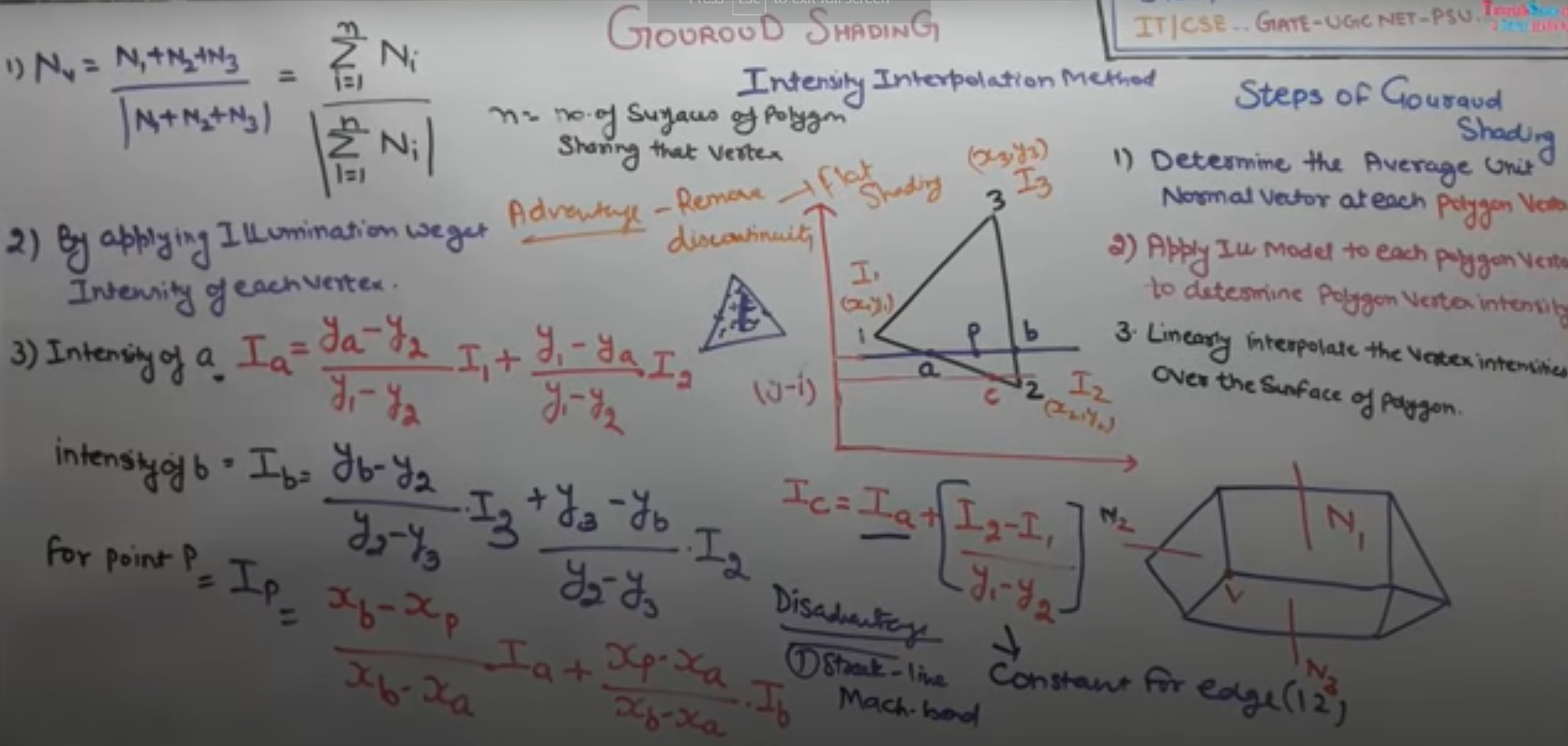
170 | >
171 | ---
172 |
173 | * Phong Shading/Normal Vector interpolation shading:
174 | > * Steps:
175 | > * Determine the average unit normal vector at each polygon vertex.
176 | > * Linearly interpolate the vertex normals over the surface of polygon.
177 | > * Apply the illumination model along each scan to determine projected pixel intensities of surface points.
178 | > * 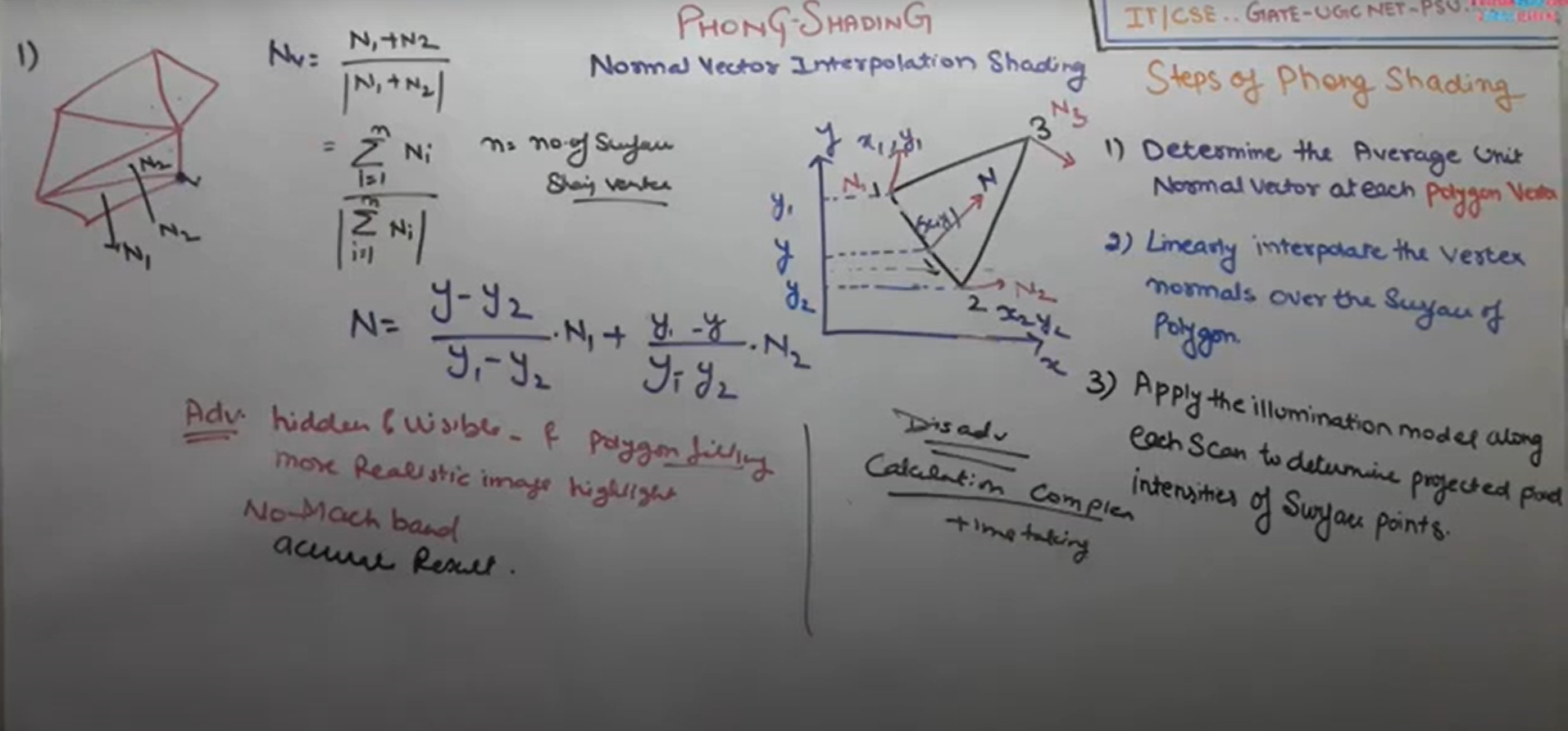
179 |
180 | ---
181 |
182 | * Halftone Shading:
183 | > * Halftoning is used on a device supporting a limited intensity range.
184 | > * Halftoning improves the quality of the picture by increasing visual resolution using a minimum number of intensity levels. This method is also known as patterning.
185 | > * Halftoning is used to reproduce the photographs for newspapers and magazines. This process is called halftoning and the reproduced image is called halftoning.
186 | > * Halftone image looks like as if it is composed of black circles of different radius. The dark region is produced using large circles. Light regions are produced by small circles. Good qualitiy books and mazine are printed using approximately 60-80 circles of varying radius per centimetre.
187 | > * Example:
188 | > * 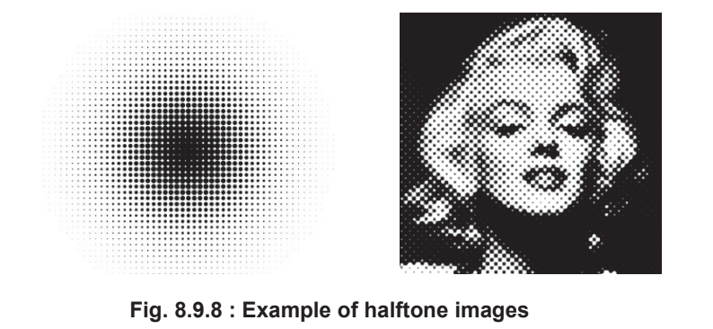
189 |
190 | ---
191 |
192 | * Difference between gourauld and phong shading:
193 | > * 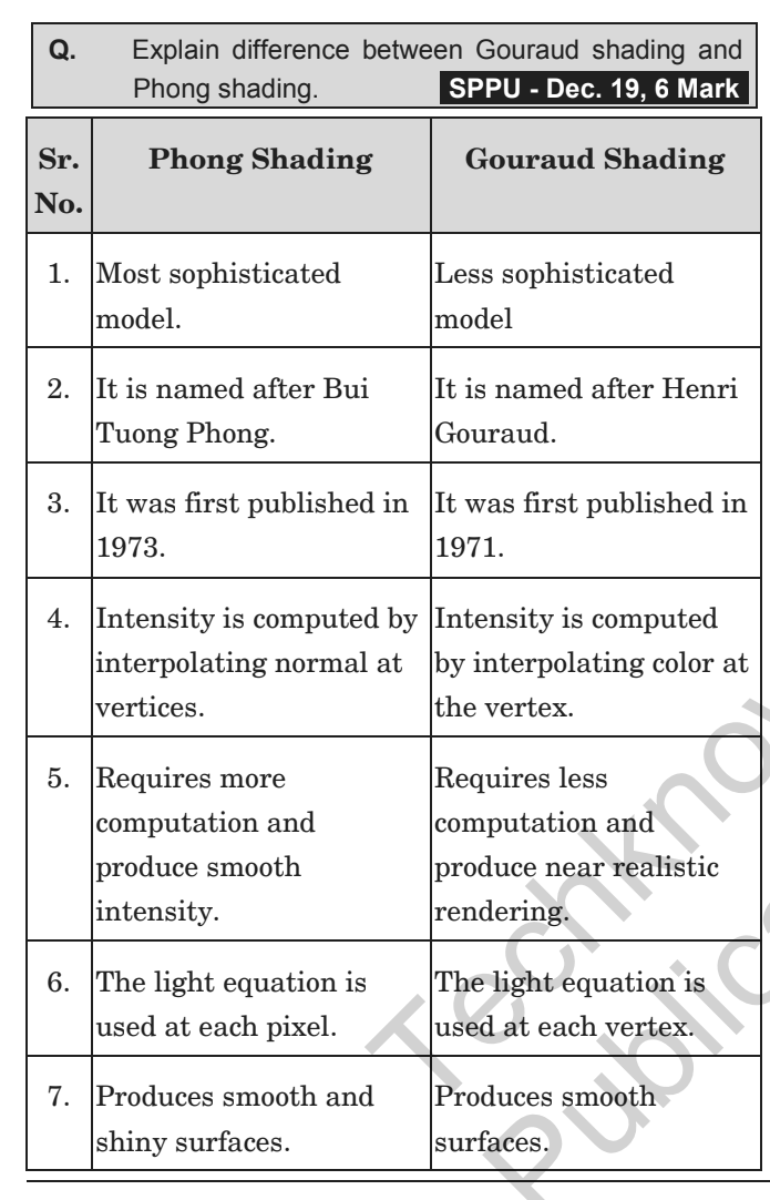
194 |
195 |
196 | ----
197 |
198 | ## Hidden Surfaces:
199 |
200 | * Hidden Surfaces:
201 | > * Visible surface detection algorithms are also known as hidden line or hidden surface removal algorithms.
202 | > * Aim of such algorithms is to identify the visible lines or surfaces of a given set of object from particular viewing direction.
203 |
204 | ---
205 |
206 | * Back Face Detection and Removal:
207 | > * Sometimes visible surface detection is also referred to as hidden surface removal of back face detection.
208 | > * 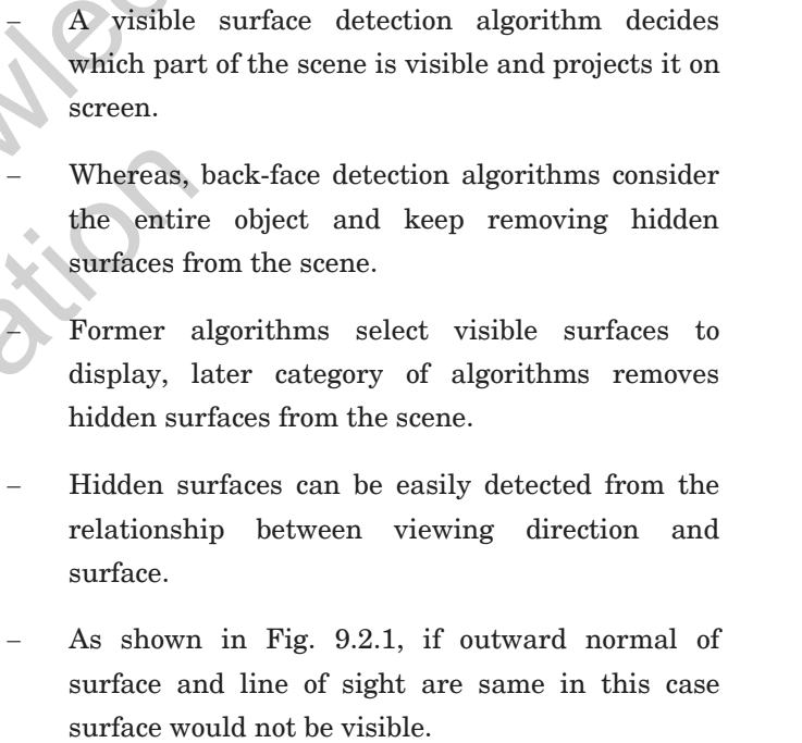
209 | > * 
210 | > * 
211 | > * 
212 |
213 | ---
214 |
215 | * Depth Buffer:
216 | > * Depth Buffer method is also known as the z buffer method.
217 | > * This is an image space approach.
218 | > * It compares the depth of the pixels of overlapping objects into the scene and renders the nearest pixel to the viewer.
219 | > * This algorithm is generally applied on normalized co-ordinates, where all values fall between 0 and 1.
220 | > * This algorithm is an extension of the idea of the frame buffer. Implementation requieres two buffers.
221 | >
222 |
223 | ----
224 |
225 | > * P.S. Refer to Book for Depth Buffer algo + depth sort + Warnock
226 | > * Done Unit IV - Light, Colour, Shading and Hidden surfaces.
227 |
--------------------------------------------------------------------------------