├── Production
└── Serial-7-Segment-Display_Panel_v31b.brd
├── README.md
├── firmware
├── README.md
└── Serial 7-Segment Display
│ ├── Arduino_Examples
│ ├── S7S_Example_I2C_Basic
│ │ └── S7S_Example_I2C_Basic.ino
│ ├── S7S_Example_I2C_ChangeAddress
│ │ └── S7S_Example_I2C_ChangeAddress.ino
│ ├── S7S_Example_I2C_Settings
│ │ └── S7S_Example_I2C_Settings.ino
│ ├── S7S_Example_SPI_Basic
│ │ └── S7S_Example_SPI_Basic.ino
│ ├── S7S_Example_SPI_Settings
│ │ └── S7S_Example_SPI_Settings.ino
│ ├── S7S_Example_Serial_Basic
│ │ └── S7S_Example_Serial_Basic.ino
│ ├── S7S_Example_Serial_Brightness
│ │ └── S7S_Example_Serial_Brightness.ino
│ ├── S7S_Example_Serial_ColonDots
│ │ └── S7S_Example_Serial_ColonDots.ino
│ ├── S7S_Example_Serial_Mode_Change
│ │ └── S7S_Example_Serial_Mode_Change.ino
│ ├── S7S_Example_Serial_Predator
│ │ └── S7S_Example_Serial_Predator.ino
│ ├── S7S_Example_Serial_Settings
│ │ └── S7S_Example_Serial_Settings.ino
│ └── S7S_Example_Serial_SoftwareReset
│ │ └── S7S_Example_Serial_SoftwareReset.ino
│ └── Serial_7_Segment_Display_Firmware
│ ├── Serial_7_Segment_Display_Firmware.ino
│ ├── System_Functions.ino
│ └── settings.h
└── hardware
├── README.txt
├── Serial-7-Segment-Display.brd
├── Serial-7-Segment-Display.pdf
└── Serial-7-Segment-Display.sch
/README.md:
--------------------------------------------------------------------------------
1 | 7-Segment Serial Display
2 | ========================
3 |
4 | [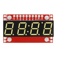
5 | *7-Segment Serial Display (COM-11629)*](https://www.sparkfun.com/products/11629)
6 |
7 | The 7-Segment Serial Display combines a classic 4-digit 7-segment display and an ATMega328 microcontroller allowing you to control every segment individually using only a few serial lines.
8 |
9 | Repository Contents
10 | -------------------
11 |
12 | * **/firmware** - Arduino firmware and test code
13 | * **/hardware** - PCB design files (created with Eagle 6.1.0)
14 |
15 | Documentation
16 | --------------
17 | * **[Hookup Guide](https://learn.sparkfun.com/tutorials/using-the-serial-7-segment-display)** - Basic hookup guide for the Serial Enabled 7-Segment Displays.
18 | * **[Datasheet](https://github.com/sparkfun/Serial7SegmentDisplay/wiki/Serial-7-Segment-Display-Datasheet)** - Specifications
19 |
20 | Product Versions
21 | ----------------
22 |
23 | **[COM-11629](https://www.sparkfun.com/products/11629) - white, OEM packaging**
24 | The 7-Segment Serial Display with **white** segments in standard OEM packaging.
25 |
26 | **[COM-11442](https://www.sparkfun.com/products/11442) - blue, OEM packaging**
27 | The 7-Segment Serial Display with **blue** segments in standard OEM packaging.
28 |
29 | **[COM-11441](https://www.sparkfun.com/products/11441) - red, OEM packaging**
30 | The 7-Segment Serial Display with **red** segments in standard OEM packaging.
31 |
32 | **[COM-11443](https://www.sparkfun.com/products/11443) - yellow, OEM packaging**
33 | The 7-Segment Serial Display with **yellow** segments in standard OEM packaging.
34 |
35 | **[COM-11440](https://www.sparkfun.com/products/11440) - kelly green, OEM packaging**
36 | The 7-Segment Serial Display with **kelly green** segments in standard OEM packaging.
37 |
38 | **[RTL-11381](https://www.sparkfun.com/products/11381) - blue, retail packaging**
39 | The 7-Segment Serial Display with **blue** segments in a retail-ready plastic clam shell.
40 |
41 | **[RTL-11386](https://www.sparkfun.com/products/11386) - red, retail packaging**
42 | The 7-Segment Serial Display with **red** segments in a retail-ready plastic clam shell.
43 |
44 | License Information
45 | -------------------
46 |
47 | All contents of this repository are released under [Creative Commons Share-alike 3.0](http://creativecommons.org/licenses/by-sa/3.0/).
48 |
49 | Author
50 | ------
51 |
52 | Jim Lindblom, [SparkFun Electronics](https://www.sparkfun.com)
53 |
--------------------------------------------------------------------------------
/firmware/README.md:
--------------------------------------------------------------------------------
1 | //////////////////////////////////////
2 | /// Serial 7-Segment Display /////////
3 | //////////////////////////////////////
4 |
5 | This folder should live in your Arduino Sketchbook.
6 |
7 | Serial 7-Segment Display: This folder contains the Serial 7-Segment Displays firmware and test/example Arduino code.
8 |
9 | Support for this board in the Arduino IDE can be found in [this repository](https://github.com/sparkfun/Arduino_Boards/). That adds a "Serial 7-Segment Display" option to the boards menu within Arduino. If you reprogram the Display, you'll need this board selected. Special pin defines were required to make use of new pins 22 and 23 (PB6:7) (in variants/standard/pins_arduino.h). These pins are available on the Serial 7-Segment Display because it runs on the ATmega328's internal 8MHz oscillator.
10 |
11 | This project is Open-source!
12 |
13 | License: Creative Commons Attribution-ShareAlike 4.0 (CC BY-SA 4.0)
14 | https://creativecommons.org/licenses/by-sa/4.0/
15 |
--------------------------------------------------------------------------------
/firmware/Serial 7-Segment Display/Arduino_Examples/S7S_Example_I2C_Basic/S7S_Example_I2C_Basic.ino:
--------------------------------------------------------------------------------
1 | /*
2 | 11-2-2012
3 | Spark Fun Electronics
4 | Nathan Seidle
5 |
6 | This code is public domain but you buy me a beer if you use this and we meet someday (Beerware license).
7 |
8 | Serial7Segment is an open source seven segment display.
9 |
10 | This is example code that shows how to send data over I2C to the display.
11 |
12 | Please Note: 0x71 is the 7-bit I2C address. If you are using a different language than Arduino you will probably
13 | need to add the Read/Write bit to the end of the address. This means the default read address for the OpenSegment
14 | is 0b.1110.0011 or 0xE3 and the write address is 0b.1110.0010 or 0xE2.
15 | For more information see https://learn.sparkfun.com/tutorials/i2c
16 |
17 | Note: This code expects the display to be listening at the default I2C address. If your display is not at 0x71, you can
18 | do a software or hardware reset. See the Wiki for more info:
19 | http://github.com/sparkfun/Serial7SegmentDisplay/wiki/Special-Commands
20 |
21 | To get this code to work, attached an Serial7Segment to an Arduino Uno using the following pins:
22 | A5 to SCL
23 | A4 to SDA
24 | VIN to PWR
25 | GND to GND
26 |
27 | For this example pull up resistors are not needed on SDA and SCL. If you have other devices on the
28 | I2C bus then 4.7k pull up resistors are recommended.
29 |
30 | OpenSegment will work at 400kHz Fast I2C. Use the .setClock() call shown below to set the data rate
31 | faster if needed.
32 |
33 | */
34 |
35 | #include
36 |
37 | #define DISPLAY_ADDRESS1 0x71 //This is the default address of the OpenSegment with both solder jumpers open
38 |
39 | int cycles = 0;
40 |
41 | void setup()
42 | {
43 | Wire.begin(); //Join the bus as master
44 |
45 | //By default .begin() will set I2C SCL to Standard Speed mode of 100kHz
46 | //Wire.setClock(400000); //Optional - set I2C SCL to High Speed Mode of 400kHz
47 |
48 | Serial.begin(9600); //Start serial communication at 9600 for debug statements
49 | Serial.println("OpenSegment Example Code");
50 |
51 | //Send the reset command to the display - this forces the cursor to return to the beginning of the display
52 | Wire.beginTransmission(DISPLAY_ADDRESS1);
53 | Wire.write('v');
54 | Wire.endTransmission();
55 | }
56 |
57 | void loop()
58 | {
59 | cycles++; //Counting cycles! Yay!
60 | Serial.print("Cycle: ");
61 | Serial.println(cycles);
62 |
63 | i2cSendValue(cycles); //Send the four characters to the display
64 |
65 | delay(1); //If we remove the slow debug statements, we need a very small delay to prevent flickering
66 | }
67 |
68 | //Given a number, i2cSendValue chops up an integer into four values and sends them out over I2C
69 | void i2cSendValue(int tempCycles)
70 | {
71 | Wire.beginTransmission(DISPLAY_ADDRESS1); // transmit to device #1
72 | Wire.write(tempCycles / 1000); //Send the left most digit
73 | tempCycles %= 1000; //Now remove the left most digit from the number we want to display
74 | Wire.write(tempCycles / 100);
75 | tempCycles %= 100;
76 | Wire.write(tempCycles / 10);
77 | tempCycles %= 10;
78 | Wire.write(tempCycles); //Send the right most digit
79 | Wire.endTransmission(); //Stop I2C transmission
80 | }
81 |
--------------------------------------------------------------------------------
/firmware/Serial 7-Segment Display/Arduino_Examples/S7S_Example_I2C_ChangeAddress/S7S_Example_I2C_ChangeAddress.ino:
--------------------------------------------------------------------------------
1 | /*
2 | OpenSegment is an 7-segment display with Serial/I2C/SPI interfaces.
3 | By: Nathan Seidle
4 | SparkFun Electronics
5 | Date: June 11th, 2015
6 | License: This code is public domain but you buy me a beer if you use this and we meet someday (Beerware license).
7 |
8 | OpenSegment gives the user multiple interfaces (serial, I2C, and SPI) to control a four digit
9 | seven segment display.
10 |
11 | This example shows how to change the I2C or TWI address.
12 |
13 | Please Note: 0x71 is the 7-bit I2C address. If you are using a different language than Arduino you will probably
14 | need to add the Read/Write bit to the end of the address. This means the default read address for the OpenSegment
15 | is 0b.1110.0011 or 0xE3 and the write address is 0b.1110.0010 or 0xE2.
16 | For more information see https://learn.sparkfun.com/tutorials/i2c
17 |
18 | Note: This code expects the display to be listening at the default I2C address. If your display is not at 0x71, you can
19 | do a software or hardware reset. See the Wiki for more info:
20 | http://github.com/sparkfun/Serial7SegmentDisplay/wiki/Special-Commands
21 |
22 | To get this code to work, attached a Serial7Segment to an Arduino Uno using the following pins:
23 | SCL (OpenSegment) to A5 (Arduino)
24 | SDA to A4
25 | VIN to 5V
26 | GND to GND
27 |
28 | For this example pull up resistors are not needed on SDA and SCL. If you have other devices on the
29 | I2C bus then 4.7k pull up resistors are recommended.
30 |
31 | OpenSegment will work at 400kHz Fast I2C. Use the .setClock() call shown below to set the data rate
32 | faster if needed.
33 |
34 | */
35 |
36 | #include
37 |
38 | #define DISPLAY_ADDRESS1 0x71 //This is the default address of the OpenSegment
39 | #define DISPLAY_ADDRESS_NEW 0x50 //This is the new I2C address we want to go to
40 |
41 | int cycles = 0;
42 |
43 | void setup()
44 | {
45 | Wire.begin(); //Join the bus as master
46 |
47 | //By default .begin() will set I2C SCL to Standard Speed mode of 100kHz
48 | //Wire.setClock(400000); //Optional - set I2C SCL to High Speed Mode of 400kHz
49 |
50 | Serial.begin(9600); //Start serial communication at 9600 for debug statements
51 | Serial.println("OpenSegment Example Code");
52 |
53 | //Send the reset command to the display - this forces the cursor to return to the beginning of the display
54 | Wire.beginTransmission(DISPLAY_ADDRESS1);
55 | Wire.write('v');
56 | Wire.endTransmission();
57 |
58 | //Send change address command
59 | Wire.beginTransmission(DISPLAY_ADDRESS1); // transmit to device #1
60 | Wire.write(0x80); //Send TWI address change command
61 | Wire.write(DISPLAY_ADDRESS_NEW); //New I2C address to use
62 | Wire.endTransmission(); //Stop I2C transmission
63 |
64 | Serial.println("I2C address changed to 0x50");
65 |
66 | //Now we talk at this new address
67 |
68 | //Send the reset command to the display - this forces the cursor to return to the beginning of the display
69 | Wire.beginTransmission(DISPLAY_ADDRESS_NEW);
70 | Wire.write('v');
71 | Wire.endTransmission();
72 | }
73 |
74 | void loop()
75 | {
76 | cycles++; //Counting cycles! Yay!
77 | Serial.print("Cycle: ");
78 | Serial.println(cycles);
79 |
80 | i2cSendValue(cycles); //Send the four characters to the display
81 |
82 | delay(1); //If we remove the slow debug statements, we need a very small delay to prevent flickering
83 | }
84 |
85 | //Given a number, i2cSendValue chops up an integer into four values and sends them out over I2C
86 | void i2cSendValue(int tempCycles)
87 | {
88 | Wire.beginTransmission(DISPLAY_ADDRESS_NEW); // transmit to device at new I2C address
89 | Wire.write(tempCycles / 1000); //Send the left most digit
90 | tempCycles %= 1000; //Now remove the left most digit from the number we want to display
91 | Wire.write(tempCycles / 100);
92 | tempCycles %= 100;
93 | Wire.write(tempCycles / 10);
94 | tempCycles %= 10;
95 | Wire.write(tempCycles); //Send the right most digit
96 | Wire.endTransmission(); //Stop I2C transmission
97 | }
98 |
--------------------------------------------------------------------------------
/firmware/Serial 7-Segment Display/Arduino_Examples/S7S_Example_I2C_Settings/S7S_Example_I2C_Settings.ino:
--------------------------------------------------------------------------------
1 | /*
2 | 11-2-2012
3 | Spark Fun Electronics
4 | Nathan Seidle
5 |
6 | This code is public domain but you buy me a beer if you use this and we meet someday (Beerware license).
7 |
8 | Serial7Segment is an open source seven segment display.
9 |
10 | This is example code that shows how to control the brightness level of the display over I2C.
11 |
12 | Please Note: 0x71 is the 7-bit I2C address. If you are using a different language than Arduino you will probably
13 | need to add the Read/Write bit to the end of the address. This means the default read address for the OpenSegment
14 | is 0b.1110.0011 or 0xE3 and the write address is 0b.1110.0010 or 0xE2.
15 | For more information see https://learn.sparkfun.com/tutorials/i2c
16 |
17 | Note: This code expects the display to be listening at the default I2C address. If your display is not at 0x71, you can
18 | do a software or hardware reset. See the Wiki for more info:
19 | http://github.com/sparkfun/Serial7SegmentDisplay/wiki/Special-Commands
20 |
21 | To get this code to work, attached an Serial7Segment to an Arduino Uno using the following pins:
22 | A5 to SCL
23 | A4 to SDA
24 | VIN to PWR
25 | GND to GND
26 |
27 | For this example pull up resistors are not needed on SDA and SCL. If you have other devices on the
28 | I2C bus then 4.7k pull up resistors are recommended.
29 |
30 | OpenSegment will work at 400kHz Fast I2C. Use the .setClock() call shown below to set the data rate
31 | faster if needed.
32 |
33 | */
34 |
35 | #include
36 |
37 | #define DISPLAY_ADDRESS1 0x71 //This is the default address of the OpenSegment with both solder jumpers open
38 |
39 | void setup()
40 | {
41 | Wire.begin(); //Join the bus as master
42 |
43 | //By default .begin() will set I2C SCL to Standard Speed mode of 100kHz
44 | //Wire.setClock(400000); //Optional - set I2C SCL to High Speed Mode of 400kHz
45 |
46 | Serial.begin(9600); //Start serial communication at 9600 for debug statements
47 | Serial.println("OpenSegment Example Code");
48 |
49 | //Send the reset command to the display - this forces the cursor to return to the beginning of the display
50 | Wire.beginTransmission(DISPLAY_ADDRESS1);
51 | Wire.write('v');
52 | Wire.endTransmission();
53 | }
54 |
55 | void loop()
56 | {
57 | Serial.println("Low brightness"); //Just a debug statement
58 | Wire.beginTransmission(DISPLAY_ADDRESS1);
59 | Wire.write(0x7A); // Brightness control command
60 | Wire.write(0); // Set brightness level: 0% to 100%
61 | Wire.endTransmission();
62 | i2cSendString("b000"); //Send the four characters to the display
63 | delay(2000); //Hang out for a bit before we go to the next brightness level
64 |
65 | Serial.println("Mid brightness"); //Just a debug statement
66 | Wire.beginTransmission(DISPLAY_ADDRESS1);
67 | Wire.write(0x7A); // Brightness control command
68 | Wire.write(50); // Set brightness level: 0% to 100%
69 | Wire.endTransmission();
70 | i2cSendString("b050"); //Send the four characters to the display
71 | delay(2000); //Hang out for a bit before we go to the next brightness level
72 |
73 | Serial.println("High brightness"); //Just a debug statement
74 | Wire.beginTransmission(DISPLAY_ADDRESS1);
75 | Wire.write(0x7A); // Brightness control command
76 | Wire.write(100); // Set brightness level: 0% to 100%
77 | Wire.endTransmission();
78 | i2cSendString("b100"); //Send the four characters to the display
79 | delay(2000); //Hang out for a bit before we go to the next brightness level
80 | }
81 |
82 | //Given a string, i2cSendString chops up the string and sends out the first four characters over i2c
83 | void i2cSendString(char *toSend)
84 | {
85 | Wire.beginTransmission(DISPLAY_ADDRESS1); // transmit to device #1
86 | for(byte x = 0 ; x < 4 ; x++)
87 | Wire.write(toSend[x]); //Send a character from the array out over I2C
88 | Wire.endTransmission(); //Stop I2C transmission
89 | }
90 |
--------------------------------------------------------------------------------
/firmware/Serial 7-Segment Display/Arduino_Examples/S7S_Example_SPI_Basic/S7S_Example_SPI_Basic.ino:
--------------------------------------------------------------------------------
1 | /*
2 | 11-2-2012
3 | Spark Fun Electronics
4 | Nathan Seidle
5 |
6 | This code is public domain but you buy me a beer if you use this and we meet someday (Beerware license).
7 |
8 | Serial7Segment is an open source seven segment display.
9 |
10 | This is example code that shows how to send data over SPI to the display.
11 |
12 | For more information about the commands, be sure to visit:
13 | http://github.com/sparkfun/Serial7SegmentDisplay/wiki/Special-Commands
14 |
15 | To get this code to work, attached an OpenSegment to an Arduino Uno using the following pins:
16 | Pin 10 on Uno (CS) to CS on OpenSegment
17 | Pin 11 to MOSI
18 | Pin 12 to MISO
19 | Pin 13 to SCK
20 | VIN to PWR
21 | GND to GND
22 |
23 | */
24 |
25 | #include
26 |
27 | int csPin = 10; //You can use any IO pin but for this example we use 10
28 |
29 | int cycles = 0;
30 |
31 | void setup()
32 | {
33 | pinMode(csPin, OUTPUT);
34 | digitalWrite(csPin, HIGH); //By default, don't be selecting OpenSegment
35 |
36 | Serial.begin(9600); //Start serial communication at 9600 for debug statements
37 | Serial.println("OpenSegment Example Code");
38 |
39 | SPI.begin(); //Start the SPI hardware
40 | SPI.setClockDivider(SPI_CLOCK_DIV64); //Slow down the master a bit
41 |
42 | //Send the reset command to the display - this forces the cursor to return to the beginning of the display
43 | digitalWrite(csPin, LOW); //Drive the CS pin low to select OpenSegment
44 | SPI.transfer('v'); //Reset command
45 | }
46 |
47 | void loop()
48 | {
49 | cycles++; //Counting cycles! Yay!
50 | Serial.print("Cycle: ");
51 | Serial.println(cycles);
52 |
53 | spiSendValue(cycles); //Send the four characters to the display
54 |
55 | delay(1); //If we remove the slow debug statements, we need a very small delay to prevent flickering
56 | }
57 |
58 | //Given a number, spiSendValue chops up an integer into four values and sends them out over spi
59 | void spiSendValue(int tempCycles)
60 | {
61 | digitalWrite(csPin, LOW); //Drive the CS pin low to select OpenSegment
62 |
63 | SPI.transfer(tempCycles / 1000); //Send the left most digit
64 | tempCycles %= 1000; //Now remove the left most digit from the number we want to display
65 | SPI.transfer(tempCycles / 100);
66 | tempCycles %= 100;
67 | SPI.transfer(tempCycles / 10);
68 | tempCycles %= 10;
69 | SPI.transfer(tempCycles); //Send the right most digit
70 |
71 | digitalWrite(csPin, HIGH); //Release the CS pin to de-select OpenSegment
72 | }
73 |
--------------------------------------------------------------------------------
/firmware/Serial 7-Segment Display/Arduino_Examples/S7S_Example_SPI_Settings/S7S_Example_SPI_Settings.ino:
--------------------------------------------------------------------------------
1 | /*
2 | 11-2-2012
3 | Spark Fun Electronics
4 | Nathan Seidle
5 |
6 | This code is public domain but you buy me a beer if you use this and we meet someday (Beerware license).
7 |
8 | Serial7Segment is an open source seven segment display.
9 |
10 | This is example code that shows how to send data over SPI to the display.
11 |
12 | For more information about the commands, be sure to visit:
13 | http://github.com/sparkfun/Serial7SegmentDisplay/wiki/Special-Commands
14 |
15 | To get this code to work, attached an OpenSegment to an Arduino Uno using the following pins:
16 | Pin 10 on Uno (CS) to CS on OpenSegment
17 | Pin 11 to MOSI
18 | Pin 12 to MISO
19 | Pin 13 to SCK
20 | VIN to PWR
21 | GND to GND
22 |
23 | */
24 |
25 | #include
26 |
27 | int csPin = 10; //You can use any IO pin but for this example we use 10
28 |
29 | int cycles = 0;
30 |
31 | void setup()
32 | {
33 | pinMode(csPin, OUTPUT);
34 | digitalWrite(csPin, HIGH); //By default, don't be selecting OpenSegment
35 |
36 | Serial.begin(9600); //Start serial communication at 9600 for debug statements
37 | Serial.println("OpenSegment Example Code");
38 |
39 | SPI.begin(); //Start the SPI hardware
40 | SPI.setClockDivider(SPI_CLOCK_DIV16); //Slow down the master a bit
41 |
42 | //Send the reset command to the display - this forces the cursor to return to the beginning of the display
43 | digitalWrite(csPin, LOW); //Drive the CS pin low to select OpenSegment
44 | SPI.transfer('v'); //Reset command
45 | digitalWrite(csPin, HIGH); //Release the CS pin to de-select OpenSegment
46 | }
47 |
48 | void loop()
49 | {
50 | Serial.println("Low brightness"); //Just a debug statement
51 | digitalWrite(csPin, LOW); //Drive the CS pin low to select OpenSegment
52 | SPI.transfer(0x7A); // Brightness control command
53 | delay(1); //Small delay between bytes so S7S can buffer them
54 | SPI.transfer(0); // Set brightness level: 0% to 100%
55 | digitalWrite(csPin, HIGH); //Release the CS pin to de-select OpenSegment
56 | delay(1); //Small delay between bytes so S7S can buffer them
57 |
58 | spiSendString("b000"); //Send the four characters to the display
59 | delay(2000); //Hang out for a bit before we go to the next brightness level
60 |
61 | Serial.println("Mid brightness"); //Just a debug statement
62 | digitalWrite(csPin, LOW); //Drive the CS pin low to select OpenSegment
63 | SPI.transfer(0x7A); // Brightness control command
64 | delay(1); //Small delay between bytes so S7S can buffer them
65 | SPI.transfer(50); // Set brightness level: 0% to 100%
66 | digitalWrite(csPin, HIGH); //Release the CS pin to de-select OpenSegment
67 | delay(1); //Small delay between bytes so S7S can buffer them
68 |
69 | spiSendString("b050"); //Send the four characters to the display
70 | delay(2000); //Hang out for a bit before we go to the next brightness level
71 |
72 | Serial.println("High brightness"); //Just a debug statement
73 | digitalWrite(csPin, LOW); //Drive the CS pin low to select OpenSegment
74 | SPI.transfer(0x7A); // Brightness control command
75 | delay(1); //Small delay between bytes so S7S can buffer them
76 | SPI.transfer(100); // Set brightness level: 0% to 100%
77 | digitalWrite(csPin, HIGH); //Release the CS pin to de-select OpenSegment
78 | delay(1); //Small delay between bytes so S7S can buffer them
79 |
80 | spiSendString("b100"); //Send the four characters to the display
81 | delay(2000); //Hang out for a bit before we go to the next brightness level
82 | }
83 |
84 | //Given a string, spiSendString chops up the string and sends out the first four characters over spi
85 | void spiSendString(char *toSend)
86 | {
87 | digitalWrite(csPin, LOW); //Drive the CS pin low to select OpenSegment
88 | SPI.transfer('v'); //Reset command
89 | digitalWrite(csPin, HIGH); //Release the CS pin to de-select OpenSegment
90 |
91 | digitalWrite(csPin, LOW); //Drive the CS pin low to select OpenSegment
92 | for(byte x = 0 ; x < 4 ; x++)
93 | {
94 | delay(1); //Small delay between bytes so S7S can buffer them
95 | SPI.transfer(toSend[x]); //Send a character from the array out over I2C
96 | }
97 | digitalWrite(csPin, HIGH); //Release the CS pin to de-select OpenSegment
98 | }
99 |
--------------------------------------------------------------------------------
/firmware/Serial 7-Segment Display/Arduino_Examples/S7S_Example_Serial_Basic/S7S_Example_Serial_Basic.ino:
--------------------------------------------------------------------------------
1 | /*
2 | 9-23-2012
3 | Spark Fun Electronics
4 | Nathan Seidle
5 |
6 | This code is public domain but you buy me a beer if you use this and we meet someday (Beerware license).
7 |
8 | Serial7Segment is an open source seven segment display.
9 |
10 | This is example code that shows how to display basic numbers on the display.
11 |
12 | Note: This code expects the display to be listening at 9600bps. If your display is not at 9600bps, you can
13 | do a software or hardware reset. See the Wiki for more info:
14 | http://github.com/sparkfun/Serial7SegmentDisplay/wiki/Special-Commands#wiki-baud
15 |
16 | To get this code to work, attached an Serial7Segment to an Arduino Uno using the following pins:
17 | Pin 8 on Uno (software serial TX) to RX on Serial7Segment
18 | VIN to PWR
19 | GND to GND
20 |
21 | */
22 |
23 | #include
24 |
25 | SoftwareSerial Serial7Segment(7, 8); //RX pin, TX pin
26 |
27 | int cycles = 0;
28 |
29 | void setup() {
30 |
31 | Serial.begin(9600);
32 | Serial.println("OpenSegment Example Code");
33 |
34 | Serial7Segment.begin(9600); //Talk to the Serial7Segment at 9600 bps
35 | Serial7Segment.write('v'); //Reset the display - this forces the cursor to return to the beginning of the display
36 | }
37 |
38 | void loop()
39 | {
40 | cycles++; //Counting cycles! Yay!
41 | Serial.print("Cycle: ");
42 | Serial.println(cycles);
43 |
44 | char tempString[10]; //Used for sprintf
45 | sprintf(tempString, "%4d", cycles); //Convert deciSecond into a string that is right adjusted
46 | //sprintf(tempString, "%d", cycles); //Convert deciSecond into a string that is left adjusted (requires digit 1 command)
47 | //sprintf(tempString, "%04d", cycles); //Convert deciSecond into a string with leading zeros
48 | //sprintf(tempString, "%4X", cycles); //Count in HEX, right adjusted
49 | //int negativeCycles = cycles * -1;
50 | //sprintf(tempString, "%4d", negativeCycles); //Shows a negative sign infront of right adjusted number
51 |
52 | //Note: This method works well as long as your number is less than or equal to 4 digits.
53 | //14422 will cause the display to wrap (5 digits)
54 | //-5766 will cause the display to wrap (5 digits)
55 | //To fix this, send a 'v' character or look at how to control the digit placement
56 | //https://github.com/sparkfun/Serial7SegmentDisplay/wiki/Basic-Usage#wiki-cursor
57 |
58 | Serial7Segment.print(tempString); //Send serial string out the soft serial port to the S7S
59 |
60 | delay(10);
61 | }
62 |
63 |
64 |
65 |
--------------------------------------------------------------------------------
/firmware/Serial 7-Segment Display/Arduino_Examples/S7S_Example_Serial_Brightness/S7S_Example_Serial_Brightness.ino:
--------------------------------------------------------------------------------
1 | /*
2 | 9-23-2012
3 | Spark Fun Electronics
4 | Nathan Seidle
5 |
6 | This code is public domain but you buy me a beer if you use this and we meet someday (Beerware license).
7 |
8 | Serial7Segment is an open source seven segment display.
9 |
10 | This example code shows how to control the brightness and other system settings on S7S.
11 |
12 | To get this code to work, attached an Serial7Segment to an Arduino Uno using the following pins:
13 | Pin 7 on Uno (software serial RX) to TX on Serial7Segment
14 | Pin 8 on Uno to RX on Serial7Segment
15 | VIN to PWR
16 | GND to GND
17 |
18 | */
19 |
20 | #include
21 |
22 | SoftwareSerial Serial7Segment(7, 8); //RX pin, TX pin
23 |
24 | char tempString[10]; //Used for sprintf
25 | byte brightnessLevel = 0;
26 |
27 | void setup()
28 | {
29 | Serial.begin(9600);
30 | Serial.println("OpenSegment Example Code");
31 |
32 | Serial7Segment.begin(9600); //Talk to the Serial7Segment at 9600 bps
33 | Serial7Segment.write('v'); //Reset the display - this forces the cursor to return to the beginning of the display
34 | }
35 |
36 | void loop()
37 | {
38 | //Set the display to three different levels to show brightness example
39 |
40 | brightnessLevel = 0; //0% brightness
41 | Serial.print("brightnessLevel: ");
42 | Serial.println(brightnessLevel);
43 | Serial7Segment.write(0x7A); // Brightness control command
44 | Serial7Segment.write((byte) brightnessLevel); // 0 is dimmest, 255 is brightest
45 | sprintf(tempString, "b%03d", brightnessLevel); //Convert deciSecond into a string that is right adjusted
46 | Serial7Segment.print(tempString);
47 | delay(2000);
48 |
49 | brightnessLevel = 50; //50% brightness
50 | Serial.print("brightnessLevel: ");
51 | Serial.println(brightnessLevel);
52 | Serial7Segment.write(0x7A); // Brightness control command
53 | Serial7Segment.write((byte) brightnessLevel); // 0 is dimmest, 255 is brightest
54 | sprintf(tempString, "b%03d", brightnessLevel); //Convert deciSecond into a string that is right adjusted
55 | Serial7Segment.print(tempString);
56 | delay(2000);
57 |
58 | brightnessLevel = 100; //100% brightness
59 | Serial.print("brightnessLevel: ");
60 | Serial.println(brightnessLevel);
61 | Serial7Segment.write(0x7A); // Brightness control command
62 | Serial7Segment.write((byte) brightnessLevel); // 0 is dimmest, 255 is brightest
63 | sprintf(tempString, "b%03d", brightnessLevel); //Convert deciSecond into a string that is right adjusted
64 | Serial7Segment.print(tempString);
65 | delay(2000);
66 | }
67 |
--------------------------------------------------------------------------------
/firmware/Serial 7-Segment Display/Arduino_Examples/S7S_Example_Serial_ColonDots/S7S_Example_Serial_ColonDots.ino:
--------------------------------------------------------------------------------
1 | /*
2 | 11-4-2012
3 | Spark Fun Electronics
4 | Nathan Seidle
5 |
6 | This code is public domain but you buy me a beer if you use this and we meet someday (Beerware license).
7 |
8 | Serial7Segment is an open source seven segment display.
9 |
10 | This is example code that shows how to display basic numbers and control the decimal, colon, and AM/PM dot.
11 |
12 | Note: This code works with displays the support the center colon and extra dots (AM/PM, not decimals).
13 |
14 | Note: This code expects the display to be listening at 9600bps. If your display is not at 9600bps, you can
15 | do a software or hardware reset. See the Wiki for more info:
16 | http://github.com/sparkfun/Serial7SegmentDisplay/wiki/Special-Commands#wiki-baud
17 |
18 | To get this code to work, attached an Serial7Segment to an Arduino Uno using the following pins:
19 | Pin 7 on Uno (software serial RX) to TX on Serial7Segment
20 | Pin 8 on Uno to RX on Serial7Segment
21 | VIN to PWR
22 | GND to GND
23 |
24 | */
25 |
26 | #include
27 |
28 | SoftwareSerial Serial7Segment(7, 8); //RX pin, TX pin
29 |
30 | int cycles = 0;
31 |
32 | //From https://github.com/sparkfun/Serial7SegmentDisplay/wiki/Special-Commands#wiki-decimal
33 | #define APOSTROPHE 5
34 | #define COLON 4
35 | #define DECIMAL4 3
36 | #define DECIMAL3 2
37 | #define DECIMAL2 1
38 | #define DECIMAL1 0
39 |
40 | long millisTimer;
41 | byte seconds = 0;
42 | byte minutes = 0;
43 | byte hours = 0;
44 | boolean amTime = true;
45 | boolean colonOn = false;
46 |
47 | char tempString[100]; //Used for sprintf
48 |
49 | void setup() {
50 |
51 | Serial.begin(9600);
52 | Serial.println("OpenSegment Example Code");
53 |
54 | Serial7Segment.begin(9600); //Talk to the Serial7Segment at 9600 bps
55 | Serial7Segment.write('v'); //Reset the display - this forces the cursor to return to the beginning of the display
56 |
57 | Serial7Segment.print("0822"); //Send the hour and minutes to the display
58 |
59 | millisTimer = millis();
60 |
61 | //For testing, we initialize the variables to the current time
62 | seconds = 57;
63 | minutes = 59;
64 | hours = 12;
65 | }
66 |
67 | void loop()
68 | {
69 | //Every second update the various variables and blink colon/apos/decimal
70 | if( (millis() - millisTimer) > 1000)
71 | {
72 | millisTimer += 1000; //Adjust the timer forward 1 second
73 |
74 | seconds++;
75 | if(seconds > 59)
76 | {
77 | seconds -= 60; //Reset seconds and increment minutes
78 | minutes++;
79 | if(minutes > 59)
80 | {
81 | minutes -= 60; //Reset minutes and increment hours
82 | hours++;
83 | if(hours > 12)
84 | {
85 | hours -= 12; //Reset hours and flip AM/PM
86 | if(amTime == true)
87 | amTime = false; //Flip AM to PM
88 | else
89 | amTime = true;
90 | }
91 | }
92 | }
93 |
94 | //Blink the colon every other second
95 | if(colonOn == true)
96 | {
97 | colonOn = false;
98 | Serial7Segment.write(0x77); // Decimal, colon, apostrophe control command
99 | Serial7Segment.write((byte) 0); // Turns off colon, apostrophoe, and all decimals
100 | }
101 | else
102 | {
103 | colonOn = true;
104 | Serial7Segment.write(0x77); // Decimal, colon, apostrophe control command
105 | Serial7Segment.write( (1<
26 |
27 | SoftwareSerial Serial7Segment(7, 8); //RX pin, TX pin
28 |
29 | #define MODE_CMD 0x82
30 |
31 | #define MODE_DATA 0
32 | #define MODE_ANALOG 1
33 | #define MODE_COUNTER 2
34 |
35 | int cycles = 0;
36 |
37 | void setup() {
38 |
39 | Serial.begin(9600);
40 | Serial.println("OpenSegment Example Code");
41 |
42 | Serial7Segment.begin(9600); //Talk to the Serial7Segment at 9600 bps
43 | Serial7Segment.write('v'); //Reset the display - this forces the cursor to return to the beginning of the display
44 |
45 | delay(10);
46 | Serial7Segment.write(MODE_CMD); //Change the mode of the display
47 | // Serial7Segment.write(MODE_COUNTER); //Enter counter mode. Any pulse on SDI will go up. Any pulse on SDO will go down.
48 | // Serial7Segment.write(MODE_ANALOG); //Enter analog mode. Unit will display the analog voltages detected on A6/A7.
49 | Serial7Segment.write((byte)MODE_DATA); //Return to normal mode. You can also do a hardware reset to return to normal data mode.
50 |
51 | }
52 |
53 | void loop()
54 | {
55 | //Do nothing. User must hit momentary buttons connected to SDI/SDO
56 | }
57 |
58 |
59 |
60 |
--------------------------------------------------------------------------------
/firmware/Serial 7-Segment Display/Arduino_Examples/S7S_Example_Serial_Predator/S7S_Example_Serial_Predator.ino:
--------------------------------------------------------------------------------
1 | /*
2 | 11-21-2012
3 | Spark Fun Electronics
4 | Nathan Seidle
5 |
6 | This code is public domain but you buy me a beer if you use this and we meet someday (Beerware license).
7 |
8 | Serial7Segment is an open source seven segment display.
9 |
10 | This is example code that shows how to control individual segments on each digit. Sort of like
11 | the Predator display at the end of the movie when he blows himself up.
12 |
13 | Note: This code expects the display to be listening at 9600bps. If your display is not at 9600bps, you can
14 | do a software or hardware reset. See the Wiki for more info:
15 | http://github.com/sparkfun/Serial7SegmentDisplay/wiki/Special-Commands#wiki-baud
16 |
17 | To get this code to work, attached an Serial7Segment to an Arduino Uno using the following pins:
18 | Pin 8 on Uno to RX on Serial7Segment
19 | VIN to PWR
20 | GND to GND
21 |
22 | */
23 |
24 | //From https://github.com/sparkfun/Serial7SegmentDisplay/wiki/Special-Commands#wiki-individual
25 | #define SEGMENT1 0
26 | #define SEGMENT2 1
27 | #define SEGMENT3 2
28 | #define SEGMENT4 3
29 | #define SEGMENT5 4
30 | #define SEGMENT6 5
31 | #define SEGMENT7 6
32 |
33 | #define DIGIT1 0x7B
34 | #define DIGIT2 0x7C
35 | #define DIGIT3 0x7D
36 | #define DIGIT4 0x7E
37 |
38 | #include
39 |
40 | SoftwareSerial Serial7Segment(7, 8); //RX pin, TX pin
41 |
42 | void setup() {
43 |
44 | Serial.begin(9600);
45 | Serial.println("OpenSegment Example Code");
46 |
47 | Serial7Segment.begin(9600); //Talk to the Serial7Segment at 9600 bps
48 | Serial7Segment.write('v'); //Reset the display - this forces the cursor to return to the beginning of the display
49 |
50 | //Here's the basic example
51 | Serial7Segment.write(DIGIT1); // Control individual segments on a digit
52 | Serial7Segment.write( (1<
22 |
23 | SoftwareSerial Serial7Segment(7, 8); //RX pin, TX pin
24 |
25 | int cycles = 0;
26 |
27 | void setup() {
28 |
29 | Serial.begin(9600); //Setup the debug terminal at regular 9600bps
30 | Serial.println("OpenSegment Example Code");
31 |
32 | Serial7Segment.begin(9600); //Talk to the Serial7Segment at 9600 bps
33 | Serial7Segment.write('v'); //Reset the display - this forces the cursor to return to the beginning of the display
34 |
35 | Serial.println("Send any character to set display to 57600bps");
36 | while(Serial.available()) Serial.read(); //Remove and ignore any characters sitting in the in buffer
37 | while(Serial.available() == 0) ; //Wait for you to press a key
38 |
39 | //See the wiki for other baud rates
40 | //https://github.com/sparkfun/Serial7SegmentDisplay/wiki/Special-Commands#wiki-baud
41 | Serial7Segment.write(0x7F); // Baud rate control command
42 | Serial7Segment.write(6); // Let's go to 57600bps
43 |
44 | Serial.println("Display should now be at 57600. Send any character to begin display demo at 57600bps");
45 | while(Serial.available()) Serial.read(); //Remove and ignore any characters sitting in the in buffer
46 | while(Serial.available() == 0) ; //Wait for you to press a key
47 |
48 | Serial7Segment.begin(57600); //Talk to the Serial7Segment at new 57600 bps
49 | Serial7Segment.write(0x7A); // Brightness control command
50 | Serial7Segment.write(100); // 0% is dimmest, 100% is brightest
51 |
52 | Serial7Segment.write('v'); //Reset the display - this forces the cursor to return to the beginning of the display
53 | }
54 |
55 | void loop() {
56 | //Serial.print("Cycle: "); //These debug statements slow down the loop significantly
57 | //Serial.println(cycles);
58 | cycles++;
59 |
60 | char tempString[10]; //Used for sprintf
61 | sprintf(tempString, "%4d", cycles); //Convert deciSecond into a string that is right adjusted
62 |
63 | Serial7Segment.print(tempString); //Send serial string out the soft serial port to the S7S
64 |
65 | delay(1); //We need the slightest delay to allow the display to update sensibly
66 | }
67 |
68 |
69 |
70 |
--------------------------------------------------------------------------------
/firmware/Serial 7-Segment Display/Arduino_Examples/S7S_Example_Serial_SoftwareReset/S7S_Example_Serial_SoftwareReset.ino:
--------------------------------------------------------------------------------
1 | /*
2 | 9-23-2012
3 | Spark Fun Electronics
4 | Nathan Seidle
5 |
6 | This code is public domain but you buy me a beer if you use this and we meet someday (Beerware license).
7 |
8 | Serial7Segment is an open source seven segment display.
9 |
10 | Did you set your Serial7Segment display to a baud rate you don't know? This example sketch
11 | should get you fixed up! This example code sends the factory reset command at 12 different baud rates.
12 |
13 | For more information see: http://github.com/sparkfun/Serial7SegmentDisplay/wiki/Special-Commands#wiki-reset
14 |
15 | To get this code to work, attached an Serial7Segment to an Arduino Uno using the following pins:
16 | Pin 8 on Uno to RX on Serial7Segment
17 | VIN to PWR
18 | GND to GND
19 |
20 | */
21 |
22 | #include
23 |
24 | SoftwareSerial Serial7Segment(7, 8); //RX pin, TX pin
25 |
26 | int cycles = 0;
27 |
28 | void setup()
29 | {
30 | Serial.begin(9600); //Setup the debug terminal at regular 9600bps
31 | Serial.println("Attempting to reset display to 9600bps...");
32 |
33 | //Step through each available serial baud rate and send the factory reset command
34 | int baudRates[12] = {2400, 4800, 9600, 14400, 19200, 38400, 57600, 7600, 115200, 250000, 500000, 1000000};
35 | for (int i = 0 ; i < 12 ; i++)
36 | {
37 | Serial7Segment.begin(baudRates[i]); // Set new baud rate
38 | delay(10); // Arduino needs a moment to setup serial
39 | Serial7Segment.write(0x81); // Send factory reset command
40 | }
41 |
42 | Serial7Segment.begin(9600);
43 | delay(10); // Arduino needs a moment to setup serial
44 | Serial7Segment.print("0000"); //Send some characters out .print to clear out the buffer
45 | Serial7Segment.write('v'); //Reset the display - this forces the cursor to return to the beginning of the display
46 | Serial7Segment.print("test"); //Display a test message on the screen
47 |
48 | Serial.println("Attempt is now done. If the display says 'test', it has been reset to 9600bps");
49 | }
50 |
51 | void loop()
52 | {
53 | //Do nothing
54 | }
55 |
56 |
57 |
58 |
--------------------------------------------------------------------------------
/firmware/Serial 7-Segment Display/Serial_7_Segment_Display_Firmware/Serial_7_Segment_Display_Firmware.ino:
--------------------------------------------------------------------------------
1 | /* Serial 7 Segment Display Firmware
2 | Version: 3.0.1
3 | By: Jim Lindblom (SparkFun Electronics)
4 | Date: August 24, 2012
5 | License: This code is beerware: feel free to use it, with or without attribution,
6 | in your own projects. If you find it helpful, buy me a beer next time you see me
7 | at the local pub.
8 |
9 | Description: This firmware goes on the SparkFun Serial 7-Segment displays.
10 | https://www.sparkfun.com/search/results?term=serial+7+segment&what=products
11 |
12 | You can send the display serial data over either UART, SPI, or I2C. It'll
13 | sequentially display what it reads. There are special commands to control
14 | individual segments, clear the display, reset the cursor, adjust the display's
15 | brightness, UART baud rate, i2c address or factory reset.
16 |
17 | Note: To use the additional pins, PB6 and PB7, on the ATmega328 we have to add
18 | some maps to the pins_arduino.h file. This allows Arduino to identify PB6 as
19 | digital pin 22, and PB7 as digital pin 23. Because the Serial 7-Segment runs on
20 | the ATmega328's internal oscillator, these two pins open up for our use.
21 |
22 | */
23 | #include // Handles I2C
24 | #include // Brightness, Baud rate, and I2C address are stored in EEPROM
25 | #include "settings.h" // Defines command bytes, EEPROM addresses, display data
26 | // This code uses the SevSeg library, which can be donwnloaded from:
27 | // https://github.com/sparkfun/SevSeg
28 | #include "SevSeg.h" //Library to control generic seven segment displays
29 |
30 | SevSeg myDisplay; //Create an instance of the object
31 |
32 | //This firmware works on three different hardware layouts
33 | //Serial7Segment was the original and drives the segments directly from the ATmega
34 | //OpenSegment uses PNP and NPN transistors to drive larger displays
35 | //Serial7SegmentShield also drives the segments directly from the ATmega
36 | #define S7S 1
37 | #define OPENSEGMENT 2
38 | #define S7SHIELD 3
39 | #define DISPLAY_TYPE OPENSEGMENT
40 |
41 | //Global variables
42 | unsigned int analogValue6 = 0; //These are used in analog meter mode
43 | unsigned int analogValue7 = 0;
44 | unsigned char deviceMode; // This variable is useds to select which mode the device should be in
45 | unsigned char commandMode = 0; // Used to indicate if a commandMode byte has been received
46 |
47 | // Struct for circular data buffer data received over UART, SPI and I2C are all sent into a single buffer
48 | struct dataBuffer
49 | {
50 | unsigned char data[BUFFER_SIZE]; // THE data buffer
51 | unsigned int head; // store new data at this index
52 | unsigned int tail; // read oldest data from this index
53 | }
54 | buffer; // our data buffer is creatively named - buffer
55 |
56 | // Struct for 4-digit, 7-segment display
57 | // Stores display value (digits), decimal status (decimals) for each digit, and cursor for overall display
58 | struct display
59 | {
60 | char digits[4];
61 | unsigned char decimals;
62 | unsigned char cursor;
63 | }
64 | display; // displays be displays
65 |
66 | void setup()
67 | {
68 | setupDisplay(); //Initialize display stuff (common cathode, digits, brightness, etc)
69 |
70 | //We need to check emergency after we have initialized the display so that we can use the display during an emergency reset
71 | checkEmergencyReset(); //Look to see if the RX pin is being pulled low
72 |
73 | setupTimer(); // Setup timer to control interval reading from buffer
74 | setupUART(); // initialize UART stuff (interrupts, enable, baud)
75 | setupSPI(); // Initialize SPI stuff (enable, mode, interrupts)
76 | setupTWI(); // Initialize I2C stuff (address, interrupt, enable)
77 | setupAnalog(); // Initialize the analog inputs
78 | setupMode(); // Determine which mode we should be in
79 |
80 | interrupts(); // Turn interrupts on, and les' go
81 |
82 | //Preload the display buffer with a default
83 | display.digits[0] = 1;
84 | display.digits[1] = 2;
85 | display.digits[2] = 3;
86 | display.digits[3] = 4;
87 | }
88 |
89 | // The display is constantly PWM'd in the loop()
90 | void loop()
91 | {
92 | if(deviceMode == MODE_DATA)
93 | {
94 | displayData();
95 | }
96 | else if(deviceMode == MODE_COUNTER)
97 | {
98 | displayCounter();
99 | }
100 | else if(deviceMode == MODE_ANALOG)
101 | {
102 | displayAnalog();
103 | }
104 |
105 | //We will loop if we've received a new device mode command
106 | }
107 |
108 | //This is the normal mode where we display whatever data is coming in over UART, SPI, and I2C
109 | void displayData()
110 | {
111 | while(deviceMode == MODE_DATA)
112 | {
113 | //Just hang out and update the display as new data comes in
114 | myDisplay.DisplayString(display.digits, display.decimals); //(numberToDisplay, decimal point location)
115 |
116 | serialEvent(); //Check the serial buffer for new data
117 | }
118 | }
119 |
120 | //Turn off the SPI and watch for increment pulses on the SDO pin, decrement on SDI
121 | void displayCounter()
122 | {
123 | SPCR = 0; //Disable all SPI interrupts that may be turned on
124 |
125 | int counterIncrement = SPI_MOSI; //Labeled SDI
126 | int counterDecrement = SPI_MISO; //Labeled SDO
127 |
128 | pinMode(counterIncrement, INPUT_PULLUP);
129 | pinMode(counterDecrement, INPUT_PULLUP);
130 |
131 | int counter = 0; //Watches the overall count
132 | boolean incrementCounted = false; //Watches the toggle the counter pins
133 | boolean decrementCounted = false;
134 |
135 | while(deviceMode == MODE_COUNTER) //Loop until we receive a different mode command
136 | {
137 | //Check to see if there has been a low/high pulse on increment
138 | if(digitalRead(counterIncrement) == LOW)
139 | {
140 | delay(1); //Check the pin 1 ms later - this is for debounce
141 | myDisplay.DisplayString(display.digits, 0); //Update display so that it doesn't blink
142 |
143 | if(digitalRead(counterIncrement) == LOW)
144 | {
145 | if(incrementCounted == false) //Only increment counter if this is a new pulse
146 | {
147 | counter++;
148 | incrementCounted = true; //We have now counted this pulse
149 | }
150 | }
151 | }
152 | else
153 | {
154 | //The increment pin is high, so sdo can be counted again
155 | incrementCounted = false;
156 | }
157 |
158 | //Check to see if there has been a low/high pulse on increment
159 | if(digitalRead(counterDecrement) == LOW)
160 | {
161 | delay(1); //Check the pin 1 ms later - this is for debounce
162 | myDisplay.DisplayString(display.digits, 0); //Update display so that it doesn't blink
163 |
164 | if(digitalRead(counterDecrement) == LOW)
165 | {
166 | if(decrementCounted == false) //Only increment counter if this is a new pulse
167 | {
168 | counter--;
169 | decrementCounted = true; //We have now counted this pulse
170 | }
171 | }
172 | }
173 | else
174 | {
175 | //The increment pin is high, so sdo can be counted again
176 | decrementCounted = false;
177 | }
178 |
179 | //Display this count
180 | //char tempString[10]; //Used for sprintf
181 | sprintf(display.digits, "%4d", counter); //Convert counter into a string that is right adjusted
182 |
183 |
184 | //int tempCounter = counter;
185 | // for(int x = 0 ; x < 4 ; x++)
186 | // {
187 | // display.digits[3 - x] = (tempCounter % 10); //Pull off the right most digit and store in display array
188 | // tempCounter /= 10; //Shave number down by one digit
189 | // }
190 |
191 | myDisplay.DisplayString(display.digits, 0); //(numberToDisplay, no decimals during counter mode)
192 |
193 | serialEvent(); //Check the serial buffer for new data
194 | }
195 | }
196 |
197 | //Do nothing but analog reads
198 | void displayAnalog()
199 | {
200 | while(deviceMode == MODE_ANALOG)
201 | {
202 | analogValue6 = analogRead(A6);
203 | analogValue7 = analogRead(A7);
204 |
205 | //Serial.print("A6: ");
206 | //Serial.print(analogValue6);
207 | //Serial.print(" A7: ");
208 | //Serial.print(analogValue7);
209 |
210 | //Do calculation for 1st voltage meter
211 | float fvoltage6 = ((analogValue6 * 50) / (float)1024);
212 | int voltage6 = round(fvoltage6);
213 | display.digits[0] = voltage6 / 10;
214 | display.digits[1] = voltage6 % 10;
215 |
216 | //Do calculation for 2nd voltage meter
217 | float fvoltage7 = ((analogValue7 * 50) / (float)1024);
218 | int voltage7 = round(fvoltage7);
219 | display.digits[2] = voltage7 / 10;
220 | display.digits[3] = voltage7 % 10;
221 |
222 | display.decimals = ((1<3 cursor command will have no effect
271 | display.cursor = c; // Update the cursor value
272 | break;
273 | case TWI_ADDRESS_CMD: // Set the I2C Address
274 | EEPROM.write(TWI_ADDRESS_ADDRESS, c); // Update the EEPROM value
275 | setupTWI(); //Checks to see if I2C address is valid and begins I2C
276 | break;
277 | case MODE_CMD: // Set the device mode (example: data, analog, counter)
278 | EEPROM.write(MODE_ADDRESS, c); // Update the EEPROM value
279 | setupMode(); //Checks to see if this mode is valid and then enters new mode
280 | break;
281 | case FACTORY_RESET_CMD: // Factory reset
282 | setDefaultSettings(); // Reset baud, brightness, and TWI address
283 | break;
284 | case DIGIT1_CMD: // Single-digit control for digit 1
285 | display.digits[0] = c | 0x80; // set msb to indicate single digit control mode
286 | break;
287 | case DIGIT2_CMD: // Single-digit control for digit 2
288 | display.digits[1] = c | 0x80;
289 | break;
290 | case DIGIT3_CMD: // Single-digit control for digit 3
291 | display.digits[2] = c | 0x80;
292 | break;
293 | case DIGIT4_CMD: // Single-digit control for digit 4
294 | display.digits[3] = c | 0x80;
295 | break;
296 | }
297 | // Leaving commandMode
298 | // !!! If the commandMode isn't a valid command, we'll leave command mode, should be checked below?
299 | commandMode = 0;
300 | }
301 | else // Finally, if we weren't in command mode, if the byte isn't displayable, we'll enter command mode
302 | {
303 | commandMode = c; // which command mode is reflected by value of commandMode
304 | }
305 | }
306 |
307 |
--------------------------------------------------------------------------------
/firmware/Serial 7-Segment Display/Serial_7_Segment_Display_Firmware/System_Functions.ino:
--------------------------------------------------------------------------------
1 | /*
2 | Serial 7 Segment Display : System Functions
3 |
4 | See main file for license and information.
5 |
6 | These are all the lower level system functions that allow Serial 7 Segment to run
7 |
8 | This includes the ISRs and setup functions.
9 |
10 | */
11 |
12 | // SPI byte received interrupt routine
13 | ISR(SPI_STC_vect)
14 | {
15 | noInterrupts(); // don't be rude! I'll be quick...
16 |
17 | unsigned int i = (buffer.head + 1) % BUFFER_SIZE; // read buffer head position and increment
18 | unsigned char c = SPDR; // Read data byte into c, from SPI data register
19 |
20 | if (i != buffer.tail) // As long as the buffer isn't full, we can store the data in buffer
21 | {
22 | buffer.data[buffer.head] = c; // Store the data into the buffer's head
23 | buffer.head = i; // update buffer head, since we stored new data
24 | }
25 |
26 | interrupts(); // Fine, you were saying?
27 | }
28 |
29 | // The display data is updated on a Timer interrupt
30 | ISR(TIMER1_COMPA_vect)
31 | {
32 | noInterrupts();
33 |
34 | // if head and tail are not equal, there's data to be read from the buffer
35 | if (buffer.head != buffer.tail)
36 | updateBufferData(); // updateBufferData() will update the display info, or peform special commands
37 |
38 | interrupts();
39 | }
40 |
41 | // This is effectively the UART0 byte received interrupt routine
42 | // But not quite: serialEvent is only called after each loop() interation
43 | void serialEvent()
44 | {
45 | while (Serial.available())
46 | {
47 | unsigned int i = (buffer.head + 1) % BUFFER_SIZE; // read buffer head position and increment
48 | unsigned char c = Serial.read(); // Read data byte into c, from UART0 data register
49 |
50 | if (i != buffer.tail) // As long as the buffer isn't full, we can store the data in buffer
51 | {
52 | buffer.data[buffer.head] = c; // Store the data into the buffer's head
53 | buffer.head = i; // update buffer head, since we stored new data
54 | }
55 | }
56 | }
57 |
58 | // I2C byte receive interrupt routine
59 | // Note: this isn't an ISR. I'm using wire library (because it just works), so
60 | // Wire.onReceive(twiReceive); should be called
61 | void twiReceive(int rxCount)
62 | {
63 | while(Wire.available()) // Do this while data is available in Wire buffer
64 | {
65 | unsigned int i = (buffer.head + 1) % BUFFER_SIZE; // read buffer head position and increment
66 | unsigned char c = Wire.read(); // Read data byte into c, from Wire data buffer
67 |
68 | if (i != buffer.tail) // As long as the buffer isn't full, we can store the data in buffer
69 | {
70 | buffer.data[buffer.head] = c; // Store the data into the buffer's head
71 | buffer.head = i; // update buffer head, since we stored new data
72 | }
73 | }
74 | }
75 |
76 | // seutpTimer(): Set up timer 1, which controls interval reading from the buffer
77 | void setupTimer()
78 | {
79 | // Timer 1 is se to CTC mode, 16-bit timer counts up to 0xFF
80 | TCCR1B = (1< BRIGHTNESS_DEFAULT) {
91 | settingBrightness = BRIGHTNESS_DEFAULT; //By default, unit will be brightest
92 | EEPROM.write(BRIGHTNESS_ADDRESS, settingBrightness);
93 | }
94 | myDisplay.SetBrightness(settingBrightness); //Set the display to 100% bright
95 |
96 | // Set the initial state of displays and decimals 'x' = off
97 | display.digits[0] = 'x';
98 | display.digits[1] = 'x';
99 | display.digits[2] = 'x';
100 | display.digits[3] = 'x';
101 | display.decimals = 0x00; // Turn all decimals off
102 | display.cursor = 0; // Set cursor to first (left-most) digit
103 |
104 | buffer.head = 0; // Initialize buffer values
105 | buffer.tail = 0;
106 |
107 | //Declare what pins are connected to the digits
108 |
109 | //This pinout is for OpenSegment PCB layout
110 | //-=-=-=-=-=-=-=-=-=-=-=-=-=-=-=-=-=-=-=-=-=-=-=-=-=-=-=-=-=-=-=-=-=-=-
111 | #if DISPLAY_TYPE == OPENSEGMENT
112 | int digit1 = 9; //Pin 12 on my 4 digit display
113 | int digit2 = 16; //Pin 9 on my 4 digit display
114 | int digit3 = 17; //Pin 8 on my 4 digit display
115 | int digit4 = 3; //Pin 6 on my 4 digit display
116 |
117 | //Declare what pins are connected to the segments
118 | int segA = 14; //Pin 11 on my 4 digit display
119 | int segB = 2; //Pin 7 on my 4 digit display
120 | int segC = 8; //Pin 4 on my 4 digit display
121 | int segD = 6; //Pin 2 on my 4 digit display
122 | int segE = 7; //Pin 1 on my 4 digit display
123 | int segF = 15; //Pin 10 on my 4 digit display
124 | int segG = 4; //Pin 5 on my 4 digit display
125 | int segDP= 5; //Pin 3 on my 4 digit display
126 |
127 | int numberOfDigits = 4; //Do you have a 2 or 4 digit display?
128 |
129 | //The 1" SparkFun displays are common cathode but because of the PNP and NPN
130 | //transistor configuration we are using, we need inverted signals:
131 | //1 to turn a digit on, 0 to turn a segment on
132 | //This is the same as a common anode setup.
133 | int displayType = COMMON_ANODE;
134 |
135 | //Initialize the SevSeg library with all the pins needed for this type of display
136 | myDisplay.Begin(displayType, numberOfDigits,
137 | digit1, digit2, digit3, digit4,
138 | segA, segB, segC, segD, segE, segF, segG,
139 | segDP);
140 |
141 | #endif
142 | //-=-=-=-=-=-=-=-=-=-=-=-=-=-=-=-=-=-=-=-=-=-=-=-=-=-=-=-=-=-=-=-=-=-=-
143 |
144 | //This pinout is for the original Serial7Segment layout
145 | //-=-=-=-=-=-=-=-=-=-=-=-=-=-=-=-=-=-=-=-=-=-=-=-=-=-=-=-=-=-=-=-=-=-=-
146 | #if DISPLAY_TYPE == S7S
147 | int digit1 = 16; // DIG1 = A2/16 (PC2)
148 | int digit2 = 17; // DIG2 = A3/17 (PC3)
149 | int digit3 = 3; // DIG3 = D3 (PD3)
150 | int digit4 = 4; // DIG4 = D4 (PD4)
151 |
152 | //Declare what pins are connected to the segments
153 | int segA = 8; // A = D8 (PB0)
154 | int segB = 14; // B = A0 (PC0)
155 | int segC = 6; // C = D6 (PD6), shares a pin with colon cathode
156 | int segD = A1; // D = A1 (PC1)
157 | int segE = 23; // E = PB7 (not a standard Arduino pin: Must add PB7 as digital pin 23 to pins_arduino.h)
158 | int segF = 7; // F = D7 (PD6), shares a pin with apostrophe cathode
159 | int segG = 5; // G = D5 (PD5)
160 | int segDP= 22; //DP = PB6 (not a standard Arduino pin: Must add PB6 as digital pin 22 to pins_arduino.h)
161 |
162 | int digitColon = 2; // COL-A = D2 (PD2) (anode of colon)
163 | int segmentColon = 6; // COL-C = D6 (PD6) (cathode of colon), shares a pin with C
164 | int digitApostrophe = 9; // APOS-A = D9 (PB1) (anode of apostrophe)
165 | int segmentApostrophe = 7; // APOS-C = D7 (PD7) (cathode of apostrophe), shares a pin with F
166 |
167 | int numberOfDigits = 4; //Do you have a 2 or 4 digit display?
168 |
169 | int displayType = COMMON_ANODE; //SparkFun 10mm height displays are common anode
170 |
171 | //Initialize the SevSeg library with all the pins needed for this type of display
172 | myDisplay.Begin(displayType, numberOfDigits,
173 | digit1, digit2, digit3, digit4,
174 | digitColon, digitApostrophe,
175 | segA, segB, segC, segD, segE, segF, segG,
176 | segDP,
177 | segmentColon, segmentApostrophe);
178 | #endif
179 | //-=-=-=-=-=-=-=-=-=-=-=-=-=-=-=-=-=-=-=-=-=-=-=-=-=-=-=-=-=-=-=-=-=-=-
180 |
181 | //This pinout is for the original Serial 7 Segment Shield
182 | //-=-=-=-=-=-=-=-=-=-=-=-=-=-=-=-=-=-=-=-=-=-=-=-=-=-=-=-=-=-=-=-=-=-=-
183 | #if DISPLAY_TYPE == S7SHIELD
184 | int digit1 = 16; // DIG1 = A2/16 (PC2)
185 | int digit2 = 17; // DIG2 = A3/17 (PC3)
186 | int digit3 = 3; // DIG3 = D3 (PD3)
187 | int digit4 = 4; // DIG4 = D4 (PD4)
188 |
189 | //Declare what pins are connected to the segments
190 | int segA = 8; // A = D8 (PB0)
191 | int segB = 14; // B = A0 (PC0)
192 | int segC = 6; // C = D6 (PD6), shares a pin with colon cathode
193 | int segD = A1; // D = A1 (PC1)
194 | int segE = 23; // E = PB7 (not a standard Arduino pin: Must add PB7 as digital pin 23 to pins_arduino.h)
195 | int segF = 7; // F = D7 (PD6), shares a pin with apostrophe cathode
196 | int segG = 5; // G = D5 (PD5)
197 | int segDP= 22; //DP = PB6 (not a standard Arduino pin: Must add PB6 as digital pin 22 to pins_arduino.h)
198 |
199 | int numberOfDigits = 4; //Do you have a 2 or 4 digit display?
200 |
201 | int displayType = COMMON_CATHODE;
202 |
203 | //Initialize the SevSeg library with all the pins needed for this type of display
204 | myDisplay.Begin(displayType, numberOfDigits,
205 | digit1, digit2, digit3, digit4,
206 | segA, segB, segC, segD, segE, segF, segG,
207 | segDP);
208 | #endif
209 | //-=-=-=-=-=-=-=-=-=-=-=-=-=-=-=-=-=-=-=-=-=-=-=-=-=-=-=-=-=-=-=-=-=-=-
210 | }
211 |
212 | //This sets up the UART with the stored baud rate in EEPROM
213 | void setupUART()
214 | {
215 | //Read what the current UART speed is from EEPROM memory
216 | //Default is 9600
217 | byte settingUARTSpeed = EEPROM.read(BAUD_ADDRESS);
218 | if(settingUARTSpeed > BAUD_1000000) //Check to see if the baud rate has ever been set
219 | {
220 | settingUARTSpeed = BAUD_9600; //Reset UART to 9600 if there is no baud rate stored
221 | EEPROM.write(BAUD_ADDRESS, settingUARTSpeed);
222 | }
223 |
224 | //Initialize the UART
225 | switch(settingUARTSpeed)
226 | {
227 | case(BAUD_2400):
228 | Serial.begin(2400);
229 | break;
230 | case(BAUD_4800):
231 | Serial.begin(4800);
232 | break;
233 | case(BAUD_9600):
234 | Serial.begin(9600);
235 | break;
236 | case(BAUD_14400):
237 | Serial.begin(14400);
238 | break;
239 | case(BAUD_19200):
240 | Serial.begin(19200);
241 | break;
242 | case(BAUD_38400):
243 | Serial.begin(38400);
244 | break;
245 | case(BAUD_57600):
246 | Serial.begin(57600);
247 | break;
248 | case(BAUD_76800):
249 | Serial.begin(76800);
250 | break;
251 | case(BAUD_115200):
252 | Serial.begin(115200);
253 | break;
254 | case(BAUD_250000):
255 | Serial.begin(250000);
256 | break;
257 | case(BAUD_500000):
258 | Serial.begin(500000);
259 | break;
260 | case(BAUD_1000000):
261 | Serial.begin(1000000);
262 | break;
263 | default:
264 | //We should never reach this state, but if we do
265 | Serial.begin(9600);
266 | break;
267 | }
268 |
269 | }
270 |
271 | //This function reads the MODE setting from EEPROM and checks to see if there are
272 | //any hardware settings (closed jumpers for example) that puts the device into a
273 | //certain mode. Available modes are regular, analog meter, and counter modes.
274 | void setupMode()
275 | {
276 | deviceMode = EEPROM.read(MODE_ADDRESS); // Read the mode the device should be in
277 |
278 | if (deviceMode > MODE_COUNTER)
279 | { // If the mode is invalid, goto default mode
280 | deviceMode = MODE_DEFAULT;
281 | EEPROM.write(MODE_ADDRESS, MODE_DEFAULT);
282 | }
283 |
284 | #if DISPLAY_TYPE == OPENSEGMENT
285 | //See if any solder jumpers have been closed
286 |
287 | //Arduino doesn't really support PB6 and PB7 and GPIOs (normally the 16MHz
288 | //crystal is there) so let's do it the old school way
289 | //digitalWrite(JUMPER_COUNTER, HIGH); //Enable internal pullup
290 | //pinMode(JUMPER_METER, INPUT_PULLUP);
291 |
292 | DDRB &= 0b00111111; //Set PB7 and PB6 to inputs
293 | PORTB |= 0b11000000; //Enable external pull ups
294 |
295 | Serial.println("Jumper check:");
296 | if( (PINB & 1<<6) == 0) //If counter pin is low
297 | {
298 | deviceMode = MODE_COUNTER;
299 | Serial.println("PB6 jumper closed");
300 | }
301 | else if( (PINB & 1<<7) == 0) //digitalRead(JUMPER_METER) == LOW)
302 | {
303 | deviceMode = MODE_ANALOG;
304 | Serial.println("PB7 jumper closed");
305 | }
306 | #endif
307 |
308 | }
309 |
310 | //This sets up the two analog inputs
311 | void setupAnalog()
312 | {
313 | pinMode(A6, INPUT);
314 | pinMode(A7, INPUT);
315 | }
316 |
317 | // setupSPI(): Initialize SPI, sets up hardware pins and enables spi and receive interrupt
318 | // SPI is set to MODE 0 (CPOL=0, CPHA=0), slave mode, LSB first
319 | void setupSPI()
320 | {
321 | pinMode(SPI_SCK, INPUT);
322 | pinMode(SPI_MOSI, INPUT);
323 | pinMode(SPI_CS, INPUT_PULLUP);
324 |
325 | SPCR = (1< 0x7F))
343 | { // If the TWI address is invalid, use a default address
344 | twiAddress = TWI_ADDRESS_DEFAULT;
345 | EEPROM.write(TWI_ADDRESS_ADDRESS, TWI_ADDRESS_DEFAULT);
346 | }
347 |
348 | Wire.begin(twiAddress); // Initialize Wire library as slave at twiAddress address
349 | Wire.onReceive(twiReceive); // setup interrupt routine for when data is received
350 | }
351 |
352 | //Check to see if we need an emergency system reset
353 | //Scan the RX pin for 2 seconds
354 | //If it's low the entire time, then reset the system settings
355 | void checkEmergencyReset(void)
356 | {
357 | pinMode(0, INPUT); //Turn the RX pin into an input
358 | digitalWrite(0, HIGH); //Push a 1 onto RX pin to enable internal pull-up
359 |
360 | //Quick pin check
361 | if(digitalRead(0) == HIGH) return;
362 |
363 | myDisplay.SetBrightness(100); //Set display to 100% brightness during emergency reset so we can see it
364 |
365 | //Wait 2 seconds, displaying reset-ish things while we wait
366 | for(uint8_t i = 0 ; i < 10 ; i++)
367 | {
368 | constantDisplay("____", 200);
369 | if(digitalRead(0) == HIGH) return; //Check to see if RX is not low anymore
370 |
371 | constantDisplay("----", 200);
372 | if(digitalRead(0) == HIGH) return; //Check to see if RX is not low anymore
373 | }
374 |
375 | //If we make it here, then RX pin stayed low the whole time
376 | setDefaultSettings(); //Reset baud rate, brightness setting and TWI address
377 |
378 | //Now sit in a loop indicating system is now at 9600bps
379 | while(digitalRead(0) == LOW)
380 | {
381 | constantDisplay("000-", 500);
382 | constantDisplay("00-0", 500);
383 | constantDisplay("0-00", 500);
384 | constantDisplay("-000", 500);
385 | }
386 |
387 | //Once we breakout of this loop (pin on RX is removed), system will init with new default settings
388 | }
389 |
390 | //Given a string, displays it costantly for a given amount of time
391 | void constantDisplay (char *theString, long amountOfTime)
392 | {
393 | long startTime = millis();
394 | while( (millis() - startTime) < amountOfTime)
395 | myDisplay.DisplayString(theString, 0); //(numberToDisplay, decimal point location)
396 | }
397 |
398 | // In case of emergency, resets all the system settings to safe values
399 | // This will reset baud, TWI address, brightness, and mode to default values
400 | void setDefaultSettings(void)
401 | {
402 | //Reset UART to 9600bps
403 | EEPROM.write(BAUD_ADDRESS, BAUD_DEFAULT);
404 |
405 | //Reset system brightness to the brightest level
406 | EEPROM.write(BRIGHTNESS_ADDRESS, BRIGHTNESS_DEFAULT);
407 | myDisplay.SetBrightness(BRIGHTNESS_DEFAULT);
408 |
409 | //Reset the I2C address to the default 0x71
410 | EEPROM.write(TWI_ADDRESS_ADDRESS, TWI_ADDRESS_DEFAULT);
411 |
412 | //Reset the mode to the default data interface
413 | EEPROM.write(MODE_ADDRESS, MODE_DEFAULT);
414 | deviceMode = MODE_DEFAULT;
415 | }
416 |
--------------------------------------------------------------------------------
/firmware/Serial 7-Segment Display/Serial_7_Segment_Display_Firmware/settings.h:
--------------------------------------------------------------------------------
1 | //Pin definitions
2 | #define SPI_CS 10
3 | #define SPI_MOSI 11
4 | #define SPI_MISO 12
5 | #define SPI_SCK 13
6 |
7 | //Define the different baud rate levels
8 | #define BAUD_2400 0
9 | #define BAUD_4800 1
10 | #define BAUD_9600 2
11 | #define BAUD_14400 3
12 | #define BAUD_19200 4
13 | #define BAUD_38400 5
14 | #define BAUD_57600 6
15 | #define BAUD_76800 7
16 | #define BAUD_115200 8
17 | #define BAUD_250000 9
18 | #define BAUD_500000 10
19 | #define BAUD_1000000 11
20 |
21 | //Bit locations for the decimal, apostrophe and colon control
22 | //From https://github.com/sparkfun/Serial7SegmentDisplay/wiki/Special-Commands#wiki-decimal
23 | #define APOSTROPHE 5
24 | #define COLON 4
25 | #define DECIMAL4 3
26 | #define DECIMAL3 2
27 | #define DECIMAL2 1
28 | #define DECIMAL1 0
29 |
30 | #define MODE_DATA 0
31 | #define MODE_ANALOG 1
32 | #define MODE_COUNTER 2
33 |
34 | const int TWI_ADDRESS_DEFAULT = 0x71;
35 | const int BAUD_DEFAULT = BAUD_9600; // 9600 for 8MHz, 2x speed
36 | const int BRIGHTNESS_DEFAULT = 100; // 100%, full brightness
37 | const int MODE_DEFAULT = MODE_DATA; // Watch for incoming data rather than pulses or analog voltages
38 |
39 | //Internal EEPROM locations for the user settings
40 | const unsigned char BRIGHTNESS_ADDRESS = 0;
41 | const unsigned char BAUD_ADDRESS = 1;
42 | const unsigned char TWI_ADDRESS_ADDRESS = 2;
43 | const unsigned char MODE_ADDRESS = 3;
44 |
45 | /* Command Modes */
46 | const unsigned char RESET_CMD = 0x76;
47 | const unsigned char DECIMAL_CMD = 0x77;
48 | const unsigned char BLANK_CMD = 0x78; // 'x'
49 | const unsigned char CURSOR_CMD = 0x79; // !!! NEW
50 | const unsigned char BRIGHTNESS_CMD = 0x7A; // !!! NEW functionality
51 | const unsigned char DIGIT1_CMD = 0x7B;
52 | const unsigned char DIGIT2_CMD = 0x7C;
53 | const unsigned char DIGIT3_CMD = 0x7D;
54 | const unsigned char DIGIT4_CMD = 0x7E;
55 | const unsigned char BAUD_CMD = 0x7F;
56 | const unsigned char TWI_ADDRESS_CMD = 0x80; // !!! NEW
57 | const unsigned char FACTORY_RESET_CMD = 0x81; // !!! NEW
58 | const unsigned char MODE_CMD = 0x82; // !!! NEW
59 |
60 | const int BUFFER_SIZE = 64;
61 |
--------------------------------------------------------------------------------
/hardware/README.txt:
--------------------------------------------------------------------------------
1 | ////////////////////////////////
2 | /// Serial 7-Segment Display ///
3 | ////////////////////////////////
4 | /// PCB Design Files ///////////
5 | ////////////////////////////////
6 |
7 | These files were created with Eagle 6.1.0.
8 | Serial-7-Segment-Display.sch: Schematic
9 | Serial-7-Segment-Display.brd: PCB Design
10 |
11 | This project is Open-source Hardware!
12 |
13 | License: Creative Commons Attribution-ShareAlike 3.0 (CC BY-SA 3.0)
14 | http://creativecommons.org/licenses/by-sa/3.0/
--------------------------------------------------------------------------------
/hardware/Serial-7-Segment-Display.brd:
--------------------------------------------------------------------------------
1 |
2 |
3 |
4 |
5 |
6 |
7 |
8 |
9 |
10 |
11 |
12 |
13 |
14 |
15 |
16 |
17 |
18 |
19 |
20 |
21 |
22 |
23 |
24 |
25 |
26 |
27 |
28 |
29 |
30 |
31 |
32 |
33 |
34 |
35 |
36 |
37 |
38 |
39 |
40 |
41 |
42 |
43 |
44 |
45 |
46 |
47 |
48 |
49 |
50 |
51 |
52 |
53 |
54 |
55 |
56 |
57 |
58 |
59 |
60 |
61 |
62 |
63 |
64 |
65 |
66 |
67 |
68 |
69 |
70 |
71 |
72 |
73 |
74 |
75 |
76 |
77 |
78 |
79 |
80 |
81 |
82 |
83 |
84 |
85 |
86 |
87 |
88 |
89 |
90 |
91 |
92 |
93 |
94 |
95 |
96 |
97 |
98 |
99 |
100 |
101 |
102 |
103 |
104 |
105 |
106 |
107 |
108 |
109 |
110 |
111 |
112 |
113 |
114 |
115 |
116 |
117 |
118 |
119 |
120 |
121 |
122 |
123 | Serial 7-Segment Display
124 | VCC
125 | GND
126 | RX
127 | !SS
128 | SDI
129 | SCK
130 | DTR
131 | TX
132 | RX
133 | VCC
134 | GND
135 |
136 |
137 |
138 |
139 |
140 |
141 |
142 |
143 |
144 |
145 |
146 | v31
147 | SCL
148 | SDA
149 | SCL
150 | SDA
151 | A6
152 | SDO
153 | A7
154 | RST
155 | VCC
156 | GND
157 | RX
158 | !SS
159 | SDI
160 | SCK
161 | A6
162 | SDO
163 | A7
164 | RST
165 |
166 |
167 |
168 |
169 |
170 | SDA
171 | SCL
172 |
173 |
174 |
175 |
176 |
177 |
178 | SDA
179 | SCL
180 |
181 |
182 |
183 |
184 |
185 |
186 |
187 |
188 |
189 |
190 |
191 |
192 |
193 |
194 |
195 | <B>Thin Plasic Quad Flat Package</B> Grid 0.8 mm
196 |
197 |
198 |
199 |
200 |
201 |
202 |
203 |
204 |
205 |
206 |
207 |
208 |
209 |
210 |
211 |
212 |
213 |
214 |
215 |
216 |
217 |
218 |
219 |
220 |
221 |
222 |
223 |
224 |
225 |
226 |
227 |
228 |
229 |
230 |
231 |
232 |
233 |
234 | >NAME
235 | >VALUE
236 |
237 |
238 |
239 |
240 |
241 |
242 |
243 |
244 |
245 |
246 |
247 |
248 |
249 |
250 |
251 |
252 |
253 |
254 |
255 |
256 |
257 |
258 |
259 |
260 |
261 |
262 |
263 |
264 |
265 |
266 |
267 |
268 |
269 |
270 |
271 |
272 |
273 |
274 |
275 |
276 |
277 |
278 |
279 |
280 |
281 |
282 |
283 |
284 |
285 |
286 |
287 |
288 |
289 |
290 |
291 |
292 |
293 |
294 |
295 |
296 |
297 |
298 |
299 |
300 |
301 |
302 |
303 |
304 |
305 |
306 |
307 |
308 |
309 |
310 |
311 |
312 |
313 |
314 |
315 |
316 |
317 |
318 |
319 |
320 |
321 |
322 |
323 |
324 |
325 |
326 |
327 |
328 |
329 |
330 |
331 |
332 |
333 |
334 |
335 |
336 |
337 |
338 |
339 |
340 |
341 |
342 |
343 |
344 |
345 |
346 |
347 |
348 |
349 |
350 |
351 |
352 |
353 |
354 |
355 |
356 |
357 |
358 |
359 |
360 |
361 |
362 |
363 |
364 |
365 |
366 |
367 |
368 |
369 |
370 |
371 |
372 |
373 |
374 |
375 |
376 |
377 |
378 |
379 |
380 |
381 |
382 |
383 |
384 |
385 |
386 |
387 |
388 |
389 |
390 |
391 |
392 |
393 |
394 |
395 |
396 |
397 |
398 |
399 |
400 |
401 |
402 |
403 |
404 |
405 |
406 |
407 |
408 |
409 |
410 |
411 |
412 |
413 |
414 |
415 |
416 |
417 |
418 |
419 |
420 |
421 |
422 |
423 |
424 |
425 |
426 |
427 |
428 |
429 |
430 |
431 |
432 |
433 |
434 |
435 |
436 |
437 |
438 |
439 |
440 |
441 |
442 |
443 |
444 |
445 |
446 |
447 |
448 |
449 |
450 |
451 |
452 |
453 |
454 |
455 |
456 |
457 |
458 |
459 |
460 |
461 |
462 |
463 |
464 |
465 |
466 |
467 |
468 |
469 |
470 |
471 |
472 |
473 |
474 |
475 |
476 |
477 |
478 |
479 |
480 |
481 |
482 |
483 |
484 |
485 |
486 |
487 |
488 |
489 |
490 |
491 |
492 |
493 |
494 |
495 |
496 |
497 |
498 |
499 |
500 |
501 |
502 |
503 |
504 |
505 |
506 |
507 |
508 |
509 |
510 |
511 |
512 |
513 |
514 |
515 |
516 |
517 |
518 |
519 |
520 |
521 |
522 |
523 |
524 |
525 |
526 |
527 |
528 |
529 |
530 |
531 |
532 |
533 |
534 |
535 |
536 |
537 |
538 |
539 |
540 |
541 |
542 |
543 |
544 |
545 |
546 |
547 |
548 |
549 |
550 |
551 |
552 |
553 |
554 |
555 |
556 |
557 |
558 |
559 |
560 |
561 |
562 |
563 |
564 |
565 |
566 |
567 |
568 |
569 |
570 |
571 |
572 |
573 |
574 |
575 |
576 |
577 |
578 |
579 |
580 |
581 |
582 |
583 |
584 |
585 |
586 |
587 |
588 |
589 |
590 |
591 |
592 |
593 |
594 |
595 |
596 |
597 |
598 |
599 |
600 |
601 |
602 |
603 |
604 |
605 |
606 |
607 |
608 |
609 |
610 |
611 |
612 |
613 |
614 |
615 |
616 |
617 |
618 |
619 |
620 |
621 |
622 |
623 |
624 |
625 |
626 |
627 |
628 |
629 |
630 |
631 |
632 |
633 |
634 |
635 |
636 |
637 |
638 |
639 |
640 | <b>CAPACITOR</b><p>
641 | chip
642 |
643 |
644 |
645 |
646 |
647 |
648 |
649 |
650 | >NAME
651 | >VALUE
652 |
653 |
654 |
655 |
656 |
657 |
658 | <b>CAPACITOR</b><p>
659 | chip
660 |
661 |
662 |
663 |
664 |
665 |
666 |
667 |
668 |
669 | >NAME
670 | >VALUE
671 |
672 |
673 |
674 |
675 |
676 | This is a package for the 4-digit 7-segment RED LED from Young Sun.
677 |
678 |
679 |
680 |
681 |
682 |
683 |
684 |
685 |
686 |
687 |
688 |
689 |
690 |
691 |
692 |
693 |
694 |
695 |
696 |
697 |
698 |
699 |
700 |
701 |
702 |
703 |
704 |
705 |
706 |
707 |
708 |
709 |
710 |
711 |
712 |
713 |
714 |
715 |
716 |
717 |
718 |
719 |
720 |
721 |
722 |
723 |
724 |
725 |
726 |
727 |
728 |
729 |
730 |
731 |
732 |
733 |
734 |
735 |
736 |
737 | >NAME
738 | >VALUE
739 |
740 |
741 | Released under the Creative Commons Attribution Share-Alike 3.0 License
742 | http://creativecommons.org/licenses/by-sa/3.0
743 | Designed by:
744 |
745 |
746 |
747 |
748 |
749 |
750 |
751 | <h3>SparkFun Electronics' preferred foot prints</h3>
752 | In this library you'll find anything that moves- switches, relays, buttons, potentiometers. Also, anything that goes on a board but isn't electrical in nature- screws, standoffs, etc.<br><br>
753 | We've spent an enormous amount of time creating and checking these footprints and parts, but it is the end user's responsibility to ensure correctness and suitablity for a given componet or application. If you enjoy using this library, please buy one of our products at www.sparkfun.com.
754 | <br><br>
755 | <b>Licensing:</b> CC v3.0 Share-Alike You are welcome to use this library for commercial purposes. For attribution, we ask that when you begin to sell your device using our footprint, you email us with a link to the product being sold. We want bragging rights that we helped (in a very small part) to create your 8th world wonder. We would like the opportunity to feature your device on our homepage.
756 |
757 |
758 | <b>Stand Off</b><p>
759 | This is the mechanical footprint for a #4 phillips button head screw. Use the keepout ring to avoid running the screw head into surrounding components. SKU : PRT-00447
760 |
761 |
762 |
763 |
764 |
765 |
766 |
767 |
768 |
769 |
770 | <h3>SparkFun Electronics' preferred foot prints</h3>
771 | In this library you'll find connectors and sockets- basically anything that can be plugged into or onto.<br><br>
772 | We've spent an enormous amount of time creating and checking these footprints and parts, but it is the end user's responsibility to ensure correctness and suitablity for a given componet or application. If you enjoy using this library, please buy one of our products at www.sparkfun.com.
773 | <br><br>
774 | <b>Licensing:</b> CC v3.0 Share-Alike You are welcome to use this library for commercial purposes. For attribution, we ask that when you begin to sell your device using our footprint, you email us with a link to the product being sold. We want bragging rights that we helped (in a very small part) to create your 8th world wonder. We would like the opportunity to feature your device on our homepage.
775 |
776 |
777 |
778 |
779 | >NAME
780 | >VALUE
781 |
782 |
783 |
784 |
785 |
786 |
787 |
788 |
789 |
790 | >NAME
791 | >VALUE
792 |
793 |
794 |
795 |
796 |
797 |
798 |
799 |
800 |
801 |
802 |
803 |
804 |
805 |
806 |
807 |
808 |
809 | >NAME
810 | >VALUE
811 |
812 |
813 |
814 |
815 | <h3>SparkFun Electronics' preferred foot prints</h3>
816 | In this library you'll find resistors, capacitors, inductors, test points, jumper pads, etc.<br><br>
817 | We've spent an enormous amount of time creating and checking these footprints and parts, but it is the end user's responsibility to ensure correctness and suitablity for a given componet or application. If you enjoy using this library, please buy one of our products at www.sparkfun.com.
818 | <br><br>
819 | <b>Licensing:</b> CC v3.0 Share-Alike You are welcome to use this library for commercial purposes. For attribution, we ask that when you begin to sell your device using our footprint, you email us with a link to the product being sold. We want bragging rights that we helped (in a very small part) to create your 8th world wonder. We would like the opportunity to feature your device on our homepage.
820 |
821 |
822 | <b>CAPACITOR</b><p>
823 | chip
824 |
825 |
826 |
827 |
828 |
829 |
830 |
831 |
832 |
833 | >NAME
834 | >VALUE
835 |
836 |
837 |
838 |
839 |
840 |
841 |
842 | <h3>SparkFun Electronics' preferred foot prints</h3>
843 | In this library you'll find non-functional items- supply symbols, logos, notations, frame blocks, etc.<br><br>
844 | We've spent an enormous amount of time creating and checking these footprints and parts, but it is the end user's responsibility to ensure correctness and suitablity for a given componet or application. If you enjoy using this library, please buy one of our products at www.sparkfun.com.
845 | <br><br>
846 | <b>Licensing:</b> CC v3.0 Share-Alike You are welcome to use this library for commercial purposes. For attribution, we ask that when you begin to sell your device using our footprint, you email us with a link to the product being sold. We want bragging rights that we helped (in a very small part) to create your 8th world wonder. We would like the opportunity to feature your device on our homepage.
847 |
848 |
849 |
850 |
851 |
852 |
853 |
854 |
855 |
856 |
857 |
858 |
859 |
860 |
861 |
862 |
863 |
864 |
865 |
866 |
867 |
868 |
869 |
870 |
871 |
872 |
873 |
874 |
875 |
876 |
877 |
878 |
879 |
880 |
881 |
882 |
883 |
884 |
885 |
886 |
887 |
888 |
889 |
890 |
891 |
892 |
893 |
894 |
895 |
896 |
897 | <b>EAGLE Design Rules</b>
898 | <p>
899 | The default Design Rules have been set to cover
900 | a wide range of applications. Your particular design
901 | may have different requirements, so please make the
902 | necessary adjustments and save your customized
903 | design rules under a new name.
904 |
905 |
906 |
907 |
908 |
909 |
910 |
911 |
912 |
913 |
914 |
915 |
916 |
917 |
918 |
919 |
920 |
921 |
922 |
923 |
924 |
925 |
926 |
927 |
928 |
929 |
930 |
931 |
932 |
933 |
934 |
935 |
936 |
937 |
938 |
939 |
940 |
941 |
942 |
943 |
944 |
945 |
946 |
947 |
948 |
949 |
950 |
951 |
952 |
953 |
954 |
955 |
956 |
957 |
958 |
959 |
960 |
961 |
962 |
963 |
964 |
965 |
966 |
967 |
968 |
969 |
970 |
971 |
972 |
973 |
974 |
975 |
976 |
977 |
978 |
979 |
980 |
981 |
982 |
983 |
984 |
985 |
986 |
987 |
988 |
989 |
990 |
991 |
992 |
993 |
994 |
995 |
996 |
997 |
998 |
999 |
1000 |
1001 |
1002 |
1003 |
1004 |
1005 |
1006 |
1007 |
1008 |
1009 |
1010 |
1011 |
1012 |
1013 |
1014 |
1015 |
1016 |
1017 |
1018 |
1019 |
1020 |
1021 |
1022 |
1023 |
1024 |
1025 |
1026 |
1027 |
1028 |
1029 |
1030 |
1031 |
1032 |
1033 |
1034 |
1035 |
1036 |
1037 |
1038 |
1039 |
1040 |
1041 |
1042 |
1043 |
1044 |
1045 |
1046 |
1047 |
1048 |
1049 |
1050 |
1051 |
1052 |
1053 |
1054 |
1055 |
1056 |
1057 |
1058 |
1059 |
1060 |
1061 |
1062 |
1063 |
1064 |
1065 |
1066 |
1067 |
1068 |
1069 |
1070 |
1071 |
1072 |
1073 |
1074 |
1075 |
1076 |
1077 |
1078 |
1079 |
1080 |
1081 |
1082 |
1083 |
1084 |
1085 |
1086 |
1087 |
1088 |
1089 |
1090 |
1091 |
1092 |
1093 |
1094 |
1095 |
1096 |
1097 |
1098 |
1099 |
1100 |
1101 |
1102 |
1103 |
1104 |
1105 |
1106 |
1107 |
1108 |
1109 |
1110 |
1111 |
1112 |
1113 |
1114 |
1115 |
1116 |
1117 |
1118 |
1119 |
1120 |
1121 |
1122 |
1123 |
1124 |
1125 |
1126 |
1127 |
1128 |
1129 |
1130 |
1131 |
1132 |
1133 |
1134 |
1135 |
1136 |
1137 |
1138 |
1139 |
1140 |
1141 |
1142 |
1143 |
1144 |
1145 |
1146 |
1147 |
1148 |
1149 |
1150 |
1151 |
1152 |
1153 |
1154 |
1155 |
1156 |
1157 |
1158 |
1159 |
1160 |
1161 |
1162 |
1163 |
1164 |
1165 |
1166 |
1167 |
1168 |
1169 |
1170 |
1171 |
1172 |
1173 |
1174 |
1175 |
1176 |
1177 |
1178 |
1179 |
1180 |
1181 |
1182 |
1183 |
1184 |
1185 |
1186 |
1187 |
1188 |
1189 |
1190 |
1191 |
1192 |
1193 |
1194 |
1195 |
1196 |
1197 |
1198 |
1199 |
1200 |
1201 |
1202 |
1203 |
1204 |
1205 |
1206 |
1207 |
1208 |
1209 |
1210 |
1211 |
1212 |
1213 |
1214 |
1215 |
1216 |
1217 |
1218 |
1219 |
1220 |
1221 |
1222 |
1223 |
1224 |
1225 |
1226 |
1227 |
1228 |
1229 |
1230 |
1231 |
1232 |
1233 |
1234 |
1235 |
1236 |
1237 |
1238 |
1239 |
1240 |
1241 |
1242 |
1243 |
1244 |
1245 |
1246 |
1247 |
1248 |
1249 |
1250 |
1251 |
1252 |
1253 |
1254 |
1255 |
1256 |
1257 |
1258 |
1259 |
1260 |
1261 |
1262 |
1263 |
1264 |
1265 |
1266 |
1267 |
1268 |
1269 |
1270 |
1271 |
1272 |
1273 |
1274 |
1275 |
1276 |
1277 |
1278 |
1279 |
1280 |
1281 |
1282 |
1283 |
1284 |
1285 |
1286 |
1287 |
1288 |
1289 |
1290 |
1291 |
1292 |
1293 |
1294 |
1295 |
1296 |
1297 |
1298 |
1299 |
1300 |
1301 |
1302 |
1303 |
1304 |
1305 |
1306 |
1307 |
1308 |
1309 |
1310 |
1311 |
1312 |
1313 |
1314 |
1315 |
1316 |
1317 |
1318 |
1319 |
1320 |
1321 |
1322 |
1323 |
1324 |
1325 |
1326 |
1327 |
1328 |
1329 |
1330 |
1331 |
1332 |
1333 |
1334 |
1335 |
1336 |
1337 |
1338 |
1339 |
1340 |
1341 |
1342 |
1343 |
1344 |
1345 |
1346 |
1347 |
1348 |
1349 |
1350 |
1351 |
1352 |
1353 |
1354 |
1355 |
1356 |
1357 |
1358 |
1359 |
1360 |
1361 |
1362 |
1363 |
1364 |
1365 |
1366 |
1367 |
1368 |
1369 |
1370 |
1371 |
1372 |
1373 |
1374 |
1375 |
1376 |
1377 |
1378 |
1379 |
1380 |
1381 |
1382 |
1383 |
1384 |
1385 |
1386 |
1387 |
1388 |
1389 |
1390 |
1391 |
1392 |
1393 |
1394 |
1395 |
1396 |
1397 |
1398 |
1399 |
1400 |
1401 |
1402 |
1403 |
1404 |
1405 |
1406 |
1407 |
1408 |
1409 |
1410 |
1411 |
1412 |
1413 |
1414 |
1415 |
1416 |
1417 |
1418 |
1419 |
1420 |
1421 |
1422 |
1423 |
1424 |
1425 |
1426 |
1427 |
1428 |
1429 |
1430 |
1431 |
1432 |
1433 |
1434 |
1435 |
1436 |
1437 |
1438 |
1439 |
1440 |
1441 |
1442 |
1443 |
1444 |
1445 |
1446 |
1447 |
1448 |
1449 |
1450 |
1451 |
1452 |
1453 |
1454 |
1455 |
1456 |
1457 |
1458 |
1459 |
1460 |
1461 |
1462 |
1463 |
1464 |
1465 |
1466 |
1467 |
1468 |
1469 |
1470 |
1471 |
1472 |
1473 |
1474 |
1475 |
1476 |
1477 |
1478 |
1479 |
1480 |
1481 |
1482 |
1483 |
1484 |
1485 |
1486 |
1487 |
1488 |
1489 |
1490 |
1491 |
1492 |
1493 |
1494 |
1495 |
1496 |
1497 |
1498 |
1499 |
1500 |
1501 |
1502 |
1503 |
1504 |
1505 |
1506 |
1507 |
1508 |
1509 |
1510 |
1511 |
1512 |
1513 |
1514 |
1515 |
1516 |
1517 |
1518 |
1519 |
1520 |
1521 |
1522 |
1523 |
1524 |
1525 |
1526 |
1527 |
1528 |
1529 |
1530 |
1531 |
1532 |
1533 |
1534 |
1535 |
1536 |
1537 |
1538 |
1539 |
1540 |
1541 |
1542 |
1543 |
1544 |
1545 |
1546 |
1547 |
1548 |
1549 |
1550 |
1551 |
1552 |
1553 |
1554 |
1555 |
1556 |
1557 |
1558 |
1559 |
1560 |
1561 |
1562 |
1563 |
1564 |
1565 |
1566 |
1567 |
1568 |
1569 |
1570 |
1571 |
1572 |
1573 |
1574 |
1575 |
1576 |
1577 |
1578 |
1579 |
1580 |
1581 |
1582 |
1583 |
1584 |
1585 |
1586 |
1587 |
1588 |
1589 |
1590 |
1591 |
1592 |
1593 |
1594 |
1595 |
1596 |
1597 |
1598 |
1599 |
1600 |
1601 |
1602 |
1603 |
1604 |
1605 |
1606 |
1607 |
1608 |
1609 |
1610 |
1611 |
--------------------------------------------------------------------------------
/hardware/Serial-7-Segment-Display.pdf:
--------------------------------------------------------------------------------
https://raw.githubusercontent.com/sparkfun/Serial7SegmentDisplay/ce17b0f688119e7861cc3fc1406da469c24773cf/hardware/Serial-7-Segment-Display.pdf
--------------------------------------------------------------------------------