3 |
4 | ## Improve our Documentation
5 | All of this documentation can be modified by you! Please help us make it better.
6 |
7 | * These pages are contained in the [`docs` folder of the SparkFun DataLogger IoT repository](https://github.com/sparkfun/SparkFun_DataLogger/tree/main/docs).
8 |
9 | ### Submit a Correction
10 | 1. Fork this repo
11 | 2. Add your corrections or improvements to the markdown file
12 | 3. File a pull request with your changes, and enjoy making the ~~words~~ ~~worlds~~ world a better place.
13 | * Once received, the documentation specialist will automatically be notified.
14 | * We will review your suggested improvements to make sure they are correct and fit within our documentation standards.
15 |
16 | ## Improve our Hardware Design
17 | This hardware design is open-source! Please help us make it better.
18 |
19 | * Our board design files are contained in the [`Hardware` folder of the SparkFun DataLogger IoT repository](https://github.com/sparkfun/SparkFun_DataLogger_IoT_9DoF/tree/main/Hardware).
20 |
21 | ### Submit a Design Improvement
22 | 1. Fork this repo
23 | 2. Add your design improvements
24 | 3. File a pull request with your changes, and enjoy making the ~~words~~ ~~worlds~~ world a better place.
25 | * Once received, the engineer in charge of the original design will automatically be notified.
26 | * We will review your suggested improvements, if they are within our board design standards and meet our product design requirements, we will flag these changes for our next board revision. *(Please note, that even if your suggestion is accepted, these changes may not be immediate. We may have to cycle through our current product inventory first.)*
27 |
28 | ## Contributors
29 | Let's provided some recognition to the contributors for this project!
30 |
31 | 
32 |
3 |
4 | ## Improve our Documentation
5 | All of this documentation can be modified by you! Please help us make it better.
6 |
7 | * These pages are contained in the [`docs` folder of the SparkFun DataLogger IoT repository](https://github.com/sparkfun/SparkFun_DataLogger/tree/main/docs).
8 |
9 | ### Submit a Correction
10 | 1. Fork this repo
11 | 2. Add your corrections or improvements to the markdown file
12 | 3. File a pull request with your changes, and enjoy making the ~~words~~ ~~worlds~~ world a better place.
13 | * Once received, the documentation specialist will automatically be notified.
14 | * We will review your suggested improvements to make sure they are correct and fit within our documentation standards.
15 |
16 | ## Improve our Hardware Design
17 | This hardware design is open-source! Please help us make it better.
18 |
19 | * Our board design files are contained in the [`Hardware` folder of the SparkFun DataLogger IoT repository](https://github.com/sparkfun/SparkFun_DataLogger_IoT_9DoF/tree/main/Hardware).
20 |
21 | ### Submit a Design Improvement
22 | 1. Fork this repo
23 | 2. Add your design improvements
24 | 3. File a pull request with your changes, and enjoy making the ~~words~~ ~~worlds~~ world a better place.
25 | * Once received, the engineer in charge of the original design will automatically be notified.
26 | * We will review your suggested improvements, if they are within our board design standards and meet our product design requirements, we will flag these changes for our next board revision. *(Please note, that even if your suggestion is accepted, these changes may not be immediate. We may have to cycle through our current product inventory first.)*
27 |
28 | ## Contributors
29 | Let's provided some recognition to the contributors for this project!
30 |
31 | 
32 |  34 |
--------------------------------------------------------------------------------
/docs/example_CSV_to_spreadsheet.md:
--------------------------------------------------------------------------------
1 | The DataLogger IoT is great at displaying real time data with an IoT service whenever there is an Internet connection available. For those that want to use the DataLogger IoT without a WiFi connection and/or you just want to save data to a microSD card, you can import the comma separated values (CSV) from the text file into a spreadsheet to graph the values.
2 |
3 | There are a few spreadsheet programs available that can take text files with CSV but for the scope of this tutorial, we will be using Google Sheets™ to convert the CSV output to a graph.
4 |
5 |
10 |
11 | !!! note
12 | Google and Google Sheets are trademarks of Google LLC. This tutorial is not endorsed by or affiliated with Google in any way. We just thought it was a sweet tool to visualize all the data that was collected by your snazzy DataLogger IoT. 😉
13 |
14 |
15 |
16 | ### Log Some Data!
17 |
18 | At this point, we will assume that you have configured connected your devices to the DataLogger IoT and configured its settings. Insert the microSD card into it's socket. Power the DataLogger IoT up and start logging some data! In this case, we were using the DataLogger IoT using the Qwiic Environmental Combo Breakout - ENS160/BME280. of course, you could have other compatible Qwiic-enabled devices connected depending on your setup. For simplicity, a WiFi connection was used to synchronize the clock to the NTP server and a computer's USB port was used to power everything.
19 |
20 | !!! tip
21 | For users without an Internet connection to sync the clock to the NTP server, you may want to consider using a compatible Qwiic-enabled device like the Qwiic Real Time Clock (RTC) Module - RV-8803 or a Qwiic-enabled u-blox GNSS module. Note that you will need to configure the time to your area before logging any data. U-blox GNSS modules would also need to be able to view a few satellites before being able to synchronize to the UTC.
22 |
23 | !!! note
24 | For users that require a timestamp with their datasets, make sure to [enable timestamp](https://docs.sparkfun.com/SparkFun_DataLogger/example_timestamp/).
25 |
26 | ### Download the Log Files
27 |
28 | Users can download the log files to your computer with the IoT Web Server. You will need to update firmware to v01.02.00 and enable this feature. For more information, check out the [previous example to view and download log files using the IoT web server](../example_iot_web_server/).
29 |
30 |
31 |
32 |
33 | Of course, users can follow the old school method and manually grab the files using a microSD card reader. When ready, remove power from the DataLogger IoT and eject the microSD card from the socket. Insert the microSD card into an adapter and connect to your computer.
34 |
35 |
34 |
--------------------------------------------------------------------------------
/docs/example_CSV_to_spreadsheet.md:
--------------------------------------------------------------------------------
1 | The DataLogger IoT is great at displaying real time data with an IoT service whenever there is an Internet connection available. For those that want to use the DataLogger IoT without a WiFi connection and/or you just want to save data to a microSD card, you can import the comma separated values (CSV) from the text file into a spreadsheet to graph the values.
2 |
3 | There are a few spreadsheet programs available that can take text files with CSV but for the scope of this tutorial, we will be using Google Sheets™ to convert the CSV output to a graph.
4 |
5 |
10 |
11 | !!! note
12 | Google and Google Sheets are trademarks of Google LLC. This tutorial is not endorsed by or affiliated with Google in any way. We just thought it was a sweet tool to visualize all the data that was collected by your snazzy DataLogger IoT. 😉
13 |
14 |
15 |
16 | ### Log Some Data!
17 |
18 | At this point, we will assume that you have configured connected your devices to the DataLogger IoT and configured its settings. Insert the microSD card into it's socket. Power the DataLogger IoT up and start logging some data! In this case, we were using the DataLogger IoT using the Qwiic Environmental Combo Breakout - ENS160/BME280. of course, you could have other compatible Qwiic-enabled devices connected depending on your setup. For simplicity, a WiFi connection was used to synchronize the clock to the NTP server and a computer's USB port was used to power everything.
19 |
20 | !!! tip
21 | For users without an Internet connection to sync the clock to the NTP server, you may want to consider using a compatible Qwiic-enabled device like the Qwiic Real Time Clock (RTC) Module - RV-8803 or a Qwiic-enabled u-blox GNSS module. Note that you will need to configure the time to your area before logging any data. U-blox GNSS modules would also need to be able to view a few satellites before being able to synchronize to the UTC.
22 |
23 | !!! note
24 | For users that require a timestamp with their datasets, make sure to [enable timestamp](https://docs.sparkfun.com/SparkFun_DataLogger/example_timestamp/).
25 |
26 | ### Download the Log Files
27 |
28 | Users can download the log files to your computer with the IoT Web Server. You will need to update firmware to v01.02.00 and enable this feature. For more information, check out the [previous example to view and download log files using the IoT web server](../example_iot_web_server/).
29 |
30 |
31 |
32 |
33 | Of course, users can follow the old school method and manually grab the files using a microSD card reader. When ready, remove power from the DataLogger IoT and eject the microSD card from the socket. Insert the microSD card into an adapter and connect to your computer.
34 |
35 | 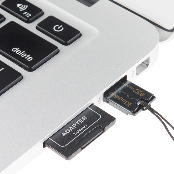 38 |
38 |  52 |
52 |  58 |
58 |  67 |
67 |  74 |
74 |  80 |
80 |  87 |
87 |  97 |
97 |  103 |
103 |  109 |
109 |  116 |
116 |  32 |
32 |  46 |
46 |  54 |
54 |  77 |
77 |  87 |
87 |  131 |
131 |  143 |
143 |  168 |
168 |  175 |
175 |  222 |
222 |  256 |
256 |  262 |
262 |  31 |
31 |  45 |
45 |  72 |
72 |  82 |
82 |  88 |
88 |  109 |
117 |
109 |
117 |  140 |
140 |  153 |
153 |  188 |
188 |  200 |
200 |  206 |
206 |  212 |
212 |  223 |
223 |  229 |
229 |  235 |
235 |  19 |
19 |  86 |
86 |  98 |
98 |  106 |
106 |  188 |
188 |  202 |
202 |  208 |
208 |  215 |
215 |  26 |
26 |  83 |
83 |  89 |
89 |  96 |
96 |  27 |
27 |  101 |
101 |
169 |  170 |
170 | |
172 |
| 175 | |
 5 |
5 |  12 |
12 |  19 |
19 |  12 |
12 |  23 |
23 |  4 |
5 | !!! attention
6 | This is not where customers should seek assistance on a product. If you require technical assistance or have questions about a product that is not working as expected, please head over to the [SparkFun Technical Assistance](https://www.sparkfun.com/technical_assistance) page for some initial troubleshooting.
7 |
4 |
5 | !!! attention
6 | This is not where customers should seek assistance on a product. If you require technical assistance or have questions about a product that is not working as expected, please head over to the [SparkFun Technical Assistance](https://www.sparkfun.com/technical_assistance) page for some initial troubleshooting.
7 |  18 |
18 |  25 |
25 |  36 |
36 |  43 |
43 |  62 |
62 |  69 |
69 |  76 |
76 |  83 |
83 | 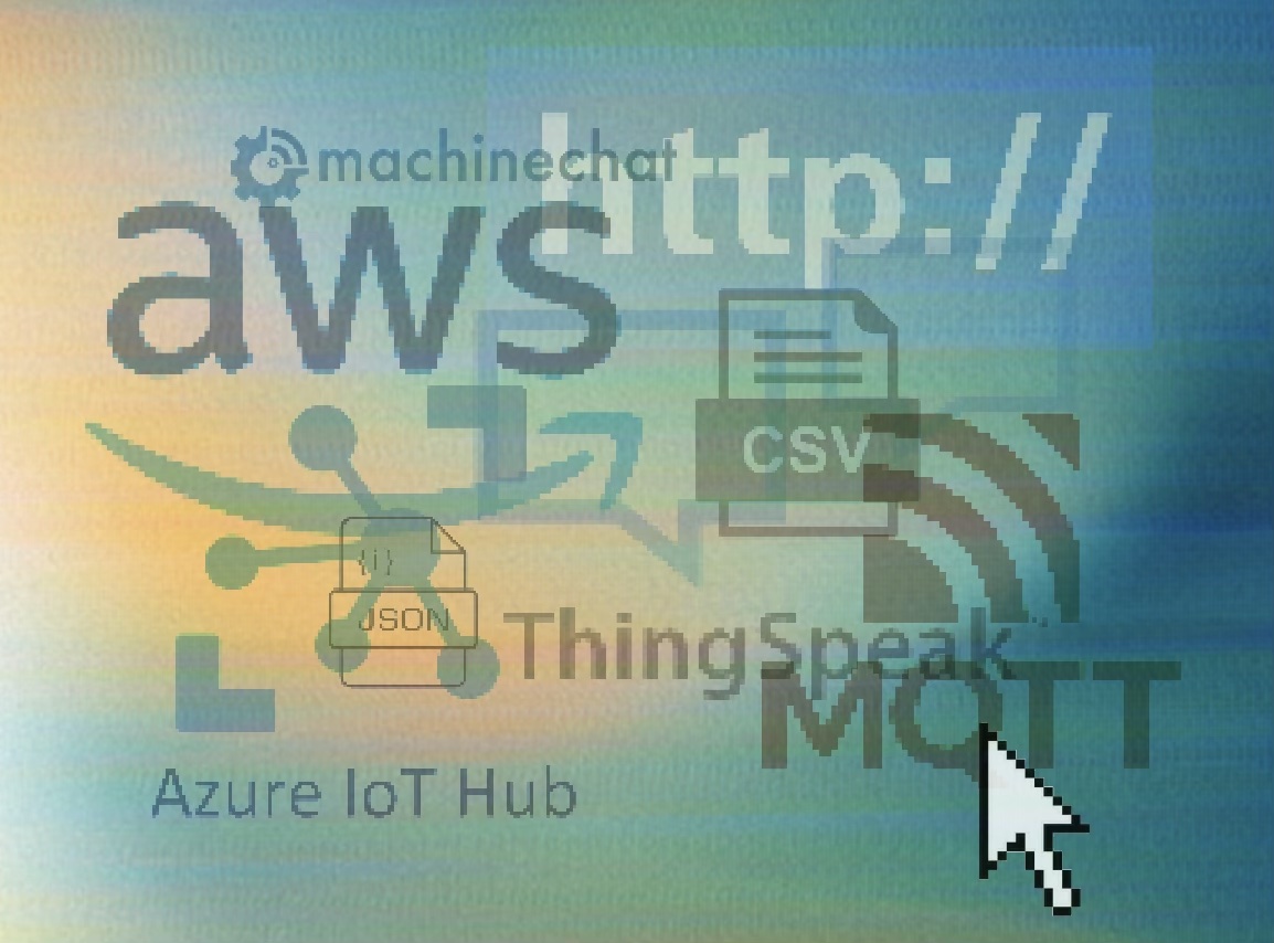 29 |
29 | 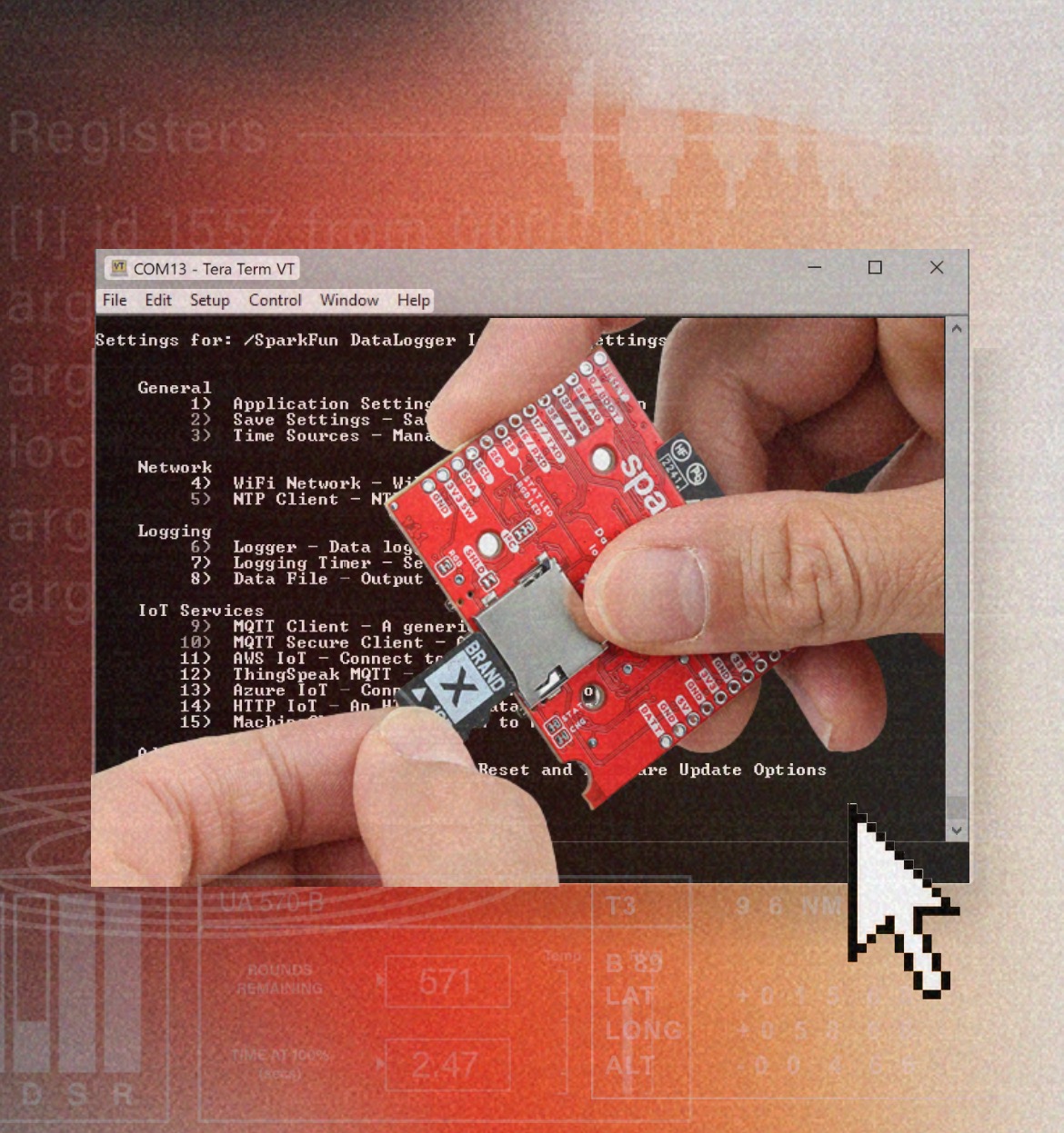 41 |
41 | 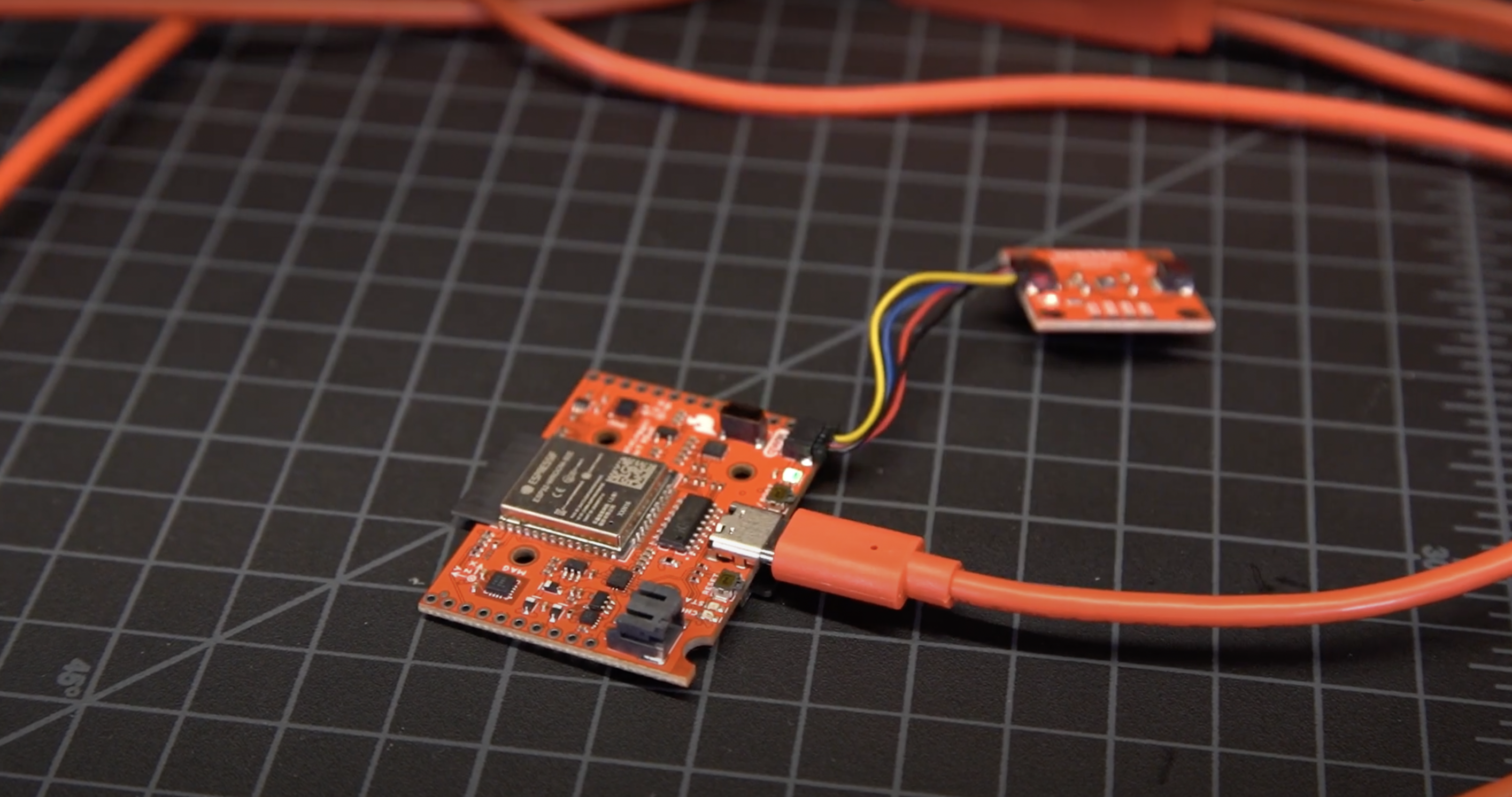 53 |
53 |  32 |
32 |  49 |
49 |  71 |
71 |  |
117 |  |
118 |
119 |
 127 |
127 |  137 |
137 |  152 |
152 |  28 |
28 |  |
36 |  |
37 |
 49 |
49 |  63 |
63 |  70 |
70 | |
87 |
 95 |
95 |  102 |
102 |  113 |
113 |  121 |
121 |  10 |
10 |  17 |
17 |  24 |
24 |  30 |
30 |  39 |
39 |